 Susanta K. Das
 Abhijit Sarkar2
 K. Joel Berry
- 1Department of Mechanical Engineering, Center for Fuel Cell Systems and Powertrain Integration Kettering University, Flint, MI, United States
- 2Michigan Molecular Institute, Midland, MI, United States
A hyper-branched polymer (HBP) electrolyte is synthesized for rechargeable lithium-air (Li-air) battery cell and experimentally evaluated its performance in actual battery cell environment. Several real-world battery cells were fabricated with synthesized HBP electrolyte, pure lithium metal as anode and an oxygen permeable air cathode to evaluate reproducibility of the rechargeable Li-air battery cell. The effect of various conditions such as various HBP based electrolytes, discharge current −0.1~0.5 mA, cathode preparation processes and carbon contents on the battery cell performance were experimentally evaluated using the fabricated battery cells under dry air condition. Detailed HBP electrolyte synthesis procedures and experimental performance evaluation of Li-air battery cell for various conditions are presented. The experimental results showed that different conditions and processes significantly affect the Li-air battery performance. Upon taking into account the effect of different conditions and processes, optimized HBP electrolyte materials, cathode process and conditions were determined. Several Li-air battery cells were fabricated with optimized conditions and optimized battery cell materials to determine the reproducibility and performance consistency. Experimental results showed that over 55–65 h of discharge occurred over 2.5 V terminal cell voltage with all three optimized Li-air battery cells. It implied that the optimized Li-air battery cells were reproducible and were able to hold charge over 2.5 V for more than 2 days. Experimental results of the Li-air battery cell with further refined optimized materials revealed that the battery cell can discharge more than 10 days (i.e., more than 250 h) at or above 2.0 V. The experimental results also showed that the Li-air battery discharge time got shorter as the discharge-charge cycle increases due to increase in internal resistances of battery cell materials. The experimental results confirmed that the lithium-air battery cell can be reproduced without loss of performance and can hold charge more than 10 days at or over 2.0 V. The investigation results obtained may usher a pathway to manufacture a long-life rechargeable Li-air battery cell in the near future.
Introduction
Recent introduction of sustainable electric vehicles (EV), plug-in hybrid electric vehicles (PHEV), or hybrid electric vehicles (HEV) in the transportation sector by replacing conventional combustion-engine vehicles were aimed at reduction of environment pollution caused due to emission of greenhouse gas by burning of fossil fuel (Reddy, 2002; Pistoia, 2005; Anderma, 2011; USCAR, 2018). For reliable operation of EV, PHEV, or HEV depends on stable power supply system (Scrosati et al., 2011; Tan et al., 2017). Currently EVs, PHEVs, and HEVs are loaded with the rechargeable lithium-ion battery pack for steady power supply and energy storage purpose (Reddy, 2002; Pistoia, 2005; Tan et al., 2017; USCAR, 2018). With continuous performance improvement for last few decades theoretical limits of energy density for lithium-ion batteries have reached almost to its peak (Reddy, 2002; Pistoia, 2005; Tan et al., 2017).
To replace lithium-ion battery pack with high density energy storage and power supply system, various electrochemical energy storage and power supply systems have been explored by numerous researchers (Whittingham, 2004; Zheng et al., 2008; Beattie et al., 2009; Girishkumar et al., 2010; Zhang et al., 2010; Chen et al., 2015). Among various high-power density energy sources explored so far the lithium-air battery commonly refer to as Li-O2 battery became one of the most promising candidate (Whittingham, 2004; Zhang et al., 2010; Chen et al., 2015). An oxygen permeable air cathode, an efficient electrolyte for ion conduction through it and a lithium metal anode are the three major components of a Li-air battery (Beattie et al., 2009; Zhang and Zhou, 2013; Chen et al., 2015; Das and Abhijit, 2016; Tan et al., 2017). The theoretical energy density of a conventional lithium-ion battery can be reached almost 10 times lower than that of a Li-air battery because of usage of pure lithium metal at the anode and pure oxygen at the cathode (Pistoia, 2005; Zhang and Zhou, 2013; Chen et al., 2015; Tan et al., 2017). Lithium is a very light weight metal and it has high theoretical specific energy of 13 kWh/kg among all other candidate metals as can be seen from Table 1. Oxygen at the cathode is fed from the atmospheric air free of cost and hence the Li-air battery will be very light weight and significant reduction in battery cost (Beattie et al., 2009; Wang et al., 2010; Li et al., 2013; Zhang and Zhou, 2013; Elia and Hassoun, 2015) can be achieved. The electrochemical reactions in the Li-air battery cell can be written as (Reddy, 2002; Zheng et al., 2008; Girishkumar et al., 2010):
The electro-chemical reaction mechanism, as shown in Equations (1)–(2), within the Li-air battery cell looks very simple but still there are numerous issues need to be resolved to improve Li-air battery performance such as (i) very low conductivity of the most conventional electrolytes against Li/O2 pair, (ii) high cell polarization causes low cell energy efficiency, (iii) impact of impurities and moisture on air-cathode materials, and (iv) very short battery cycle life (Li et al., 2013; Das et al., 2016; Asadi et al., 2018). Hence, a high conductive electrolyte and high-performance air cathode materials are required for an efficient operation of the lithium-air battery to improve the stability of Li/O2 discharge-charge reactions. To reduce or eliminate dendrite formation, flammability risks, thermal runaway, short-circuit formation and other safety concerns, use of the high-energy lithium metal, high proton conductive electrolyte, and efficient air cathode materials are required for safe lithium-air battery cell (Wang et al., 2010; McCloskey et al., 2011; Jung et al., 2012; Li et al., 2013; Zhang and Zhou, 2013; Elia and Hassoun, 2015; Das and Abhijit, 2016; Das et al., 2016; Wu et al., 2018; Zhanga et al., 2019) operation.
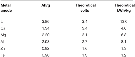
Table 1. Characteristics of metals used in metal-air batteries (Wang et al., 2010 and Li et al., 2013).
In this investigation, by combining high conductive polymeric materials onto a thermally and mechanically stable robust chemical structure, we synthesized a high performance hyper-branched polymer electrolyte following step by step procedures described in the subsequent sections below. In addition, a high-performance air cathode was also fabricated with an efficient oxygen permeable membrane to use in the rechargeable lithium-air battery cell. A real-world rechargeable lithium-air battery cell was fabricated using synthesized HBP electrolyte, a high-performance oxygen permeable air cathode and pure lithium metal at anode. Fabricated lithium-air battery cells were experimentally tested under various real-world battery operating conditions. Detailed description of synthesis procedures of different HBP electrolytes, air cathode materials preparation, and experimental results of the lithium-air battery performance are presented in the consecutive sections below.
Preparation of Hyper-Branched Polymer (HBP) Electrolyte
Step by step synthesis procedures to prepare initial HBP1–HBP5, and preparation of final hyper-branched polymer (HBP) electrolyte with HBP5 are described below.
Preparation of Si-H Terminated HBP1
Under N2, a flask was charged with tetrakis(dimethylsiloxy) silane (16.4 g, 50 mmol.), toluene (30 mL), tetra(ethylene glycol) diacrylate (10 g, 33 mmol.) containing some phenothiazine (0.15 g) and chloroplatinic acid [0.3 mL, 5 mg/mL in Tetrahydrofuran (THF)]. To make the mixture milky, the mixture was heated to 100°C and stirred for 12 h. The resulting milky mixture was cooled down to room temperature and diluted with 20 mL of isopropyl alcohol (IPA). The precipitate was then removed by centrifugation and filtration. The volatiles were removed from the filtrate by rotovap and Kugelrohr distillation at 120°C. The final product was obtained as a slightly viscous clear liquid. The synthesis reaction of HBP1 is shown in Figure 1.
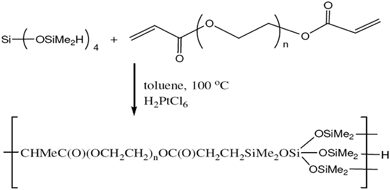
Figure 1. Synthesis of Si-H terminated HBP1.
Preparation of 100% Carbonate Terminated HBP2
First we prepared (allyloxy) methyl ethylene carbonate. For this, to a one-neck, 200 mL, round-bottomed flask fitted with a Dean-Stark trap and a condenser were added 3-allyloxy-1,2-propanediol (25 g, 189 mmol), dimethyl carbonate (55 g, 611 mmol), and K2CO3 (4 g, 28.9 mmol). The flask was heated to 95°C and the solution was stirred for 24 h while CH3OH was distilled out. The product was filtered and distilled. The distillate, having a boiling point of 125°C, was collected under 5 mm Hg reduced pressure.
A flask was charged under N2 with HBP1 (10 g), an excess of (allyloxy)methyl ethylene carbonate (10 g), and 1 drop of Karstedt catalyst. The resulting cloudy mixture became homogenous and clear in 5 min and was allowed to stir for another 5 h for reactions to settled down. The unreacted (allyloxy)methyl ethylene carbonate was removed by Kugelrohr distillation at 125°C.
Preparation of 75% Carbonate Terminated HBP3
Under N2, a flask was charged with HBP2 (10 g), (allyloxy)methyl ethylene carbonate (6.5 g, 46 mmol.), and 1 drop of Karstedt catalyst. The resulting cloudy mixture became homogenous and clear in 5 min and was allowed to stir for another 5 h. The FTIR spectrum (not shown here) revealed that the intensity of the Si-H peak relative to that of the C-H stretch decreased to 25% of that of HBP1.
Preparation of Si-H Terminated HBP4
Under N2, a flask was charged with HBP3 (10 g) and tetrakis (dimethylsiloxy)silane (20.5 g, 62 mmol.), poly(ethylene glycol) divinylether (10 g, 42 mmol.), and two drops of Karstedt catalyst in xylene. The mixture was stirred at room temperature for 30 min and then heated to 50°C and stirred for 12 h. The resulting slightly viscous clear liquid was cooled down to room temperature.
Preparation of Carbonate Terminated HBP5
Under N2, a flask was charged with HBP4 (10 g) and vinyl ethylene carbonate (2.5 mL, 26 mmol). The resulting mixture was allowed to stir at room temperature for 30 min and then heated to 50°C and stirred for 12 h. Then the carbonate terminated HBP5 is obtained in the flask.
Finalization of HBP Electrolyte
Propylene carbonate (PC) was dried over 4Å molecular sieves. Anhydrous ethylene carbonate (EC) was purchased from Aldrich and used as received. Lithium bistrifluoromethanesulfonimide (LiTFSI) was purchased from Aldrich and dried at 80°C under nitrogen for 2 days. Triethylene glycol dimethyl ether (TEGDME) and dimethoxyethane (DME) were distilled over sodium. Dimethoxy ethane (DME) was distilled from sodium hydride. Ionic liquid 1-butyl-1-methylpyrrolidinium bis-(trifluoromethylsulfonyl) imide (P14TFSI) was purchased from Aldrich and dried under vacuum at 90°C for 24 h. 1:1 EC/DME, 1.0 M LiTFSI solutions in 1:1 EC/PC (weight ratio), and TEGDME were prepared inside the glovebox using volumetric flasks. The final HBP electrolyte in LiTFSI solutions were prepared by addition of HBP5 (5 mL) to a LiTFSI (1.435 g, 5 mmol) THF solution followed by removal of the solvent under vacuum. Several different HBP-based electrolytes were finally prepared as described above including HBP with 1.0 M LiTFSI in PC, HBP with 1.0 M LiTFSI in 1:1 EC:PC, HBP with 1.0 M LiTFSI in 1:1 EC:DME, HBP with 1.0 M LiTFSI in TEGDME, HBP with 0.35 M LiTFSI in P14TFSI. The prepared HBP electrolyte with HBP5 in LiTFSI solutions were examined and conductivities of HBP electrolyte in different solutions were measured. The measured values of conductivities are presented in Table 2. From Table 2, it can be seen that HBP with 1.0 M LiTFSI in 1:1 EC:DME has the highest conductivity and HBP with 0.35 M LiTFSI in P14TFSI shows the lowest conductivity. The HBP electrolyte with different solutions having different conductivities were used to fabricate a real-world Li-air battery cell and the performance of the battery cell has been evaluated in this study.
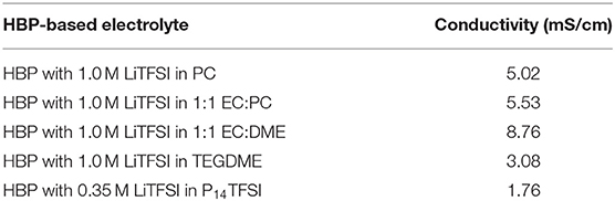
Table 2. Prepared HBP based electrolyte and measured conductivities.
Cathode Paste Preparation
Specific amounts of carbon and catalyst (if used) were mixed using a Kurabo Mazerustar planetary mixer as a general procedure. Then DI water (5–10 mL) was added into this mixture and the resulting slurry was shaken for 30 min, followed by the addition of the binder material (PTFE suspension) and then shaken for another 2 h. The resulting paste was transferred into a vial and was ready for cathode fabrication.
Air Cathode Fabrication Methods and Physical Properties
For fabrication of real-world lithium-air battery cell's air-cathode, 7/16 in diameter nickel foam discs were punched from a nickel foam plate and used for cathode fabrication. In this study, three different methods were evaluated to fabricate air-cathode as described below.
Applying and Pressing Method
In this procedure, the prepared cathode paste was applied and uniformly spread onto the nickel foam disc to cover the entire surface area. Then using stainless steel backing plates, the cathode paste coated disc was sandwiched between two sheets of PTFE coated aluminum foil. The entire unit was then pressed with 1000lb force in order to get good contact between the aluminum foil and coated disc. The air cathode thus prepared by applying and pressing was dried in air for 2 h and then in an oven at 115°C for 2 days. The dried air cathode was then transferred into the argon atmosphere glovebox to use in a battery cell.
Mixing and Sonication Method
Mixing and sonication method was used as an alternative process for the cathode fabrication which is described as follows. The cathode paste prepared earlier was diluted with a specific amount of DI water to form a suspension and two nickel foam discs were dropped into it followed by sonication for 3 h using a Branson 1200 sonicator. After sonication, the discs were taken out of the suspension and dried in ambient air and then in an oven at 115°C before they were brought into the glovebox for using it into the battery cell.
Ultra-Sonication Method
A third cathode preparation process was evaluated whereby ultra-sonication of the cathode paste (KJ:Co3O4:PTFE 80:10:10, 1 g) and DI water (4 mL) was used to uniformly mix the material. Ultra-sonication (Vibra Cell, Sonics and Materials, Inc.) was performed as a continuous process for about 1 h with the sample container placed in a water bath. At first the cathodes were prepared using the paste by the “applying and pressing” method and then use ultrasonication process. Hence this process can be referred to as “ultrasonication and pressing.”
Lithium-Air Battery Cell Fabrication Using Synthesized HBP Electrolyte
Lithium Anode and Separator Preparation
Lithium metal foil (Li-foil) was purchased from Aldrich. The surface of the lithium was scrubbed using a blade and smoothed between two pieces of weighing paper. After cleaning, 7/16 inch diameter lithium discs were punched and used as the anode. For separator, Whatman GF/F glass fiber filter paper was punched to ½ inch diameter discs and dried in an oven at 115°C for 2 days before transferring into the glovebox.
Battery Cell Hardware Preparation
A stainless-steel rod (½ inch diameter, 3 inch long) was fitted with a Swagelok PTFE ferrule and inserted into a ½ inch perfluoroalkoxy (PFA) union. Inside the union, a stainless-steel spring was placed between the rod and a stainless-steel spacer (½ inch diameter, 0.01 inch thickness). A stainless-steel tube (½ inch diameter, 3 inch long) was fitted with a PTFE ferrule and inserted into the other end of the union.
Lithium-Air Battery Cell Assembly
Several lithium-air battery cells were assembled in an argon atmosphere glovebox. The rod and spring were loaded into the union. The 7/16 inch diameter Li foil disc was placed on the spacer and compressed with a plastic spatula to encourage adhesion. With the spacer in contact with the spring and the Li foil facing out, the spacer and Li foil were loaded into the union. The HBP electrolyte loaded ½ inch diameter separator was placed on top of the Li foil. The carbon composite air cathode was placed on the top of the separator followed by the stainless-steel tubing. The joint was hand-tightened, and a rubber stopper was placed in the other end of the stainless-steel tubing before the cell was brought out of the glovebox.
Experimental Performance Evaluation of Li-air Battery Cell
The assembled lithium-air battery cells were experimentally tested for various conditions using.
ARBIN 2000BT battery testing machine/equipment which has simultaneous 12-channel battery cell/pack testing capability. Fisher Scientific Isotemp Oven was used for temperature/humidity control during battery cell testing and ARBIN's MITS Pro software installed computer was used for automatic experimental data acquisition purposes. Experimental data were plotted for various conditions and processes affecting battery cell performance as described in the results and discussions section below.
Results and Discussions
Characterization of HBP Electrolyte
The prepared HPB electrolyte is characterized through FTIR and TGA analysis in order to make sure the expected thermally stable hyper-branched polymer is formed within the HBP backbone. The FTIR spectrum of carbonate terminated HBP5 is shown in Figure 2. From Figure 2, we can see that hyper-branched polymer was formed during the reaction which can be clearly viewed through different peaks of the components of HBP electrolyte as wavenumber increases. The FTIR spectrum presented in Figure 2 revealed that the intensity of the Si-H end group peak relative to that of the C-H stretch decreased to form the final HBP5. Over time, the Si-H end groups may get hydrolyzed and become hydrophilic making the membrane more hydrophilic. It was observed that during reaction of the Si-H terminated HBP with vinyl terminated fluorocarbon, 80% of the Si-H end groups were converted to fluorocarbon end groups and the remaining Si-H end groups (20%) were converted to trimethoxysilane end groups for moisture crosslinking purposes of HBP5 as can be seen from Figure 2.
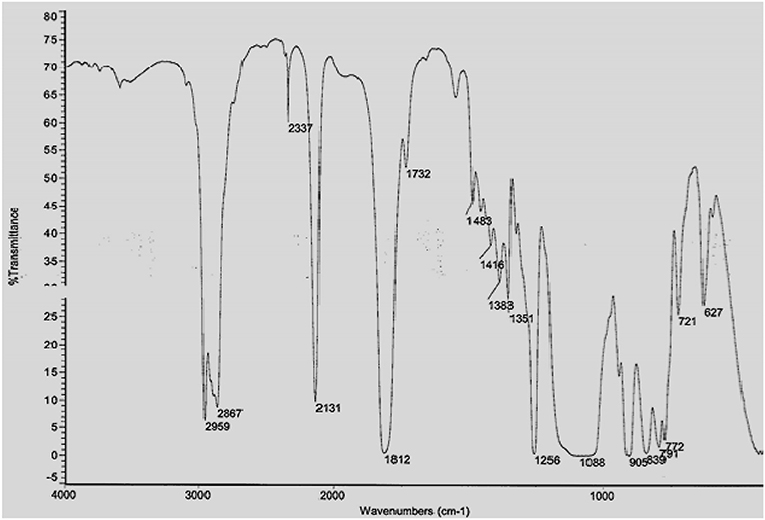
Figure 2. FTIR spectrum of carbonate terminated HBP5 (neat).
Figure 3 represents the TGA profile of hyper-branched polymer HBP5. TGA profiles represent the thermal behaviors and loss/gain characteristics of materials under thermally induced stress. From Figure 3, it can be seen that the hyper-branched polymer HBP5 has thermal stability up to 180°C with <5% weight loss of HBP5 electrolyte. It indicates that the prepared HBP electrolyte would be able to maintain good ionic conductivity and would also thermally stable at high temperature, up to 200°C. The conductivity of prepared different HBP electrolytes was measured in the argon atmosphere glovebox using a conductivity meter.
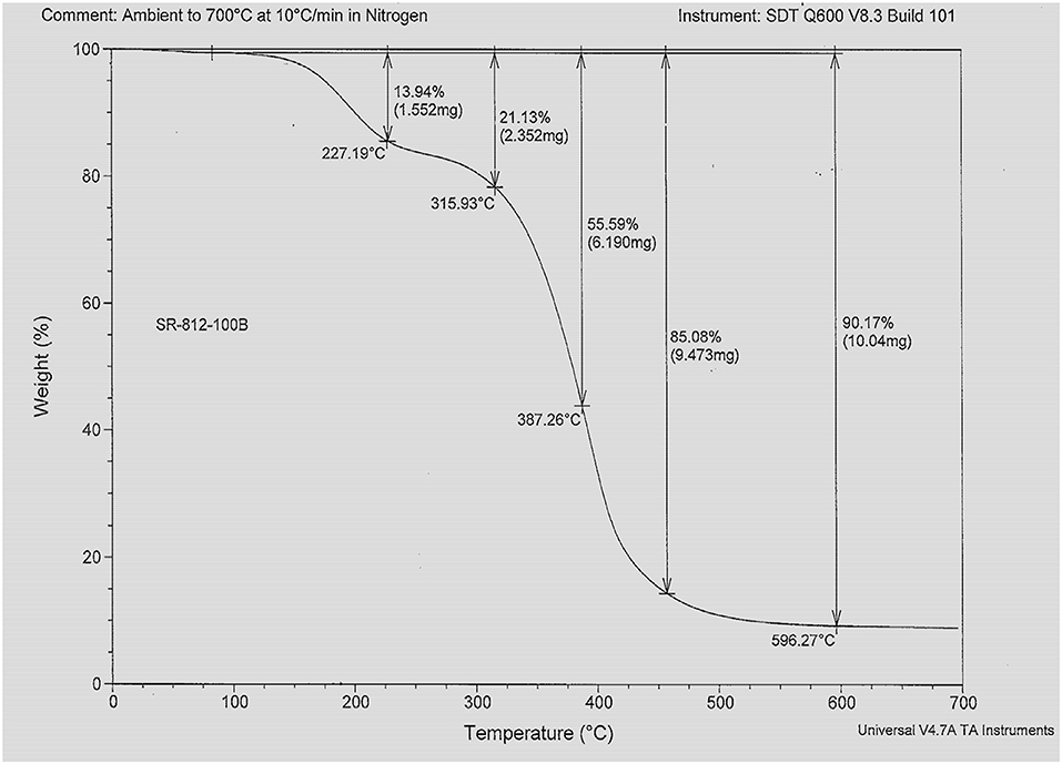
Figure 3. TGA profile of hyper-branched polymer HBP5.
Table 2 represents the measured conductivity of different electrolytes. From Table 2, it can be seen that the ionic liquid-based electrolyte is the least conductive due to its relatively high viscosity and low lithium salt solubility. The HBP with EC:DME solvents has the highest conductivity and HBP with PC has medium range conductivity. The measured conductivity of different electrolytes presented in Table 2 are much improved/comparable to the conductivities reported in Minakshi et al. (2011), Verma et al. (2014), and Takada (2018). After characterization of HBP electrolytes, Li-air battery cells were assembled in a glove box under an argon atmosphere and several Li-air battery cells were fabricated with the prepared cathodes, Li metal anode, and HBP electrolytes as documented in the Table 3. Fabricated cells were tested under various cell properties and cell operating conditions as discussed in the following sections.
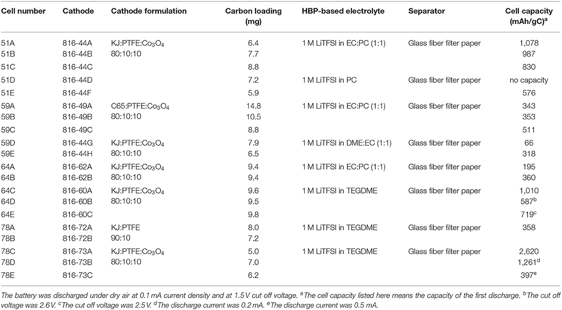
Table 3. Li-air battery cells fabricated utilizing the prepared cathodes and prepared HBP5-based electrolytes, and the measured cell capacity.
Effect of Carbon Source on Cell Capacity
The discharge products of Li-air batteries will precipitate on the surface of the carbon material since they are not soluble in organic electrolytes. It is known that the amount of discharge product the cathode can take up is directly related to the capacity of the battery cell. Therefore, the battery cell capacity is critically dependent on the surface area and pore volume of the carbon material. In this study, we investigated Ketjen black 600JD (KJ) and C65 as the carbon source and some of their properties are listed in Table 4. KJ is considered as a high surface area (1,400 m2/g) and high pore volume (2.47 cm3/g) carbon source while C65 is considered as a low surface area (62 m2/g) and low pore volume (0.32 cm3/g) carbon source as can be seen from Table 4. The pore size for both carbon sources are almost similar/comparable as can be seen from Table 4.
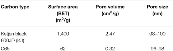
Table 4. Measured surface area and pore volume of KJ and C65 carbons.
Lithium-air battery cells using two different carbon-based cathodes were prepared and experimentally tested to learn the effect of carbon source on battery cell performance. Figure 4 represents discharge profiles of the battery cells with a KJ based cathode and with a C65 based cathode having the same level of carbon loading. From Figure 4, we can see that the C65 based battery cell shows simultaneous “U” type concave and convex shape of discharge curve instead of a flat one. The physical explanation for this type of discharge profile requires further investigation of C65 carbon characteristics especially resistances in contact with battery materials. On the other hand, KJ based battery cell displays flat line discharge profile as expected. It indicated that the KJ based cathodes may exhibit significantly larger capacity than that of C65 based cathodes.
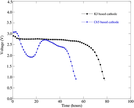
Figure 4. Discharge profiles of Li-air battery cell (Cell#51C in Table 3) at 0.1 mA (i.e., 50 mA/g) discharge current with a KJ based cathode and the Li-air battery cell (Cell#59C in Table 3) with a C65 based cathode having the same level of carbon loading.
Effect of the HBP Electrolytes on Battery Cell Performance
Several Li-air battery cells were fabricated with the same type of cathode but with different composition of HBP electrolytes in order to figure out the effect of HBP electrolytes on the battery cell performance. Figure 5 represents the fabricated Li-air battery cells discharge profiles for different HBP based electrolytes. From Figure 5 we can see that the cells with HBP with 1.0 M LiTFSI in PC as electrolyte showed very low or little capacity (blue line masked with solid square) and hence did not work well. In addition, the open circuit voltage (OCV) produced by the electrolyte, HBP with 1.0 M LiTFSI in PC, was very low - only 2.7 V. The characteristics of PC material may responsible for this poor performance by this type of HBP electrolyte. From Figure 5 we can see, however, that the battery cell with HBP with 1.0 M LiTFSI in 1:1 EC:PC electrolyte exhibited (black line masked with solid circle) flat discharge curves and much better performance. The battery cell with HBP with 1.0 M LiTFSI in 1:1 EC:DME (black line masked with solid rectangle) showed very low capacity, as can be seen from Figure 5, due to the volatile nature of DME since no membranes were used on this cell. From Figure 5, it can also be seen that the electrolyte, HBP with 1.0 M LiTFSI in TEGDME (redline masked with open diamond), exhibited much better performance among all the HBP based electrolytes. The performance of the battery cell with the ether-based electrolyte (black line masked with solid circle) was comparable to those of the carbonate based electrolyte (redline masked with open diamond) as can be seen from Figure 5.
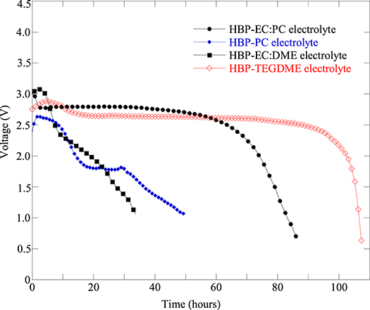
Figure 5. Discharge profiles of fabricated Li-air battery cells at 0.1 mA (equivalent to 50 mA/g) discharge current with different electrolytes: HBP with 1.0 M LiTFSI in 1:1 EC:PC (Cell#51B), HBP with 1.0 M LiTFSI in PC (Cell#51E), HBP with 1.0 M LiTFSI in 1:1 EC:DME (Cell#59E), and HBP with 1.0 M LiTFSI in TEGDME (Cell#64C). The cathode of these cells are all KJ based with same formulation.
Effect of Cathode Process on Battery Cell Capacity
In this investigation, three different cathode processes were tried in order to find the best one. Sonication and ultra-sonication were used to mix the material better and to enable the paste to better penetrate into the nickel foam pores. Figure 6 represents the discharge profiles of the battery cells with different cathode processes. It can be seen from Figure 6 that the battery cell fabricated with “mixing and sonication” (blue line masked with solid diamond) cathode process showed much lower discharge performance as well as lower capacity (see Table 3) than that of the battery cell performance with the cathode process by “applying and pressing” (black line masked with solid circle).
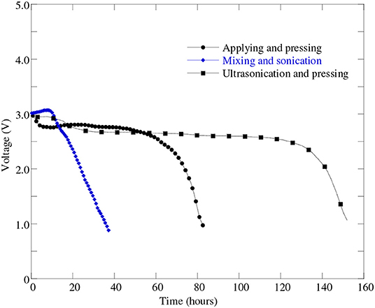
Figure 6. Discharge profiles of battery cells at 0.1 mA (i.e., 50 mA/g) discharge current with different cathode processes: “applying and pressing” (cell#51B), “mixing and sonication” (cell#64A), and “ultra-sonication and pressing” (cell#78C).
A possible reason for this poor performance for “mixing and sonication” process may due to a loose electrical contact between the carbon and metal since no pressing was applied. In order to improve the battery cell performance further we made another attempt to mix the paste better on the cathode using “ultrasonication” method. From Figure 6 it can be found that the battery cell with “ultrasonication” cathode process shown in black line masked with solid rectangle was able to discharge almost uniformly more than twice amount of time compared to other two cathode processes. It implies that the battery cell's discharge capacity improved greatly when used “ultrasonication” cathode process than the other two cathode processes—applying and pressing, and mixing and sonication. The battery cell discharge performance and capacity improvement occurred due to the fact that the ultra-sonication process helps the catalyst to disperse more uniformly on the surface of the battery cell's carbon material. The uniform distribution of catalyst helps electro-kinetics reaction of the battery cell occurred efficiently and hence increased battery cell's discharge performance.
Effect of Discharge Current on Cell Performance
The battery cell discharge current significantly affects the cell capacity. In order to assess the effect of discharge current on the cell performance and cell capacity we tested the fabricated Li-air battery cell with different discharge current amounts. Figure 7 represents the battery cell performance with different discharge current. From Figure 7, it can be seen that the cell performance is the best at discharge current 0.1 mA (i.e., 50 mA/g). Furthermore, as the discharge current increases from 0.1 to 0.2 mA and 0.5 mA the cell performance decreases significantly as can be seen from Figure 7. Moreover, it can be found from Table 3 that when the discharge current of 0.1 mA (cell#78C) was applied then the battery cell's discharge capacity was 2,620 mAh/gC. When increasing the battery cell's discharge current to 0.2 mA the battery cell's capacity was decreased to 1,261 mAh/gC (cell#78D). Further increasing the battery cell's discharge current to 0.5 mA caused the battery cell's capacity decreased to 397 mAh/gC (cell#78E). Results presented in Figure 7, Table 3 indicated that the Li-air battery cell will have better performance and capacity at low cell discharge current such as cell discharge at 0.1 mA (i.e., 50 mA/g).
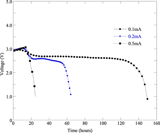
Figure 7. Discharge profiles of the same batch of Li-air battery cells under different discharge current levels: 0.1 mA (cell#78C), 0.2 mA (cell#78D), and 0.5 mA (cell#78E).
Optimization of Battery Cell Materials and Performance Evaluation
Upon taking into account the effect of cathode processes, electrolyte performance and type of carbon source on the Li-air battery cell performance, an optimized battery cell fabrication process was developed and three Li-air battery cells were fabricated using the optimized cathode material, carbon source, and HBP electrolyte inside the glovebox. The optimized battery cells performance were experimentally evaluated under real world operating conditions and reproducibility of the battery cell fabrication using the same electrolyte, anode, and cathode materials were verified. Figure 8 represents the experimental performance results of three.
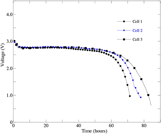
Figure 8. The first discharge profiles of three optimized battery cells those were prepared from the same batch of optimized cathode, HBP electrolyte, and anode materials at 0.1 mA discharge current.
optimized Li-air battery cells at 0.1 mA (i.e., 50 mA/g) discharge current. From Figure 8, it can be seen that all three optimized battery cells were able to discharge over 55 h i.e., charge stayed in the battery cell more than two days at over 2.5 V. The results presented in Figure 8 agrees well with the results reported in Wang et al. (2019). From Figure 8, the excellent reproducibility of the performance among the three optimized battery cells has been observed up to 55 h of battery operations. From Figure 8, it was also observed that the cell2 and cell3 were able to continue discharge up to 65 h at or above 2.5 V than the cell1. It indicated that the optimized battery cell fabrication process can be used to mass production of the Li-air battery for specific number of hours of battery operations before putting the battery cell into the charging dock.
The optimized cathode and anode materials were further refined following ultra sonication process discussed above and the HBP electrolyte was further rinsed with 1.0 M LiTFSI. The refined optimized Li-are battery materials were used to fabricate a Li-air battery cell using the battery hardware and following the battery cell assembly procedure discussed above. Figure 9 represents the experimental discharge-charge cycles results of the Li-air battery cell with refined optimized battery materials. From Figure 9 it can be seen that after refinement the Li-air battery cell was able to discharge for about 250 h i.e., more than 10 days in first discharge and the subsequent discharge time got shorter. The results presented in Figure 9 shows better Li-air battery cell performance than the results reported in Asadi et al. (2018) for different battery cycles. Comparing the results presented in Figures 8, 9, it can be found that the first discharge time is dramatically increased in the Li-air battery cell with refined optimized battery materials. The charging time of the Li-air battery cell is also got shorter as the battery discharge-charge cycle increases. It implies that the resistances in the Li-air battery cell materials may increases after first discharge and accumulated further inside the battery cell in the subsequent cycles as can be seen from Figure 9. Further investigation is needed to decipher the internal resistance characteristics of the Li-air battery materials during discharge-charge cycles in a future study.
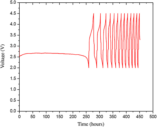
Figure 9. The discharge-charge cycles (13 cycles) with 0.1 mA current of the refined optimized Li-air battery cell that was prepared from the refined optimized cathode, HBP electrolyte, and anode materials.
Conclusions
Hyper-branched polymer based electrolyte has been synthesized, characterized, and experimentally evaluated its performance in a real-world Li-air battery cell with an oxygen permeable air cathode. Detailed synthesis procedures of hyper-branched polymer electrolyte, oxygen permeable air cathode preparation processes, and fabrication of real-world lithium-air battery cell were investigated. Real-world functioning lithium-air battery cells were fabricated using synthesized HBP electrolyte, air cathode, and lithium metal as an anode. The fabricated Li-air battery cells were experimentally tested under dry air and evaluated the effect of different conditions and processes. The battery cell was also evaluated experimentally to assess the effect of different discharge currents, 0.1–0.5 mA, on the battery cell's performance. The experimental results of the battery cells performance showed that the Li-air battery cell's discharge performance was significantly affected by different conditions and processes. By taking into account the effect of different conditions and processes, an optimized battery cell fabrication process was developed and fabricated three Li-air battery cells using the same optimized anode, cathode, and electrolyte materials to verify the Li-air battery cells reproducibility and performance. The experimental results revealed that all three optimized battery cells were capable to discharge more than 2 days at or over 2.5 V cell voltage at 0.1 mV discharge current i.e., Li-air battery cell's charge stayed more than 2 days at over 2.5V. In addition, it was also found that two of the battery cells (cell2 and cell3) among three optimized battery cells were able to continue discharge up to 65 h at or above 2.5 V. It meant that the excellent reproducibility of the Li-air battery cell performance can be obtained with the optimized battery cell materials. Experimental results of the Li-air battery cell with further refinement of the optimized battery cell materials showed that the battery cell can discharge more than 10 days at or above 2.0 V and as the discharge-charge cycle increases the Li-air battery discharge period got shorter due to increase in internal resistances of battery cell materials. It revealed that using the optimized battery cell fabrication process and materials, mass production of the Li-air battery can be achieved for specific number of hours of battery cell operations.
Data Availability Statement
All datasets used in this article were obtained through the investigation are available upon request.
Author Contributions
SD and AS conceived the idea and designed experiments. SD and AS jointly outlines the synthesis and characterize the battery materials, and conducted the experiments. SD analyzed the data, and wrote the manuscript. KB supported experimental data collection.
Funding
This work is accomplished under the funding support provided by the U.S. Department of Energy (DOE) – grant award number DE-EE0003109.
Conflict of Interest
The authors declare that the research was conducted in the absence of any commercial or financial relationships that could be construed as a potential conflict of interest.
References
Anderma, M. (2011). PHEV and EV Battery Technology Status and Vehicle and Battery. Market Outlook, AABC Europe. Available online at: https://www.totalbatteryconsulting.com/consulting/Selected-Publications.pdf (accessed May 2, 2019).
Asadi, M., Sayahpour, B., Abbasi, P., Ngo, A. T., Karis, K., Jokisaari, J. R., et al. (2018). A lithium–oxygen battery with a long cycle life in an air-like atmosphere. Nature 555, 502–506. doi: 10.1038/nature25984
Beattie, S. D., Manolescu, D. M., and Blair, S. L. (2009). High capacity lithium-air cathodes. J. Electrochem. Soc. 156, A44–A47. doi: 10.1149/1.3005989
Chen, L. Y., Guo, X. W., Han, J. H., Liu, P., Xu, X. D., Hirata, A., et al. (2015). Nanoporous metal/oxide hybrid materials for rechargeable lithium–oxygen batteries. J. Mater. Chem. A 3, 3620–3626. doi: 10.1039/C4TA05738D
Das, S. K., and Abhijit, S. (2016). “Synthesis and performance evaluation of a solid electrolyte and air cathode for a rechargeable lithium air battery,”in Proceedings. ASME 14th International Fuel Cell Science, Engineering and Technology Conference. (Charlotte, NC: Batteries and Energy Storage), 1-7. doi: 10.1115/FUELCELL2016-59448
Das, S. K., Jianfang, C., Salma, R., and Abhijit, S. (2016). Synthesis, characterization and performance evaluation of an advanced solid electrolyte and air cathode for rechargeable lithium-air batteries. J. Mater. Sci. Chem. Eng. 4, 74–89. doi: 10.4236/msce.2016.41012
Elia, G. A., and Hassoun, J. A. (2015). Polymer lithium-oxygen battery. J. Sci. Rep. 5, 12307–12314. doi: 10.1038/srep12307
Girishkumar, G., McCloskey, B., Luntz, A. C., Swanson, S., and Wilcke, W. (2010). Lithium-air battery: promise and challenges. J. Phys. Chem. Lett. 1, 2193–2203. doi: 10.1021/jz1005384
Jung, H. G., Hassoun, J., Park, J. B., Sun, Y. K., and Scrosati, B. (2012). An improved high-performance lithium–air battery. Nat. Chem. 40, 579–585. doi: 10.1038/nchem.1376
Li, F., Kitaura, H., and Zhou, H. (2013). The pursuit of rechargeable solid-state li–air batteries. J. Ener. Environ. Sci. 6, 2302–2311. doi: 10.1039/c3ee40702k
McCloskey, B. D., Bethune, D. S., Shelby, R. M., Girishkumar, G., and Luntz, A. C. (2011). Solvents' critical role in nonaqueous lithium–oxygen battery electrochemistry. J. Phys. Chem. Lett. 2, 1161–1166. doi: 10.1021/jz200352v
Minakshi, M., Pritam, S., Sharma, N., Blackford, M., and Ionescu, M. (2011). Lithium extraction-insertion from/into LiCoPo4 in aqueous batteries. Ind. Eng. Chem. Res. 50, 1899–1905. doi: 10.1021/ie102267x
Scrosati, B., Hassoun, J., and Sun, Y. K. (2011). Lithium ion batteries - a look into the future. J. Ener. Envir. Sci. 4, 3287–3295. doi: 10.1039/c1ee01388b
Takada, K. (2018). Progress in solid electrolytes toward realizing solid-state lithium batteries. J. Power Sour. 394, 74–85. doi: 10.1016/j.jpowsour.2018.05.003
Tan, P., Jiang, H. R., Zhu, X. B., An, L., Jung, C. Y., Wu, M. C., et al. (2017). Advances and challenges in lithium-air batteries. J. Appl. Energy. 204, 780–806. doi: 10.1016/j.apenergy.2017.07.054
USCAR (2018). United States Council for Automotive Research LLC. Available online at: http://www.uscar.org (accessed May 3, 2019).
Verma, M. L., Minakshi, M., and Singh, N. K. (2014). Synthesis and characterization of solid polymer electrolyte based on activated carbon for solid state capacitor. Electrochim. Acta. 137, 497–509. doi: 10.1016/j.electacta.2014.06.039
Wang, C., Xie, Z., and Zhou, Z. (2019). Lithium-air batteries: challenges coexist with opportunities. APL Mater. 7, 040701–040712. doi: 10.1063/1.5091444
Wang, D., Xiao, J., Xu, W., and Zhang, J. G. (2010). High capacity pouch type li-air batteries. J. Electrochem. Soc. 157, A760–A764. doi: 10.1149/1.3414828
Whittingham, M. S. (2004). lithium batteries and cathode materials. J. Chem. Rev. 104, 4271–4301. doi: 10.1021/cr020731c
Wu, B., Wang, S., Lochala, J., Desrochers, D., Liu, B., Zhang, W., et al. (2018). The role of the solid electrolyte interphase layer in preventing li dendrite growth in solid-state batteries. Ener. Environ. Sci. 11, 1803–1810. doi: 10.1039/C8EE00540K
Zhang, J. G., Wang, D., Xu, W., Xiao, J., and Williford, R. E. (2010). Ambient operation of li/air batteries. J. Power Sources. 195, 4332–4337. doi: 10.1016/j.jpowsour.2010.01.022
Zhang, T., and Zhou, H. (2013). A reversible long-life lithium–air battery in ambient air. Nat. Comm. 4:1817. doi: 10.1038/ncomms2855
Zhanga, R. H., Zhaoa, T. S., Jiang, H. R., Wu, M. C., and Zeng, L. (2019). V2O5-NiO composite nanowires: a novel and highly efficient carbon-free electrode for non-aqueous li-air batteries operated in ambient air. J. Power Sources. 400, 76–85. doi: 10.1016/j.jpowsour.2018.10.098
Keywords: hyper-branched polymer electrolyte, lithium-air battery cell, oxygen permeable air cathode, battery fabrication, experimental performance evaluation
Citation: Das SK, Sarkar A and Berry KJ (2020) Experimental Performance Evaluation of a Hyper-Branched Polymer Electrolyte for Rechargeable Li-Air Batteries. Front. Energy Res. 8:75. doi: 10.3389/fenrg.2020.00075
Received: 19 January 2020; Accepted: 14 April 2020;
Published: 20 May 2020.
Edited by:
Jiachang Zhao, Shanghai University of Engineering Sciences, ChinaReviewed by:
Jiulin Wang, Shanghai Jiao Tong University, ChinaManickam Minakshi, Murdoch University, Australia
Copyright © 2020 Das, Sarkar and Berry. This is an open-access article distributed under the terms of the Creative Commons Attribution License (CC BY). The use, distribution or reproduction in other forums is permitted, provided the original author(s) and the copyright owner(s) are credited and that the original publication in this journal is cited, in accordance with accepted academic practice. No use, distribution or reproduction is permitted which does not comply with these terms.
*Correspondence: Susanta K. Das, c2Rhc0BrZXR0ZXJpbmcuZWR1