Abstract
A software and control architecture for a humanoid robot is a complex and large project, which involves a team of developers/researchers to be coordinated and requires many hard design choices. If such project has to be done in a very limited time, i.e., less than 1 year, more constraints are added and concepts, such as modular design, code reusability, and API definition, need to be used as much as possible. In this work, we describe the software architecture developed for Walk-Man, a robot participant at the Darpa Robotics Challenge. The challenge required the robot to execute many different tasks, such as walking, driving a car, and manipulating objects. These tasks need to be solved by robotics specialists in their corresponding research field, such as humanoid walking, motion planning, or object manipulation. The proposed architecture was developed in 10 months, provided boilerplate code for most of the functionalities required to control a humanoid robot and allowed robotics researchers to produce their control modules for DRC tasks in a short time. Additional capabilities of the architecture include firmware and hardware management, mixing of different middlewares, unreliable network management, and operator control station GUI. All the source code related to the architecture and some control modules have been released as open source projects.
1 Introduction
In this paper, we describe the design decisions and the resulting software architecture of the Walk-Man robot, developed for the participation to the DARPA Robotics Challenge (DRC).
The goal of the DRC was to develop robots (not necessarily humanoid) capable to operate in a disaster scenario and to perform tasks, such as search and rescue, usually done by humans. During the challenge, the robot was required to perform different tasks, such as walk, drive a car, grasp and use objects, open doors, and rotate valves. The operator was located far from the robot, without line-of-sight, and not necessarily with a high bandwidth connection to the robot, so that direct teleoperation was not possible and a semi-autonomous approach was required. Thus, the operator was responsible for choosing the order and the timing of commands to solve the DRC tasks, depending on the level of autonomy of the robot. For example, the main task of opening a door might be handled by the operator with the following actions: reach the door handle, grasp it, turn and finally release it, or just with a single command: “open that door.”
The Walk-Man team was composed by engineers and technicians with different background and fields of expertise ranging from compliant manipulation, walking pattern generation, control, to artificial vision. Each contribution have been integrated in the software architecture thanks to the proposed design so that also non-experts in software engineering and code development were able to develop dedicated modules. This choice has avoided the necessity of training the whole team and, hence, reduced the time effort. In this paper, we use the terms “software users” and “control module developers” interchangeably to refer to the users of the software architecture we developed. Our design choices are motivated by the needs of such users, and they aim to maximize the output of any developer through a well-tailored software infrastructure, inter-process communication facilities, and shared libraries with various tools.
While some of our implementation decisions may not apply to large long-term projects, we followed many principles that are in common with the state of the art of robotic software development: specifically, we adopted a component-based approach that focuses on modularity to support code reuse and rapid development (Brugali and Shakhimardanov, 2010), for example, with similar requirements in the ROS ecosystem refer to Coleman et al. (2014) and Walck et al. (2014).
Following the standard approach of YARP (Metta et al., 2006) and ROS (Quigley et al., 2009) middlewares, we decided to build a distributed network of applications (nodes), so that each different process is independent and users can have more freedom when developing their own modules. To save development time and to focus on the specific tasks for the DRC, we relied as much as possible on software components available within existing frameworks. A first design choice has been the development of a Generic YARP Module (GYM) to provide a set of libraries for control purpose both to enhance code reuse and to have a common interface to manage the modules execution flow.
We decided to adopt the YARP middleware for the development of our software architecture, and in particular for the design of the software interface between the robot hardware and the nodes related to motor control. This choice was motivated by our direct expertise in the development of YARP and because YARP has proved to be quite reliable in experimental settings (Hammer and Bäuml, 2013). In addition, YARP provides functionalities for setting channel prioritization using QoS and different communication protocols. These features, at the time of writing, are not yet available with ROS (although the upcoming version of ROS will provide similar functionalities with the adoption of Data Distribution Service at the transport layer).
To get advantage of the large codebase available in the ROS ecosystem, we designed a mixed architecture that integrates ROS nodes. In the final architecture, ROS was used in the high-level operator GUI and for the 3D perception. The operator graphic interface is a fundamental component of the architecture, it allows the remote control of the robot by enriching the pilot awareness with the data coming from the robot. The single components of the GUI inherit basic functionalities from a Generic Widget, i.e., the graphical interface of a GYM.
Similar works have been developed by teams participating in the DRC Trials, such as Johnson et al. (2015) and Yi et al. (2015), and Hebert et al. (2015). Most of these works have a custom low-level communication library, or middleware, which ensures a real-time control loop and a high level inter-process communication system (such as ROS, Orocos, OpenRTM, and PODO). Given the requirements on the network bandwidth imposed by DARPA, a custom manager was used to connect the operator control station to the robot computer, usually using TCP and UDP protocols without any abstraction layer, with two middleware servers (e.g., RosCores) in the operator station and the robot. The same solution has been adopted by the Walk-Man team whose architecture is based both on ROS and YARP that did not properly handle unreliable channels at the time of the DRC. Indeed, centralized servers are limiting for unreliable networks, and a custom bridge communicating with different reliable networks (robot, pilot station, etc.) using a TCP/UDP protocol is required. To cope with such problems, a custom network bridge that handles both protocols with a custom, optimized serialization of messages has been developed.
The aim of this paper is to describe the software with particular attention on how the proposed architecture helped the Walk-Man team and, in turn, how the team feedback affected the architecture design. The main contributions of this paper are as follows:
a generic module template that captures a development pattern of robot control modules, avoiding the need to write the same boilerplate code multiple times in each module,
an hybrid communication middleware architecture that includes ROS and YARP, along with a custom bridge used to handle both unreliable networks and environments with multiple nameserver (i.e., roscore and yarpserver), and
the integration of the generic module template into the operator GUI, which is developed as a generic reconfigurable GUI capable of adapting to the DRC tasks as well as to future demos and lab projects.
The source code for the software described in this work can be found here: https://gitlab.robotology.eu/groups/walkman-drc
1.1 Robot Platform
The Walk-Man robot (see Figure 1) is a humanoid robot with 33 DoFs, each actuated by an electric series elastic actuator whose design is described in Negrello et al. (2015). Each motor is controlled by its own electronic board at a frequency of 1 kHz. These boards are connected to a shared ethercat network with 1 Gb bandwidth, used to send and receive joint position reference, along with other information such as temperatures, torques, and PID values. Five additional electronic boards in the ethercat network provide readings from the robot IMU and the four Force/Torque sensors, located in the wrists and ankles. A control pc with a quad-core i7-3612 runs the control software and is configured as the ethercat master.
Figure 1
Finally, a Multisense SL head, which contains a stereocamera and a LIDAR, is connected through its own 1 Gb network to a vision pc, with the same hardware components as the control pc. An external pilot pc is connected through a wireless network to the control pc and vision pc.
The operating system on all the computers is Ubuntu 14.04 modified with Xenomai, all the code is written in C++ except for the firmware, which uses a subset of C. See Figure 2 for an overview of the hardware and networks. It is worth mentioning that the whole robotic platform has been assembled for the first time 4 months prior of the DRC. As a consequence, all the motion control software tests on the hardware have been delayed until few weeks before the DRC. On the other hand, at the time of assembly, the proposed architecture was in an advanced stage of development and testing. Such asynchronous development of software control algorithms and the architecture has led to the necessity of a highly flexible and modular implementation of the latter.
Figure 2
1.2 Design Choices Overview
In this section, the strategies used to design the Walk-Man software architecture. A complete software stack has been built for the DRC consisting in a custom firmware, control modules tackling different tasks, a remote pilot graphical interface, and the whole architecture to manage and connect the different applications.
Due to the limited time constraint (around 10 months) and the variety of programing skills among our robotics researchers, our design choices were oriented to:
avoid code duplicates and enhance code reuse;
provide common shared C++ classes and utilities to the software users;
ease and speed up the production of significant code by hiding code complexity in simple APIs;
fast testing and debugging leveraging on simulators.
Following these principles, our core developers focused on low level interfaces, middleware management, and network and performance optimization.
We devised a layered component-based architecture, where each task of the DRC is handled by a single control module and modules interact with the hardware and each other through well-defined APIs. Once a rough and primitive API was defined, modules could be developed in parallel; in the meantime, shared functionalities could be improved under the hood of the high level control software without requiring code changes.
The YARP middleware has been chosen to obtain an abstraction layer for the hardware of the robot (sensors and motors) together with the set of interfaces. This abstraction layer allows to write code that can seamlessly interface to simulators or to the real robot (either remotely through the network or on the same machine using inter process communication). The initial phase of the development focused on the implementation of this abstraction layer for the simulated robot in Gazebo (Hoffman et al., 2014). This allowed to start performing experiments early on during the project. The same interface was implemented on the real robot allowing to transfer the code developed on the simulator with only minimal parameters changes.
2 Software Architecture
The Walk-Man architecture has been organized into four software layers (see Figure 3).
The top layer is the operator control unit, named pilotInterface.
A network bridge connects the pilot to the robot, where various control and perception modules form another layer.
An hardware abstraction layer remotizes the robot hardware and provides to the control modules a set of shared libraries (GYM) used to interact with the remote driver, called Ethercat Master.
The lowest layer is represented by the firmware running in embedded boards, each controlling one actuator.
Figure 3
2.1 Firmware-Ethercat
At the lowest level, each joint of Walk-Man is controlled by a PID position loop in a distributed embedded electronic system with one board per joint. Our main aim was to have a hard real-time loop in the firmware: the execution time of each firmware function was measured and tuned so that a 1 kHz loop could be implemented. In the software architecture, we developed for the Coman platform, the communication from the control pc to each board was performed on an ethernet BUS using a combination of UDP and TCP packets. The lack of synchronization between boards led to conflicts and consequent packets loss with UDP and delays with TCP protocols. We decided to move to an ethercat implementation, which allows synchronized communication and, therefore, much better control on the data traveling on the BUS. In particular, we measured the maximum number of bytes that each board could handle at 1 kHz and defined a standard packet size with standard information, as shown in Figure 4.
Figure 4
This standard packet definition is an example of the various interfaces between software levels that will be described in this work and that allow software decoupling and testing.
2.2 Ethercat Master – YARP
In the real robot, the hardware manager runs on the control pc and is called Ethercat Master. It manages Ethercat slaves (i.e., the electronic boards), keeps them synchronized, and sends/receives position references in real-time.
The Master can be seen as a hardware robot driver, which handles low level communication and exposes a simpler and asynchronous API to the higher levels. Writing real-time code requires expertise that were not available in all the software developers. Therefore, a separation between the Master and the modules implementing higher-level behaviors has been introduced. This separation was achieved through the YARP middleware using the remotization functionalities that it provides for the robot abstraction layer. Usually, developers write software that communicates with the Master through the network; this has been achieved using asynchronous communication with the YARP middleware. This decoupling was beneficial because it allows stopping and starting modules without interfering with the Master. More importantly, it prevents modules that behave erratically to affect the real-time performance of the Master.
The Master creates an input and output YARP port for each control module and for each type of information required by them. In Figure 5, the modules running during the DRC driving task are reported together with communication frequencies.
Figure 5
2.3 Hardware/Simulation Abstraction Layer
The Ethercat-Master exposes the robot sensors and actuators in a YARP network by remotizing the robot with a set of YARP communication channels (this is achieved in YARP using special objects called network wrappers). An additional set of libraries, named WholeBodyInterface, hides YARP channels from control modules, and relieves the developers from the bureaucracy required to prepare and parse the messages to and from the robot. The composition of the YARP wrapper in the Ethercat-Master and the whole-body libraries realizes a two-tier Habstraction Layer (HAL) for the robot. This abstraction layer between the hardware driver and the control modules allowed us to easily switch between simulation and the real robot, since the Gazebo plug-ins for the Walk-Man robot implements exactly the same YARP classes and interfaces as the Master (see Figure 6).
Figure 6
In the simulation case, the Gazebo Plugin substitutes the HAL standalone application and it is fully compatible with the same set of shared libraries.
The two-tier abstraction layer implements a whole-body interface on top of the robot interface defined by YARP. The main difference between the two layers is that the latter separates joints in kinematic chains and implements interfaces for individual sensors; for practical reasons, the logical separation of the kinematic chains at this level is subject to fluctuations (for example, it affects how joint states are broadcast on the network). The whole-body interface groups all joints and associated sensors in a single kinematic chain. The advantage of this separation is that it exposes to the user the whole-body interface, which is stable because it is defined solely by the number of joints of the robot.
As an extreme example, 15 days before the DRC, we had to intentionally break the functions responsible for moving the robot joints. To reduce resource usage (and reduce jitter due to CPU overload), we changed how joints are grouped and transmitted on the network; all the required changes affected the YARP abstraction layer and remain limited to the implementation of the whole-body interface. All the user code remained untouched. The simulation, the real robot, and all the control modules were updated in just 2 days.
As suggested by Johnson et al. (2015), we fully understand (and wish) that in a long-term project APIs must not be modified, especially few days before the demo. However, we are convinced that, in a research environment APIs may need to be changed in critical moments, and the proposed approach is a way to mitigate the effect of such changes.
Finally, an advantage of this two-layer architecture is that it separates control modules from the middleware. This will allow to change the communication layer (i.e., the middleware) without affecting the control code.
2.4 Generic Control Module Template
A control module software can be summarized as a sense-compute-move loop, where sense receives all the inputs from the robot, the inputs are used by compute in order to implement the control law of the module. Finally, move sends to the robot the newly computed desired position of the joints. In reality, developers usually spend a part of development effort into initialization code: i.e., reading control parameters, starting the communication facilities, reading a description of the robot kinematics, and so on. We provided explicit support for this implementation pattern in the Generic YARP Module (GYM). The GYM has been designed as a C++ abstract class that provides a common and standard way to execute these initialization steps, along with a sense and move default implementation that provide boilerplate code required to initialize the YARP remotization interfaces. The source code of GYM can be found here: https://github.com/robotology-playground/GYM
GYM functions handle all the required YARP communication between a module, the Master, and the PilotInterface, effectively hiding YARP communication mechanisms and classes. GYM was iteratively improved driven by the effort to remove duplicated code across modules and based on the team feedback (10 developers) which helped revising the specifications and debugging.
Our experience showed that the adoption of GYM reduced duplicated code significantly. In addition GYM provides another separation between the code and the middleware. In fact, a Generic ROS Module is currently in development and complies with the GYM API, so that any module using GYM could also be used in the ROS system.
GYM is organized in two threads: a watchdog running at 1 Hz and a main control loop running in a range of frequencies between 100 and 500 Hz (Figure 7). Developers can write their own code inside the control loop function run(), they also have access to a set of helper function providing a standard kinematic description of the robot based on the robot URDF. The watchdog thread is not customizable and listens for standard commands from the pilot, through one of the standard communication interfaces (switch interface) described in the next section.
Figure 7
The GYM C++ class that needs to be inherited by the user has the following signature:
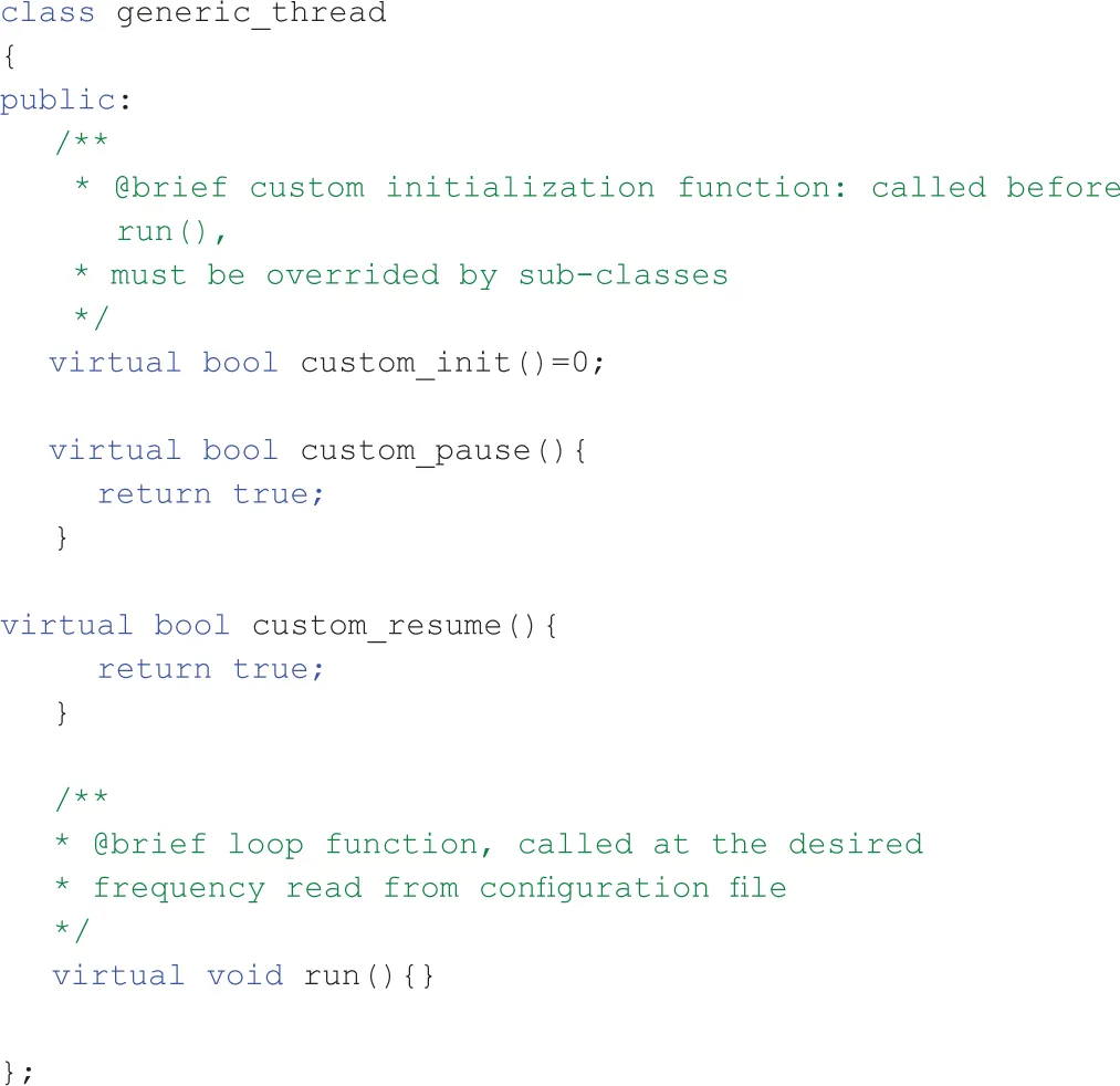
Notice that the user can override the default (empty) implementation of pause and resume functions so that he can take the required actions in order to save and resume the state of his own control module. Instead, to keep different modules organized in a similar structure, the init function was required to be implemented by the user and to contain all the initialization code. Moreover, with this approach, executables could be started in any moment, while the pilot kept the possibility of choosing when a module was going to be initialized and connected to the rest of the running software.
In order to show some of the GYM library functions, we report a simple run implementation:
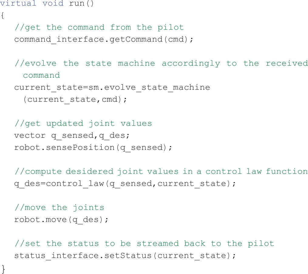
The variable robot is provided by GYM and is used to interact with the hardware with simple functions such as sensePosition and move.1
Examples of what a complex implementation may do is to use multiple state machines depending on the cmd values, to read or ignore commands from the user, to selectively avoid sensing or moving the robot while planning a complex movement, or even to evolve a state machine automatically without requiring user commands.2
2.4.1 Communication Interfaces
One of the features implemented in GYM code is a set of communication interfaces between the module and the pilot: Command, Status, Warning, and Switch. These interfaces in their default implementation send through the network an array of characters; the Command and Status interfaces support the addition of a custom data serializer that can be implemented by the user in order to send any type of data.
The Command Interface is used to send commands to the robot related to the precise task being executed, such as “go_straight 10” to make the robot walk for 10 meters or “set_valve 0.5 0 0.1 0 0 0 1 Waist” to set the valve data for the turning valve task with respect to the Waist robot reference frame.
The Status Interface is used to send back to the pilot any information the developer considers necessary to understand the internal state of the control module, such as “turning valve,” “walking,” “ready.”
The Warning Interface is an advanced interface that can be used in dangerous situations (e.g., when the balancing is compromised) to raise warning states in which the robot can assume a particular behavior (e.g., blocking every movement), from which specific actions can be performed to restore a safe state. The main differences between this interface and the Status are the priority of the data in the communication between control pc and pilot pc, and the different visualization in the pilotInterface, where Warning messages are red (see Section 2.7).
The Switch Interface is used to send the following commands to each module: start, pause, resume, stop, and quit. Since some of these commands are critical, they cannot be overridden with different implementations: modules are allowed to re-implement only pause and resume functions. This approach guarantees that any bug or misbehavior of the code running inside a GYM does not propagate to the whole system, since a module can always be forced to stop by the pilot with a stop command. Note that, differently from pause, the stop command does not activate any soft exiting procedure. For example, trying to stop the walking module while the robot is dynamically walking may result in a fall: if the pilot wants to stop the robot from walking and avoid falling, he should send the pause command to the current walking module, which in turn, depending on the robot status, should either stop immediately (double stance phase) or finish the current step phase and put both feet on the ground. Manipulation modules are safer in this sense since the robot is usually stable when moving its arms, nevertheless, a pause procedure should still be implemented as it allows the module to save its internal state and resume it later. Thus, the stop is used to quit a module when it is no longer needed, or to force-quit a module that is not controlling the robot but could be stuck in a loop due to bugs.
2.4.2 State Machine
The behavior of the GYM state machine is reported in Figure 8. Except for the special states Constructor and Destructor, there are three available states. The unique state accessible from the Constructor is Running through the start command. From this state, the module can be put into Paused state using the pause command or stopped (i.e., put into Stopped state using the command stop). From the Paused state, the module can be switched to the Running one by the resume command or can be stopped. Once the module is in the Stopped state, it can be only started (i.e., put into Running state through the command start). The Destructor state is accessible from every state sending the quit command. Changes of state are triggered by the watchdog thread in response to a message from the Switch Interface.
Figure 8
In the Running state, the internal control module loop is executed, the robot can receive the commands and send the state. The Paused state is used to freeze the internal control module loop so that, once resumed, the last command is executed. In the Stopped state, the internal control module loop is exited, as the program is closed, but it can be restarted again using the Switch Interface. To develop this state machine, we have been inspired by the OROCOS (Bruyninckx, 2001) Component Lifecycle StateMachine.
A generic representation of a control module using the GYM template together with the related widget is depicted in Figure 9.
Figure 9
2.5 Control Modules
Thanks to the GYM classes and functions, our team managed to focus on the core development of each DRC task in very short time (e.g., the module used to drive was developed in 10 working days by one single developer). It is worth noting that, although the perception module is not a proper control module, since it does not send references to the robot joints, it has been developed using the GYM template. This module uses ROS drivers to acquire data from the Multisense SL head and the standard command/status/switch interfaces to interact with the pilot. We will now describe the main components of a GYM Module, using the module designed for the driving task as an example.
The underlying structure of every control module is composed by:
an Inverse Kinematics solver;
a Finite State Machine (FSM); and
a trajectory generation library,
and resembles the structure of a hybrid control architecture with discrete states associated with continuous control laws. For example, the state machine for the driving module is shown in Figure 10. The principle of the module is the following: a message arrives through the command interface and depending on the message information, a different transition event is triggered, which may result in a change of state. After a new state transition, a new trajectory is created for one or more end-effectors. During the control loop, a portion of the trajectory is sent to the Inverse Kinematics solver, which computes the correspondent portion of joint displacement to be sent to the robot. Modules related to manipulation tasks uses a WholeBody Inverse Kinematics library by Rocchi et al. (2015), while the module related to walking uses a different strategy and Inverse Kinematics inspired by Kryczka et al. (2015). Indeed, we decide to give freedom to the control module developers, so that they could use the control laws and IK approaches that they were more familiar with. Two control modules, based on the proposed architecture, are described in detail in Ajoudani et al. (2014) (for the valve task) and Lee et al. (2014) (for the door task).
Figure 10
2.5.1 Finite State Machine
In order to cope with complex tasks, a Finite State Machine is used to switch between different actions of the robot. Once the operator receives the new status from the status interface, he can send a message through the command interface to change the module state accordingly to the structure of the FSM. As an example, referring to the driving task and the FSM reported in Figure 10, once the pilot receives the information that the status “reach” has been achieved, he can send the “approach” command. Many transitions are not possible because they would result in an incoherent behavior of the robot, such as moving a hand away from the wheel while still grasping it. Every state corresponds to a specific action or to a waiting state.
2.5.2 Trajectory Generator Library
The trajectory generator library consists of a set of trajectories of two types: linear and circular. The linear trajectories are created via fifth-order polynomials, interpolating from the initial and final positions. On the other hand, the circular trajectories are parameterized on the angle of rotation: the polynomial interpolates from the initial to the final angular displacement of the trajectory. The library provides a C++ class that can be initialized with the desired type of trajectory. The API methods allow to set the trajectory parameters, get an arbitrary point of the trajectory, and reset the generator to start a new trajectory.
2.6 Unreliable Channel Management
Our robot is used with two common types of network configuration between the pilot pc and the robot. The first setup is similar to a lab environment, where the network is fully operational and the bandwidth is at least 100 Mb/s. The second one is inspired by a realistic disaster scenario, where a wireless network is discontinuously working and the average bandwidth is less than 1 Mb/s. It is desirable to have most of the software architecture independent from the network capabilities, in particular the code running in control modules and in the pilot interface should not require any changes depending on the network. Both YARP and ROS use centralized servers for naming look-up (respectively called yarpserver and roscore).
When working in the first configuration, we used a single yarpserver and roscore so that modules can communicate directly with each other; there are no networking issues from pilot to robot.
In the real-world scenario, a direct communication may result in frequent disconnections and the centralized YARP/ROS servers may not be able to recover from such disconnections. Thus, a strong division between pilot pc and the robot has been proposed, with two pairs of roscore/yarpserver running, respectively, on the pilot pc and the control pc, splitting modules into a robot subsystem and a pilot subsystem. The two subsystems are bridged using a network manager that transparently interconnects modules between the two. The developed network manager behaves as a two-way bridge between the pilot pc and the robot, it is completely transparent to the processes it connects, meaning that there is no way for the processes to understand if they are communicating through a bridge or directly. Our bridge is developed as a pair of processes, running on two different computers, called BridgeSink (in the sender pc) and BridgeSource (in the receiver pc). The Boost Asio library (Kohlhoff, 2003) was used to abstract UNIX sockets and obtain an asynchronous behavior in the communications.
For the sake of clarity, we introduce an example of the bridge transparency capabilities. Consider two PCs (PC1 and PC2) with one module each (Module Alice and Module Bob, respectively). In the first scenario, Module Alice on PC1 is sending info to Module Bob on PC2 using YARP through a direct connection (i.e., disabled bridge), Alice will try to connect to Bob and will find a YARP port PB in the remote PC2, while Bob will listen from Alice’s remote YARP port PA in PC1.
In a second scenario the bridge is enabled, and it reproduces the port PB in PC1 and the port PA in PC2 so that Alice will actually connect to a local (in PC1) YARP port faking PB that is provided by the BridgeSink process running on PC1. On the other hand, Bob will listen from a local(PC2) YARP port faking PA provided by the BridgeSource running on PC2. Finally, BridgeSink and BridgeSource will internally transfer information from PC1 to PC2.
For network management purposes, the proposed bridge uses heuristics whose most important options are the bridge channel protocol (UPD or TCP) and the middleware (YARP or ROS). It is worth noting that the only unsupported combination is a TCP-ROS bridge, since ROS data would saturate the channel.
In Figure 11, we report the location (motor PC, vision PC, pilot PC) where the various programs are executed, focusing on the TCP/UDP bridge role.
Figure 11
2.6.1 TCP Bridge
Recall that YARP is used for all the communications between pilot pc and control pc, i.e., starting and stopping modules, modules status, modules commands. Those data are relatively small (see Table 1) and have high priority; thus, they are usually transmitted through a TCP channel. The bridge is heavily optimized to reduce the data overhead, such as TCP or YARP headers. It uses a configuration file to know which module should be redirected through the bridge, and associates with each module port an 8-bit identifier that is used as a header. An example of the configuration file is shown below:
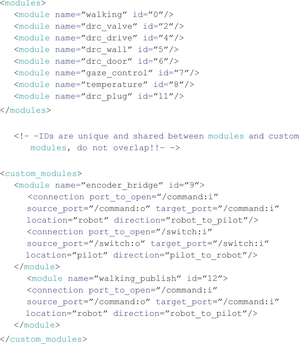
Table 1
| From robot | Number | Dimension (bit) | Total (bit/s) | Info |
|---|---|---|---|---|
| Joint IDs | 33 | 8 | 264 | Robot state |
| Joint encoders | 33 | 16 | 528 | Robot state |
| Joint toques | 33 | 8 | 264 | Robot state |
| Board temperatures | 7 | 16 | 112 | Seven joints per second |
| Module statuses | 5 | 16 | 80 | Dictionary-based compression |
| Overhead fixed | 1 | 512 | 512 | Serialization overhead |
| Overhead variable | 10 | 64 | 640 | Serialization overhead |
| Total | – | – | 2400 |
Bandwidth usage from the robot to the Pilot, not including TCP overhead, assuming T = 1.
Note that standard GYM modules are handled automatically, while custom modules require some more information. Indeed, they offer more configurability and allow for port renaming.
All the communications requested during T seconds are packed in a single TCP packet using the 8-bit identifier to keep the original header information. In the case where a port produces multiple packets, they are all dropped except the last one. This effectively reduces the frequency of streaming port, while maintains intact pilot commands.
T is chosen depending on the network bandwidth and delay, in the DRC it was set to 0.5 s. This leaves almost 50% of the channel free to be used, e.g., to send commands from the PilotInterface to the robot modules or to start a ssh shell in the control pc.
2.6.2 UDP Bridge
ROS perception-related data and other streaming information from the robot require low latency. For this type of information, it makes little sense to implement a reliable transport that requires retransmission when packets are loss. Lost data become obsolete and it is much better to read new messages than require re-transmission. For this reason, it is preferable to use UDP protocol.
Since PointClouds and RGB Images are usually larger than the UDP packet size, they need to be split and reconstructed. This is usually done automatically by the UDP protocol implementation, but if a single packet is lost, the whole data are dropped.
Our bridge avoids this problem by splitting point clouds and images into smaller ones, each representing a 3D or 2D sub-region of the original data, so that each one is a standalone pointcloud/image contained into a UDP packet (1500 bytes). By using timestamps, the original data are reconstructed in the pilot pc. This choice results in a delay in the visualization, since BridgeSource waits to receive as many data pieces as possible in an amount of time δt. In the DRC, the parameter δt was set to 0.4 s, which ensured receiving more than 90% of the original point cloud with a delay that was visible by the pilot but not critical since there was no teleoperation involved.
All the module statuses, the robot temperatures, and encoder readings (YARP based) are also sent in the UDP channel at a different (higher) frequency than the TCP one.
2.7 Pilot Interface
To remotely control Walk-Man, a GUI, called Pilot Interface (PI), has been developed. We followed a modular approach, using Qt libraries and ROS libRViz for 3D rendering (Kam et al., 2015). Every DRC task has a dedicated widget and can be used standalone. Moreover, we also developed widgets that allow interaction with the 3D representation of the environment and widgets for monitoring the robot state.
Using our approach, the operator could monitor the environment and the robot status and could make correct decisions to perform the tasks. Figure 12 shows a screenshot of the PI during the driving task.
Figure 12
Following the approach adopted for the GYM, we developed the Generic Widget (GW) so that every control module widget has the same basic features. In particular, the GW has already the capability to send messages to the Switch Interface and receive information from the Status Interface (see Figure 13).
Figure 13
For the sake of clarity, the driving task widget is reported in Figure 14. On the top of the widget, there is the Switch/Status Interface-related buttons, the rest is divided into three parts. On the left, we put the buttons to set the steering wheel position and place the hand on it, together with the buttons to adjust the position of the foot dedicated to the throttle. In the center, there are the buttons to rotate the steering wheel, while sliders are used to help the pilot understanding the current steering wheel position. Finally, on the right, we placed the button for the throttle. In this case, the operator can specify the duration and the amount of throttle.
Figure 14
In contrast to the other DRC teams, we managed the interaction between the robot and the pilot from the motion planning perspective. In fact, our pilots did not explicitly ask and check for a motion plan before the execution started. Instead, the pilots completely relied on the correct on-board open-loop Cartesian generation and kinematic inversion, and checked only the resulting robot position at the end of the execution. This approach was a viable choice thanks to the structural compliance of the robot joints, which handles small unexpected forces from outside, such as the effect of pushing a door with the arm. Moreover, with its soft and adaptable design, the robot hand can grasp an object with a large position/orientation error, it can even hit a surface with its finger without breaking them, and finally it can keep its grasping capabilities even with some broken fingers. With these premises, it is clear that a collision with the environment or a wrong placement of the end-effector with respect to the object do not affect the result of the task. If the robot hand misses the grasp or hits a surface, the operator will simply move the arm back and try again. The use of the Warning Interface to inform the operator of external forces or robot instability further improved our strategy.
An early work describing the initial design of the Pilot Interface is in Settimi et al. (2014). In the months between this preliminary work and the DRC, many features such as the Generic Widget have been added. The pilot was given the possibility to activate advanced modes, where commands, usually hidden, are shown and all the buttons are enabled (the pilot knew that this mode was risky, but it might be needed to override safety behavior in an unexpected situation).
Based on the forgiveness design principle an implementation of the Qt:QPushButton named QtTimedButton has been provided: after the click, a countdown of 3 s is displayed on the button before sending the command; the command can be stopped by re-clicking on it (this is used for dangerous commands to undo erroneous or undesired clicks).
To improve the pilot awareness of the robot state, we introduced a tab dedicated to the status, showing temperatures of the boards, torques of the motors, and battery level (see Figure 15) together with the modules statuses and warning messages. A logging utility for commands sent to the robot and statues received has been added, the visual data from the robot is logged as well in order to be able to completely reproduce and analyze the events.
Figure 15
Configuration files give the user the possibility to customize the displayed widgets. In the Darpa Robotic Challenge, three pilots with three different PCs were in the pilot station, each one being focused on different critical aspects: execution of the tasks, perception of the environment, and robot status.
3 Results: The DRC Experience
The first important test of the proposed architecture has been the DRC. Later, other 4 official occasions have occurred between September and November 2015 during which both the hardware and software Walk-Man platforms have been tested. Regarding the DRC, the team got 2 out of 8 points in the competition (consisting in 2 runs) for the accomplishment of the drive and door tasks. Team strategy was to get a penalty in time and avoid the egress of the vehicle task. The dimension of the DRC door has obliged the pilot to enter the indoor scenario walking sideways. The cameras on the Walk-Man head could not provide an accurate vision feedback to compute footstep poses and the irregularity of the terrain made the robot falling after the door was crossed in one of the two runs. During another run issues with the battery and the electronic power management forced the team to accept another time penalty to reset the robot and unfortunately the time left for the run was over.
3.1 Software Components Analysis
The components running on the robot were a set of control modules, the network bridge, a point cloud grabber, multiple webcam grabbers, and the hardware abstraction layer, with ROS and YARP nameservers. In particular, the control modules were paused and resumed when needed, in order to avoid multiple modules controlling the same joints at the same time. On the other hand, on the pilot computers, multiple pilot interfaces and the network bridge were running, along with ROS and YARP nameservers. The data flows inside the robot computers were very simple: all the control modules were connected to the bridge (and consequently to the pilot) and to the hardware abstraction layer. The perception modules were only sending data to the pilot, while the hardware abstraction layer was connected to the ethercat network and received data from the control modules. Finally, all the pilot GUIs were connected to the bridge (and consequently to the control modules on the robot) and to each other.
During the drive task, the driving control module was activated along with the previous listed modules. After the reset, the driving module was stopped, while the walking module was enabled; and the latter was paused and resumed multiple times during the door task in order to allow the door control module to open the door. Indeed, as mentioned, the ethercat master is able to receive inputs from different modules at the same time, and since walking and door modules operate on the same joints, they could not be run together, although they were both needed to execute the task.
The gaze control module was instead active all the time, this way the perception pilot could watch around and place virtual markers in the 3D visualization window. The window was seen and used by all the pilots on their respective computers thanks to the distributed structure of the pilot interface.
The software components used for networking were the first to be tested during the rehersal of the DRC, and performed in a stable and deterministic way. The setup of the bridge was straightforward; during the simulated DRC outdoor mode, the pilot interface received all the information published by the robot, each data at its own designed frequency. Instead, during the simulated indoor mode the TCP channel kept providing critical data, and UDP started to provide pieces of point clouds and images at random times, as expected.
In the competition, we did not have the chance to test the indoor mode, but in the outdoor part, the pilots faced multiple resets, including complete power-offs of the on-board computer. Once restarted, the bridge automatically re-established all the YARP and ROS connections, showing the power of its transparent behavior.
During the days before the competition, multiple pilot GUI configurations were used to test the robot components.
For example, the developers of the walking control modules used a single computer with a GUI configuration having few status widgets and only one control widget (the walking one) to tune their controller parameters, while the driving test required two pilots, one controlling the gaze and the other using the driving module to steer the wheel and accelerate.
Finally, the pilot checking the robot and network status could add another computer and another GUI during the tests whenever he needed to.
In the 5 days of tests inside the DRC garage, we experienced a single crash of one GUI, probably due to a graphic driver error. After the crash, it was sufficient to start again the GUI with the same configuration and both ROS and YARP middleware allowed to reconnect the GUI and the robot with no issues.
The GUI design helped pilots avoiding errors and parallelizing tasks. The QtTimedButton safety feature, which was never needed during trainings, has been exploited for the first and only time during the DRC. During a locomotion phase, the robot was positioning itself sideways with respect to the door; the pilot sent a command to the Walk-Man robot to rotate on the spot. The locomotion expert in the pilot room suddenly figured out that rotating on the spot in that particular inclined terrain could lead to a fall, if an extra stabilization procedure was not used, and he alerted the main pilot. Since the button related to the rotate on the spot command is a QtTimedButton, and the 3-s safety time window was not expired, the pilot was able to re-click the button and stop the sending of the command. This prevented the robot from falling in that situation.
The start/stop feature of GYM and the capability of modules to initialize in any robot configuration was used by the pilots a couple of times when they were no longer sure about the module status, e.g., after an unexpected network problem that disconnected the TCP safe channel (an issue of the DRC network).
As we already pointed out, the use of multiple pilots and a distributed interconnected architecture between their computers represented a remarkable choice. The advantages were demonstrated during various moments of the challenge, especially in the cooperation between the main pilot and the perception one. Indeed, the main pilot delegated to the perception pilot, among other duties, the superimposition of 3D objects to the scene in the manipulation tasks (e.g., grabbing the steering wheel or the door handle) and the continuous checking of the robot surroundings to decide how to avoid collisions and what to do during the driving. Thus, the main pilot could just focus on the correct execution of the various control sub-tasks required by each DRC task, reducing the amount of stress and consequently the error probability.
3.2 Beyond DRC
As mentioned, the Walk-Man platform has been used in several occasions after the DRC verifying its simple usage and longevity. A first example of a lab experiment is the development of a visual servoing manipulation task to improve robot autonomy. This work uses both a perception ROS module and a manipulation GYM module, which was successfully developed in few days thanks to the code and tasks already available.
During Eurathlon 2015 and IROS15, the Walk-Man robot performed various exhibitions. The executed tasks were walking, door opening, and valve turning. The walking and door task performed as during the DRC, in a stable and repeatable fashion. It was the first time that the valve task was publicly shown outside the lab and outdoor. The task performed very well and multiple times, demonstrating its reliability and robustness to positioning errors.
The last exhibition of the robot has been in Rome for the Maker Faire Rome 2015: in this occasion the robot had to break a band to inaugurate the event and then greet the audience. We were enough confident in the behavior of the hardware abstraction layer that a colleague located in another city developed the band breaking task in the Gazebo simulator and then sent the code to the Istituto Italiano di Tecnologia labs in order to have it tested on the hardware. The code worked on the real robot out of the box.
Another relevant aspect of this demo has been the use of a single pilot. This was required due to limited space on the stage and the necessity of a quick setup. By using a reconfigured lighter pilot interface, the pilot, who was the one responsible for the status of the robot during the DRC, was able to manage every aspect, from the communication to the successful execution of the task.
4 Discussion
The Walk-Man architecture has proven to be functional and robust in several different occasions and environments (indoor/outdoor challenges, labs experiments for research). Even during the architecture development, no particular criticality has been encountered to make us deviate from the original design. Three main factors have contributed to the chosen architecture design: limited time for implementation, heterogeneity of expertise of code users, and no prior availability of the hardware and, hence, lack of tested control laws.
Solutions adopted to cope with those factors, and discussed in this paper, have worked properly in any occasion the platform has been used. Even though not all the choices were a priori optimal, they have proven to work properly in our particular case. We will now discuss the outcomes of some of those choices starting from those made to overcome the strict time deadlines.
The most striking example of the effort done in avoiding the boilerplate code, together with the use of GYM, is the DRC driving module. Indeed, it was developed in a very small amount of time by a master student (i.e., non-expert code developer), which managed to control the gas pedal and to steer the wheel in less than 2 weeks. The module was then refined and tested for a week by two developers of the team and eventually used in the challenge.
It is well known that the design of a modular architecture does not always come for free, requiring significant time effort. Indeed, each software layer requires its own API to interface with others, and dedicated maintenance and update. Nevertheless, our team could have never been able to develop and change the modules without such APIs: the few main issues (e.g., multi-threading issues, network bridge incompatibility with custom YARP ports) encountered during the few months before the competition have been solved in a small amount of time without compromising or delaying the work of other software users.
An unintuitive and apparently wrong practice, in case of complex hardware and software platforms, such as Walk-Man, is the arbitrary choice in critical components implementations as we did for the network bridge. Indeed, non-architecture developers were not informed at all of the inner structure of the bridge. Although this in principle may lead to errors or integration issues, the alternative approach of discussing the design of the bridge among all the team members was prohibitive and required too much time. After the bridge implementation, each of the few issues emerged was solved jointly with the involved people.
Usually, in large companies and in organized open-source projects, coding quality standards, style, and procedures are mandatory and adopted by the whole team. Such approach requires dedicated advanced training and hence time. In our case, the team was formed on purpose for the DRC by including researchers of different groups with different expertise and standards. In similar situations, we strongly suggest to let every programmer choose his programing style and control approaches designing a flexible architecture to support the different users. Our architecture reflects this need by not enforcing any specific control algorithm in the modules implementation, so that developers were free to read just the sensors and to control the joints they required to achieve their specific tasks. As an example, control approaches could range from open-loop joint-space trajectories to inverse dynamics using a combination of force-torque, joint torques, and IMU measurements.
Another solution to cope with short time, which should not be underestimated, is the human pilot capabilities and improvements thanks to training. In particular, there was a trade-off between the effort required from the pilots during the challenge and the software development effort required to offload them from some tasks. As an example, we decided to skip the development of an artificial vision system for automatic object detection and recognition, and trained the perception pilot in order to be very fast and accurate in those tasks. We also noticed that, in the short time, accustom the pilot to each module’s behavior pays off as much as an improvement in the module code or control law. Note that this solution cannot be used successfully in every situation. For example, in case on untrained pilots or in high complex tasks (e.g., teleoperated balancing), the only possible approach is the use of a dedicated control software.
For example, our architecture requires tens of modules to be running at the same time across multiple computers, and the modules starting order may become complex to maintain. After the first tests with the whole architecture running, we noticed that lot of pilot effort had to be put in starting the modules in the right order. We decided to reduce such requirements as much as possible, and finally ended up with only the ROS and YARP nameservers to be started before all the other modules. We believe that the effort to provide asynchronous starting order is compensated whenever the architecture complexity increases up to the point where the pilots can no longer manage the order.
While the whole architecture has demonstrated to work properly, some useful utilities were not integrated and left to each developer preferences. In particular, multiple different logging utilities in each module were storing information useful for debugging purposes both on the robot and on the pilot PCs. Some pieces of the stored information were sent commands, status of the robot, point clouds, failures, and warnings from the control modules. Although these logging utilities were custom designed and simple in their capabilities, they provided enough information to speed up the unavoidable debugging process. Their helpfulness prompted us to include, in future architecture updates, a generic logging class integrated in each module with the same style of GYM and GW.
To conclude, the architecture structure and implementation did not affect any task during the DRC, and did not impose any constraint on the control strategies implemented in each task module. Few main issues (e.g., multi-threading issues, network bridge incompatibility with custom YARP ports) were detected during the months before the competition, and they were solved in a small amount of time without affecting or compromising the software developers work. Indeed, the future progressive improvements planned by all the team members mostly relate to the perception modules providing artificial vision and object tracking, a walking module capable of reflex-style reactions to terrain irregularities and an increased automatic error handling in manipulation modules in order to provide single-click complete task execution improving robot autonomy. On the other hand, the architecture general structure is widely accepted by team members and will require very few changes. The main features to be added are hard real-time support and a Matlab-EthercatMaster interface.
Statements
Author contributions
MF, LM, AS, AR, EMH, AC, DK, CP, and LN worked on the design of the global architecture and on the network. LM, MF, AR, EMH, AC, and NT designed and developed GYM and the HAL. AS and CP developed the operator control station GUI and many control modules. LP and NT coordinated and advised other authors on all the aspects of this work.
Acknowledgments
This work is supported by the European commission project Walk-Man EU FP7-ICT no. 611832. The authors would like to thank Stefano Cordasco and Alessio Margan for their work on the design and implementation of electronic boards and firmware.
Conflict of interest
The authors declare that the research was conducted in the absence of any commercial or financial relationships that could be construed as a potential conflict of interest.
Footnotes
1.^For the complete list of the helper functions, see https://github.com/robotology-playground/idynutils/blob/whole_robot_wrapper/src/RobotUtils.cpp
2.^For some GYM real modules, please see https://gitlab.robotology.eu/walkman-drc/drc_drive/blob/master/src/drc_drive_thread.cpp or https://gitlab.robotology.eu/walkman-drc/gaze_control/blob/whole_robot/src/gaze_control_thread.cpp
References
1
AjoudaniA.LeeJ.RocchiA.FerratiM.HoffmanE. M.SettimiA.et al (2014). “A manipulation framework for compliant humanoid coman: application to a valve turning task,” in Humanoid Robots (Humanoids), 2014 14th IEEE-RAS International Conference on (Madrid: IEEE), 664–670.
2
BrugaliD.ShakhimardanovA. (2010). Component-based robotic engineering (part II): systems and models. IEEE Robot. Autom. Mag.17, 100–112.10.1109/MRA.2010.935798
3
BruyninckxH. (2001). “Open robot control software: the orocos project,” in Robotics and Automation, 2001. Proceedings 2001 ICRA. IEEE International Conference on, Vol. 3 (Seoul: IEEE), 2523–2528.
4
ColemanDT.SucanIA.ChittaS.CorrellN. (2014). Reducing the barrier to entry of complex robotic software: a moveit! case study. J. Software Eng. Robot.5, 3–16.
5
HammerT.BäumlB. (2013). “The highly performant and realtime deterministic communication layer of the aRDx software framework,” in 16th International Conference on Advanced Robotics, ICAR 2013 (Montevideo).
6
HebertP.BajracharyaM.MaJ.HudsonN.AydemirA.ReidJ.et al (2015). Mobile manipulation and mobility as manipulation design and algorithms of RoboSimian. J. Field Robot.32, 255–274.10.1002/rob.21566
7
HoffmanE. M.TraversaroS.RocchiA.FerratiM.SettimiA.RomanoF.et al (2014). “Yarp based plugins for gazebo simulator,” in Modelling and Simulation for Autonomous Systems: First International Workshop, MESAS 2014, Vol. 8906 (Rome: Springer), 333.
8
JohnsonM.ShrewsburyB.BertrandS.WuT.DuranD.FloydM.et al (2015). Team IHMC’s lessons learned from the DARPA robotics challenge trials. J. Field Robot.32, 192–208.10.1002/rob.21571
9
KamH. R.LeeS.-H.ParkT.KimC.-H. (2015). Rviz: a toolkit for real domain data visualization. Telecommun. Syst.60, 337–345.10.1007/s11235-015-0034-5
10
KohlhoffC. (2003). Boost. Asio. Available at: http://www.boost.org/doc/libs/1
11
KryczkaP.KormushevP.TsagarakisN.CaldwellD. G. (2015). “Online regeneration of bipedal walking gait optimizing footstep placement and timing,” in Proc. IEEE/RSJ Intl Conf. on Intelligent Robots and Systems (IROS 2015) (Hamburg).
12
LeeJ.AjoudaniA.HoffmanE. M.RocchiA.SettimiA.FerratiM.et al (2014). “Upper-body impedance control with variable stiffness for a door opening task,” in Humanoid Robots (Humanoids), 2014 14th IEEE-RAS International Conference on (Madrid: IEEE), 713–719.
13
MettaG.FitzpatrickP.NataleL. (2006). Yarp: yet another robot platform. Int. J. Adv. Robot. Syst.3, 43–48.
14
NegrelloF.GarabiniM.CatalanoM. G.MalzahnJ.CaldwellD. G.BicchiA.et al (2015). “A modular compliant actuator for emerging high performance and fall-resilient humanoids,” in 2015 IEEE-RAS 15th International Conference on Humanoid Robots (Seoul: IEEE), 414–420.
15
QuigleyM.ConleyK.GerkeyB.FaustJ.FooteT.LeibsJ.et al (2009). “Ros: an open-source robot operating system,” in ICRA Workshop on Open Source Software, Vol. 3 (Kobe: IEEE-RAS).
16
RocchiA.HoffmanE. M.CaldwellD. G.TsagarakisN. G. (2015). “Opensot: a whole-body control library for the compliant humanoid robot coman,” in Robotics and Automation (ICRA), 2015 IEEE International Conference on (Seattle: IEEE), 6248–6253.
17
SettimiA.PavanC.VarricchioV.FerratiM.HoffmanE. M.RocchiA.et al (2014). “A modular approach for remote operation of humanoid robots in search and rescue scenarios,” in Modelling and Simulation for Autonomous Systems: First International Workshop, MESAS 2014, Vol. 8906 (Rome: Springer), 192.
18
WalckG.CupcicU.DuranT. O.PerdereauV. (2014). A case study of ROS software re-usability for dexterous in-hand manipulation. J. Software Eng. Robot.5, 36–47.
19
YiS.-J.McGillS. G.VadakedathuL.HeQ.HaI.HanJ.et al (2015). Team THOR’s entry in the DARPA robotics challenge trials 2013. J. Field Robot.32, 315–335.10.1002/rob.21555
Summary
Keywords
software architecture, humanoid robot, modular design, DRC challenge, teleoperation, robotic middlewares, emergency response
Citation
Ferrati M, Settimi A, Muratore L, Cardellino A, Rocchi A, Mingo Hoffman E, Pavan C, Kanoulas D, Tsagarakis NG, Natale L and Pallottino L (2016) The Walk-Man Robot Software Architecture. Front. Robot. AI 3:25. doi: 10.3389/frobt.2016.00025
Received
26 November 2015
Accepted
12 April 2016
Published
10 May 2016
Volume
3 - 2016
Edited by
Giuseppe Carbone, University of Cassino and South Latium, Italy
Reviewed by
Paolo Boscariol, University of Udine, Italy; Matthias Rolf, Oxford Brookes University, Japan
Updates
Copyright
© 2016 Ferrati, Settimi, Muratore, Cardellino, Rocchi, Mingo Hoffman, Pavan, Kanoulas, Tsagarakis, Natale and Pallottino.
This is an open-access article distributed under the terms of the Creative Commons Attribution License (CC BY). The use, distribution or reproduction in other forums is permitted, provided the original author(s) or licensor are credited and that the original publication in this journal is cited, in accordance with accepted academic practice. No use, distribution or reproduction is permitted which does not comply with these terms.
*Correspondence: Mirko Ferrati, mirko.ferrati@gmail.com
Specialty section: This article was submitted to Humanoid Robotics, a section of the journal Frontiers in Robotics and AI
Disclaimer
All claims expressed in this article are solely those of the authors and do not necessarily represent those of their affiliated organizations, or those of the publisher, the editors and the reviewers. Any product that may be evaluated in this article or claim that may be made by its manufacturer is not guaranteed or endorsed by the publisher.