 Jun-Young Lee
 Brian Byunghyun Kang
 Dae-Young Lee
 Sang-Min Baek
 Woong-Bae Kim
 Woo-Young Choi
 Jeong-Ryul Song
 Hyeong-Joon Joo
 Daegeun Park
 Kyu-Jin Cho*
- Biorobotics Laboratory, Department of Mechanical and Aerospace Engineering/SNU-IAMD, Seoul National University, Seoul, South Korea
This paper introduces SNUMAX, the grand winner of the RoboSoft Grand Challenge. SNUMAX was built to complete all the tasks of the challenge. Completing these tasks required robotic compliant components that could adapt to variable situations and environments and generate enough stiffness to maintain performance. SNUMAX has three key components: transformable origami wheels, a polymer-based variable stiffness manipulator, and an adaptive caging gripper. This paper describes the design of these components, and how they worked together to allow the robot to perform the contest’s navigation and manipulation tasks.
Introduction
Soft robotics involves using compliant actuation and control strategies and soft materials to create robots with soft robotic features (Albu-Schaffer et al., 2008; Rus and Tolley, 2015; Mazzolai and Mattoli, 2016). This new paradigm for building robots yields novel designs and functionalities (Trimmer, 2014). For example, the structure of a robot with a soft body can be deformed so it can safely and adaptively interact with the environment. Researchers from a wide variety of fields are focusing on developing design methodologies and manufacturing processes for this new type of robot (Kim et al., 2013a). The inaugural RoboSoft Grand Challenge of spring 2016 offered a venue for researchers to test the performance of new soft robots against a range of international teams (RoboSoft CA, 2016).
The challenge consisted of two test scenarios: terrestrial navigation and object manipulation. The terrestrial navigation tests mimicked the environmental conditions of an urban disaster area and tested robots’ ability to cope with rough terrain and navigate obstacles in order to help humans. The manipulation scenario involved three tests of robotic dexterity in handling objects in a range of situations.
Our team developed a robot, SNUMAX, which completed all the tasks in the terrestrial navigation and manipulation scenarios (Figure 1). SNUMAX has three key components: an origami transformable wheel, a polymer-based variable stiffness manipulator (PVSM), and an adaptive caging gripper. The transformable wheels allow the robot to navigate unstructured terrain and pass through narrow gaps and are stiff enough to sustain the robot’s weight. The manipulator is flexible enough to be maneuvered around obstacles and can be stiffened to allow it to pick up an 1-kg object with its gripper. The gripper has an under-actuated tendon routing system with a soft structure that allows it to adaptively grasp objects of various shapes. The gripper’s weight is minimized by including only one actuator.
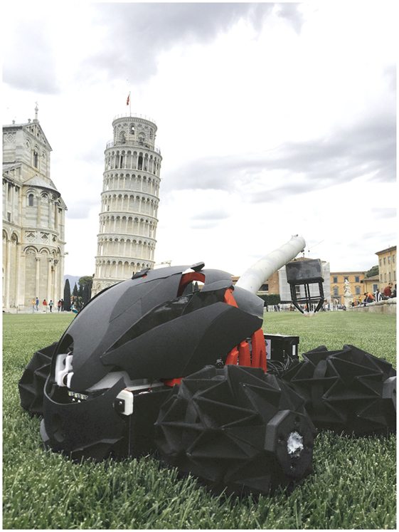
Figure 1. SNUMAX completed all tasks of the RoboSoft Grand Challenge, thanks to its transformable origami wheels, polymer-based soft manipulator, and adaptive caging gripper.
The core technologies of each of these components have been studied and researched for many years in several different robots from our laboratory: the transformable wheel structure (Lee et al., 2013a, 2014), pattern-embedded composite technology (Lee et al., 2013b), the polymer fabrication process (Huh et al., 2012; Kang et al., 2016), and the tendon routing system (In et al., 2015; Kang et al., 2016). By combining technologies, expanding their size, developing a new embedding fabrication process, and integrating components, we developed SNUMAX within the rules of the RoboSoft Grand Challenge.
The origami pattern-based transformable wheels contributed greatly to SNUMAX’s winning performance. Wheel size is the dominant factor in determining the traversable dimensions of an obstacle. Several variable-diameter wheel mechanisms based on rigid bodies have been developed (Nagatani et al., 2007; Chen et al., 2014; She et al., 2015). The origami transformable wheel used in SNUMAX is the first transformable wheel to use soft materials. Using soft materials enables large deformation without the need for links and joints, and using origami patterning provides sufficient payload. With the aid of its origami transformable wheels, SNUMAX was able to pass through a small gap, overcome rough terrain, and climb stairs.
Knowledge of the techniques for manufacturing polymer-based structures and mechanisms helped us to build the PVSM. In particular, building this structure required understanding how to bond silicone-based polymers to a fused deposition modeling (FDM) type of three-dimensional (3D) printed skeleton while also embedding components for a tendon path and passive joint stiffness. Know-how in laser machining and mold design also helped us to fabricate the soft manipulators and friction pads of the adaptive caging gripper’s claws.
Designing tendon-driven mechanisms to actuate the main components of SNUMAX is the key to its successful operation. A tendon–pulley system that contracts both sides of the wheel allows wheel diameter to be increased or decreased. The system’s multi-layered wire structure is designed to transmit high tension and to resist friction-induced wear. The manipulator’s tendons are designed to simultaneously steer the manipulator and change its stiffness. An under-actuated tendon-driven mechanism with a compliant structure allows the adaptive caging gripper to hold not only a variety of object shapes but also both fragile and heavy objects.
SNUMAX was meticulously designed and built through the collaborative efforts of five teams, each responsible for one of the following tasks: transformable wheel design and manufacture team, PVSM design and manufacture team, soft caging gripper design and manufacture team, control system integrating team, and overall design team. These teams worked together closely to ensure that all the components worked together.
The Section “Design and Manufacturing” of this paper describes how we designed and built the key SNUMAX components, including information on special techniques used to overcome design problems. Section “In-house Experiments Conducted to Prepare for the Challenge” describes the tasks involved in the RoboSoft Grand Challenge and SNUMAX’s performance in each.
Design and Manufacturing
This section describes the three key components of SNUMAX: the transformable origami wheels, the PVSM, and adaptive caging gripper.
Overview
SNUMAX is a four-wheel-drive robot that has transformable origami wheels, a PVSM, and an adaptable caging gripper (Figure 2). The robot is 600 mm high and 270 mm long, and its width ranges from 450 to 600 mm (width is changed by wheel deformation). The PVSM is 450 mm long. To fulfill the challenge’s requirement that the robot fit within a 600-mm cube, the soft manipulator is tucked closely to the body. A camera mounted at the front of SNUMAX records operating situations and helps the pilot. The robot weighs 10.1 kg.
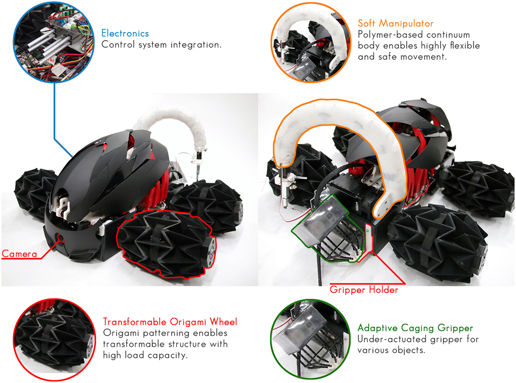
Figure 2. Overall view of SNUMAX and description of key components.
The key components of SNUMAX were made with a combination of soft, flexible materials, and rigid materials, including polymers, fabrics, films, springs, wires, plastics, and metallic components. The robot’s tendon-driven actuating systems are driven by DC motors (DCX series, Maxon motor Ag.). The body of SNUMAX is made of acrylic plates, acrylic rods, and a chassis, all made by 3D printing (Objet260, Stratasys Inc.) using ABS-like material.
SNUMAX was constructed with a modular design. The key components were modularized so that they could be easily replaced in the event of damage or malfunction. The internal parts of the key components themselves were also modularized to make it easy to perform minor repairs. For major failures, we simply replaced the involved key component. The modular design allowed us to be ready to make repairs during the challenge by preparing replacement parts in advance.
Transformable Origami Wheel
The transformable wheel allowed SNUMAX to accomplish the terrestrial scenario. The wheel can assume two final configurations: wider along its axis with small diameter and narrower along its axis with large diameter. Deformation of the wheel greatly increases maneuverability by enhancing the robot’s adaptability to various types of terrain. By adjusting the diameter of the wheel, it is possible to adjust the wheel’s shape and torque to achieve a balanced configuration that allows the robot to climb stairs and traverse rough terrain.
The transformable wheel was built using an origami-based soft robotics design. Wheels need to be able to endure their payload and absorb impact transferred from the ground. A wheel built from soft materials can provide deformability and absorb impact but will have difficulty enduring a high payload. In addition, wheel distortion caused by the softness of the material lowers the wheel’s mobility and hinders stable movement.
Our solution to the problem of creating a wheel from soft materials is to use origami patterning on the soft material. A wheel constructed of soft material that is embedded with hardened segments constrains the redundant degrees of freedom of the wheel, allowing it to maintain a circular shape even when high force is applied to it. The related researches of a transformable origami-based wheel are presented in previous studies (Lee et al., 2013a, 2014).
To create the transformable wheel, eight units of the waterbomb origami pattern are repeated in a circumferential direction to make a circular rim shape, and three units of the pattern are repeated in the axial direction to make the support structure (Figure 3A). To connect the wheel shaft to the wheel body, the edge of the wheel pattern was modified, and a special hub component was designed (Figure 3A).
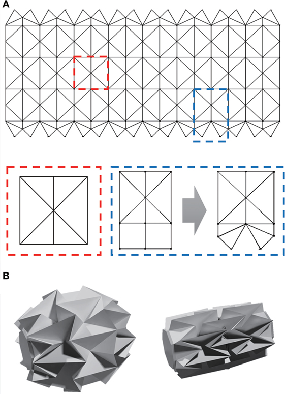
Figure 3. Origami pattern and assembled shape of the transformable wheel. (A) The entire pattern is composed of a repeated 3 × 8 unit pattern (known as the waterbomb pattern; red box). One end of the base pattern was modified to build a structure that connects to the shaft hub (blue box). (B) The diameter of the wheel structure can be changed by contracting both sides of the wheel.
The wheel facets were made from 0.3-mm PET film, and the fold lines consist of fabric. The PET was patterned via laser machining, and gelatin films were used to align the segments. The patterned PETs were wrapped up by fabric, and the whole structure was assembled using a sewing machine. The width of the complete wheel changes from 200 to 110 mm, and the radius changes from 100 to 230 mm. Each wheel can bear more than 10 kgf.
Transformation of the wheel is accomplished by changing the distance between the inner and outer wheel hubs via a basic wire–pulley mechanism. One end of the wire is attached to the outer hub by a clamping component, and the distance between the hubs increases or decreases as the pulley pushes or pulls the wire. To attach the wire firmly to the wheel and prevent it from twisting, a two-layered-wire structure and a special clamping component were used. Because the pulley broke frequently owing to the high tension that it needed to sustain, it too was given a modular design so that it could be quickly replaced during the challenge (Figure 4).
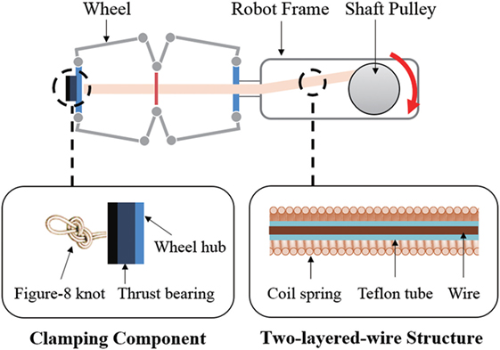
Figure 4. Schematic diagram of the wheel transformation mechanism. The shaft pulley pulls one side of the wheel, which changes the wheel’s diameter. A thrust bearing prevents the tendon from twisting, and a multi-layered wire structure protects the wheel from being worn out by friction.
The two-layered-wire structure consists of a Kevlar wire covered first by a Teflon tube and then by a coil spring. The coil spring has low bending stiffness, but relatively high torsional stiffness. This anisotropic characteristic allows the wire to be easily wound on the pulley and prevents it from becoming tangled, even when the wheel rotates. The Kevlar wire reinforces the coil spring’s stiffness and helps it to endure a large normal force during wheel deformation. The Teflon tube is positioned between the Kevlar wire and the coil spring sheath to prevent them from abrading each other.
The clamping component consists of a thrust bearing and a figure-eight knot. The thrust bearing keeps the wire structure from twisting, and the figure-eight knot guarantees strong bonding between the wire structure and the wheel. A figure-eight knot is the proper choice for this bonding, since, the more the wire is pulled, the tighter the knot becomes.
Polymer-Based Variable Stiffness Manipulator
To accomplish the tasks of the challenge’s manipulation scenario, the soft manipulator needed a flexible arm that could move flexibly and lift a 1-kg load 500 mm high while holding itself parallel to the ground. In addition, the manipulator needed to smoothly roll or bend tightly close to the robot for the terrestrial navigation part of the challenge. To fulfill these conditions, we developed the PVSM using a design inspired by the mammalian backbone (Figure 5). This design is a derivative of the dolphin robot’s variable stiffness tail fin (Park et al., 2014).
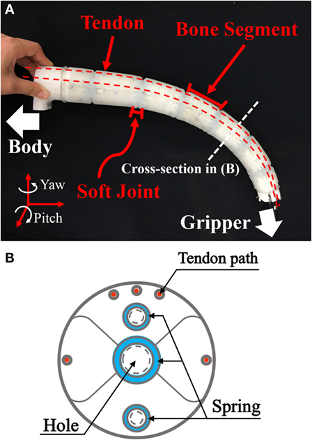
Figure 5. Design of the PVSM. (A) The manipulator is composed of soft joints and rigid “bone” segments and has five embedded tendon routes. (B) Cross-sectional view of the rigid “bone” segments of the manipulator. Holes near the circumference admit tendon wires, and two embedded springs constrain the pitch motion of the manipulator.
Soft manipulators are one of the most actively researched fields in soft robotics. There are a lot of different kinds of previous researches from continuum robots to soft robotic manipulators, and from micro scale to meter scale (Renda et al., 2012; Martinez et al., 2013; Paek et al., 2015; Ranzani et al., 2015). Also, there are efforts to control stiffness of the manipulator to improve versatility of continuum and soft manipulators (Jiang et al., 2012; Kim et al., 2013b; Santiago et al., 2015). To success the tasks in the grand challenge, a manipulator should have both softness and enough stiffness to deal with objects. Therefore, the PVSM consists of rigid segments analogous to vertebral bones and elastomer segments analogous to soft intervertebral joints, which are consecutively connected in a manner similar to the connections in the mammalian vertebral column. This mechanical design provides high degrees of freedom and variable stiffness to the manipulator, as well as the mechanical simplicity that is a hallmark of soft robotics.
The PVSM is operated by pulling its five tendons (cable part number 2014, Carl Stahl Sava Industry, Inc.). The two side tendons steer the PVSM, and the other three tendons stiffen the PVSM to compensate for loads (see Figure 3). Each tendon is actuated by a linear actuator. The tendons were surrounded by Bowden cables. The Bowden cables are intersections between the manipulator and linear actuators. Pulling the tendons asymmetrically causes bend motion of the PVSM. On the other hand, pulling the tendons symmetrically compresses the soft joints and changes their stiffness according to the properties of their constituent materials (Huh et al., 2012). Therefore, when the tendons are pulled symmetrically, there is no bending motion of the manipulator, but the stiffness of the manipulator increases by controlling the pulling force of the tendons. By controlling both the motion and the stiffness of the PVSM, we were able to pick up and place objects weighing up to 1 kg. However, the tendons often snapped when they were pulled tight enough to pick up a load of this size. Therefore, the tendons were replaced prior to executing the challenge’s manipulation scenario to ensure that the manipulator would perform well. In future, design optimization and new control schemes will help to increase the manipulator’s load capacity.
By anisotropically embedding springs into the PVSM joints, we enhanced joint strength and maintained flexibility. To lift a load, the PVSM needed to be adequately stiff in the pitching direction. To ensure that the robot is flexible enough to navigate obstacles, the PVSM needed low stiffness in the yaw direction. The anisotropically embedded springs enhance stiffness of the manipulator in pitch direction. In addition, the springs prevent axial twisting, to which the PVSM is vulnerable.
The PVSM has a tapered-radius design that minimizes bending caused by the weight of the manipulator and the payload. This design decreased the PVSM’s weight. The radii of the rigid segments were designed based on data from experimental trials varying the radius of the segments to modify PVSM strength and softness. This process was based on a previous parametric study of the relationship between the radius of a soft joint and its stiffness (Huh et al., 2012).
The rigid segments were 3D printed (3DISON, Rokit, Inc.) using polylactic acid (PLA). The segments are hollow to lighten the manipulator, and their top and bottom surfaces are bumpy to increase the total surface area, which helps increase the adhesive strength between the segments and the silicone joints. To assemble the PVSM, the segments were connected with torsional springs, and the gaps between them were filled with silicone (Ecoflex 0020, Shore A hardness 0020; Smooth-On, Inc.). The entire body was cured in one process using 3D-printed molds. We penetrated the manipulator with several holes to reduce its weight. To make tendon paths, we embedded Teflon tubes in the molds before curing and removed them after curing.
The final PVSM manipulator is composed of seven rigid segments. Its total length is approximately 450 mm (the minimum length to reach for the objects), and its radius is 35 mm at the end point and 50 mm at the root. The length of the elastic joints is approximately 7 mm.
Adaptive Caging Gripper
According to the rules of the challenge, the robot gripper was required to collect objects weighing a maximum of 1 kg that have been placed in a bounding box approximately 100 mm on each. The positions, shapes, and materials of the objects were not revealed until the day of the challenge. We developed five design criteria for the gripper based on these rules. First, the gripper had to be able to hold a 1 kg object. Second, the gripper needed to be as light as possible because the total carrying weight of the PVSM is the sum of the weights of the object and the gripper. Third, the gripper needs to get into the bounding box to grasp objects inside the box. Fourth, the gripper must be sand-proof to enable it to survive the terrestrial navigation scenario. Fifth, the gripper’s batteries must be strong enough to last for the whole the competition (i.e., for at least an hour).
Previously developed grippers can be divided into three categories: grippers with anthropomorphic hands (Liu et al., 2008) [e.g., the Shadow Dexterous Hand (Shadow Robot Company, 2016)], soft grippers with pneumatically actuated fingers [e.g., industrial grippers from Soft Robotics Inc. (2016)], and soft grippers that use a jamming mechanism (Amend et al., 2012). To meet the requirements for the manipulation scenario and to maximize the gripper’s performance, we developed a new type of soft gripper with a tendon-driven mechanism inspired by bird claws. The new design consists of a rectangular origami cage made of fabric and PET film with legs that terminate in claws attached at one end (Figure 6). The cage isolates the gripper’s electronics from sand. Inside the cage are two motors, one for z-axis actuation and the other to actuate the gripping motion, and two batteries, one for actuating both actuators and the other to power a camera. The camera allows the SNUMAX operator to see the robot’s grasping performance in real time. It can be connected to a smartphone via Wi-Fi. The gripper is 90 mm wide, 90 mm long, and 170 mm tall, and it weighs 201 g.
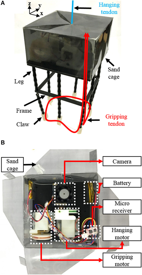
Figure 6. Adaptive caging gripper and its electronic components. (A) Appearance of the adaptive caging gripper. The hanging tendon, which moves grippers in the z-axis direction, is denoted by a blue line, and the gripping tendon path is denoted by a red line. (B) Electronic components of the gripper. The origami cage contains two DC motors, two batteries, one camera, and a micro receiver.
The gripper has eight legs as shown in Figure 7A. Before deciding to use the rectangular shape, we tried circular, hexagonal, and octagonal grippers because of adapting orientation between the gripper and the bounding box, while maximizing the griping ability. We finally settled on a rectangular shape because it could be readily sized to fit within the bounding box from which it would need to grasp various objects. At this point in the design process, the gripper had a z-axis structure with bearings for orientation. We changed this z-axis structure into a tendon–pulley system, which reduced the gripper’s weight and size, reduced z-axis rotational friction, and even gave us z-axis actuation.
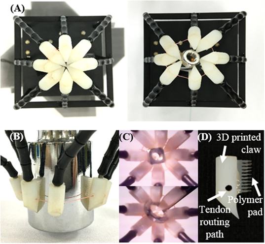
Figure 7. Design and performance of the claw. (A) Left, closed state of the claw. All claws are closed in one point. Right, claw gripping a small nut. (B) Claw gripping a large smooth-surfaced object. (C) Images of gripping captured by the embedded camera. (D) Claw design. The polymer pad is attached to the 3D-printed claw.
To increase the gripper’s adaptability to different object shapes and to decrease the number of actuators needed, we used an under-actuation tendon routing system and compliant legs. The under-actuation mechanism allows eight legs to be actuated with one tendon, as shown in Figure 6. To minimize friction between the tendon and its path, an important issue in tendon routing systems, Teflon tubes were embedded in the structure, and a symmetrical tendon path was formed. Also, to ensure compliance of the legs, a spring was used. The length of the spring had to change to form the grasping posture as shown in Figure 7A.
The gripper claws consist of a 3D-printed component and a polymer pad. The claw has a 45° angle, considering gripper with eight legs, so that the gripper can fully enclose the bottom of a grasped object (Figure 7D). Another important feature of the claw is its tendon routing path, consisting of embedded Teflon tubes, which minimize friction of the tendon. The shape of the claw is suitable for capturing small objects (Figure 7A), but not for big ones (Figure 7B), and the claw does not create enough friction to hold an object of any significant weight. Therefore, a polymer pad with spines, inspired by the Gecko pad (Kim et al., 2008), was added to the claw, as shown in Figure 7D. The polymer pads were molded from a laser-cut acrylic plate. These polymer pads drastically increased the friction of the claw and allowed the gripper to grasp even heavy objects with a smooth surface, as shown in Figure 7B. Figure 7C shows an example of what the operator can see via the embedded camera. In this case, the gripper has picked up a nut.
Electric Circuit
Figure 8A shows SNUMAX’s on-robot circuit board. SNUMAX has three dual motor drivers (Sabertooth 2 × 12, Dimension Engineering LLC.) for six DC motors (four for wheels and two for wheel deformation). The motor drivers communicate with the on-robot MCU (Arduino Due) by TTL serial communication. The shoulder of the manipulator is attached to a Dynamixel Pro motor (Robotis, Inc.). The Dynamixel Pro is driven by its own control board (OpenCM; Robotis, Inc.), and the board is controlled by the on-robot MCU. The five linear motors (L16-R; Actuonix, Inc.) that actuate the manipulator have embedded controllers. Pulse width modulation signals were used to control the linear motors. The signals were generated from the on-robot MCU (Figure 8C). To avoid signal noise and simultaneously actuate all five linear actuators, a 0.2-μF ceramic capacitor was inserted between the MCU and each linear actuator.
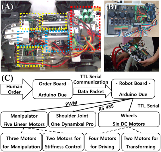
Figure 8. SNUMAX circuit board and operator’s controller and schematic diagram of the control signal. (A) Yellow squares indicate the dual motor drivers. Blue squares indicate two MCU boards. The red square indicates the electric power distribution area. (B) Photo of the operator’s controller. Control signals were packetized and transmitted by TTL serial communication protocol to the MCU board on the robot. (C) Schematic diagram showing the control signal flow.
Full activation of SNUMAX required both an 18 and a 7 V DC power source, which could be supplied by a tethered or an untethered power source. The tethered source uses a switched-mode power supply to supply 18 V of DC current and a power supply provided during the challenge to supply the 7 V DC current. For the untethered source, SNUMAX uses a battery pack that supplied both 18 and 7 V DC current.
Figure 8B shows the operator’s controller. Joysticks are used to maneuver SNUMAX, and knobs are used to deform the wheels. Switches control five linear actuators for the PVSM’s tendon-driven actuation system. Additional switches control auxiliaries, such as headlights. The joysticks are powered by three lithium-ion battery cells.
Design of the Robot
A 3D model of SNUMAX (Figure 9A) was produced by using a computer-aided 3D graphics rendering program (Rhinoceros 3D 5.0, Robert McNeel & Associates). The 3D computer graphic model was used to make a mold for the outer shells and ribs of SNUMAX. Thin shell pieces were 3D printed based on the graphic model and used as the molds. We used a vacuum forming machine to form the shells and ribs from PVC film. After trimming the resulting pieces and sanding their edges, we spray-painted the shells black and the ribs red (Figure 9B). We also covered the shells with a protective coating material. Finally, we bolted the ribs and shells together.
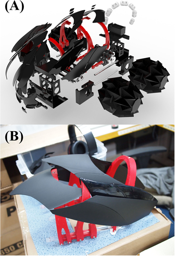
Figure 9. 3D model of SNUMAX. (A) Computer-aided 3D-rendered model. (B) Ribs and shells of SNUMAX.
In-House Experiments Conducted to Prepare for the Challenge
A month before the competition, we constructed test fields to the dimensions specified in the challenge rulebook and put prototypes of the robot through several test drives (Figure 10). For the terrestrial navigation scenario, we built an aperture and stairs of polystyrene boards and set up an obstacle course of acrylic pipes about 100 mm in diameter. The size of the aperture was 450 mm × 450 mm, and the height of the stairs was 50 mm. We tested SNUMAX’s ability to navigate in sandy terrain in a sandbox at a school playground located on our college campus.
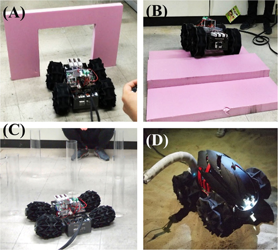
Figure 10. Sandbox testing of the prototype robot. (A) Passing through an aperture. (B) Climbing stairs. (C) Passing between unstable obstacles. (D) Sandbox test of the final challenge-ready robot.
For the manipulation scenario, we constructed test fields for the pick and place task and the arm-positioning task. We tested the robot’s ability to remove a variety of objects, including a 500-g weight, a water bottle, and a plastic ball, from a 100-mm acrylic cube and place them into an empty acrylic cube of the same dimensions. For the arm-positioning task, we fixed two types of rods (foam noodles and acrylic pipes) to the ground and confirmed that the PVSM could maneuver around both rigid and soft rods. We did not test the door opening task.
Performance During the Challenge’s Terrestrial Navigation Scenario
The terrestrial navigation scenario included four tasks: crossing sand terrain, passing through a small aperture, ascending and descending stairs, and passing between an array of unstable poles. To complete these tasks with high scores, the robot needed to be highly maneuverable and able to climb stairs and shrink to a small size while maintaining its mobility.
Crossing Sand Terrain
This task tested a robot’s maneuverability on rough terrain (Figure 11A). The test field included small bumps while robot enters and exits the sand box tile. Widening the robot’s wheels allowed it to climb over these bumps and cross the sand terrain on the first attempt. The granularity of the sand was fine in comparison to the diameter of the wheels and the depth of the sand was shallow in comparison to the wheel diameter, allowing SNUMAX to cross the sand box without becoming stuck.
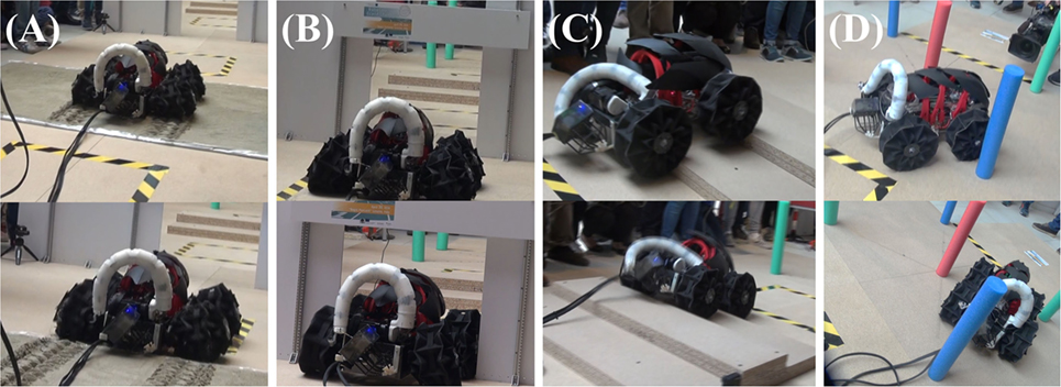
Figure 11. Performance during the four terrestrial navigation scenario tasks. (A) Crossing sand terrain: enlarging SNUMAX’s wheels allowed it to overcome a small bump and move on sand terrain. (B) Passing through a small aperture: shrinking SNUMAX’s wheels allowed it to pass through a small aperture. (C) Ascending and descending stairs: enlarging SNUMAX’s wheels allowed it to ascend and descend stairs. (D) Passing between unstable obstacles: the robot was carefully maneuvered between unstable poles without touching them while narrowing the wheels.
Passing through a Small Aperture
This task tested a robot’s shape-deforming abilities (Figure 11B). The aperture was square shaped. The size of the aperture was an important factor in scoring this part of the terrestrial navigation scenario: the score for passing the test was multiplied by the reductive ratio of the robot, which was calculated by dividing the maximum dimension of the front section of the robot by the length of one edge of the aperture. SNUMAX had a wide width for aperture. On the other hand, height of SNUMAX was not critical to pass the aperture. SNUMAX can shrink in width from 600 to 450 mm, which means that its reductive ratio is about 1.33. After the SNUMAX’s wheels were narrowed along the wheel axis, it passed through the test aperture within approximately 1.5 min.
Ascending and Descending Stairs
This task tested whether a robot has enough grip and torque to ascend and safely descend stairs. The test stairs had two 50-mm-high steps. When radii of SNUMAX’s wheels were enlarged and the drive train was maximally powered, it ascended and descended the stairs while overcoming the weight of the robot (Figure 11C).
Passing between Unstable Obstacles
This task tested a robot’s dexterity. Performing this task required a robot to shrink its body width to the same extent as was needed for the small aperture test and to exhibit sufficient maneuverability at this size to pass between an array of unstable cylinders (Figure 11D). The poles were attached to the ground by weak magnets and could be knocked down by the slightest touch. After SNUMAX’s wheels were fully shrunk, it completed the task without tipping over any poles, thanks to its steering mechanism.
Performance During the Challenge’s Manipulation Scenario
The manipulation scenario included three tasks: picking up and placing a variety of objects weighing up to 1 kg, moving the robot’s arm to placing its end effector at specific locations, and opening a door. A referee chose the order in which these tasks were performed, in contrast to the terrain navigation scenario, whose tasks were in a fixed order. Successfully completing the manipulation tasks required SNUMAX’s manipulator to be (a) strong enough to pick up and hold objects weighing up to 1 kg and to open a door and (b) soft enough, flexible enough, and long enough to position its gripper at all the targeted locations while avoiding objects placed in its way.
Picking and Placing Objects
This task tested whether a robot could pick up objects from a starting point and place them in a basket 500 mm away from the starting point. The robot’s gripper had to hold the objects continuously; dropping an object and picking it back up was not allowed.
The target objects were revealed during the practice session the day before the challenge: a 500-mL plastic bottle filled with water, an ice cream cone, a 100 mm × 50 mm square plastic food container, and a 100-mm-long combination wrench (Figure 12A). SNUMAX was the only robot in the competition that was able to grasp and place all four objects, thanks to the adaptive caging gripper’s claws and friction pads. Moreover, the gripper was able to hold the heaviest object (the water bottle) without buckling or breaking it.
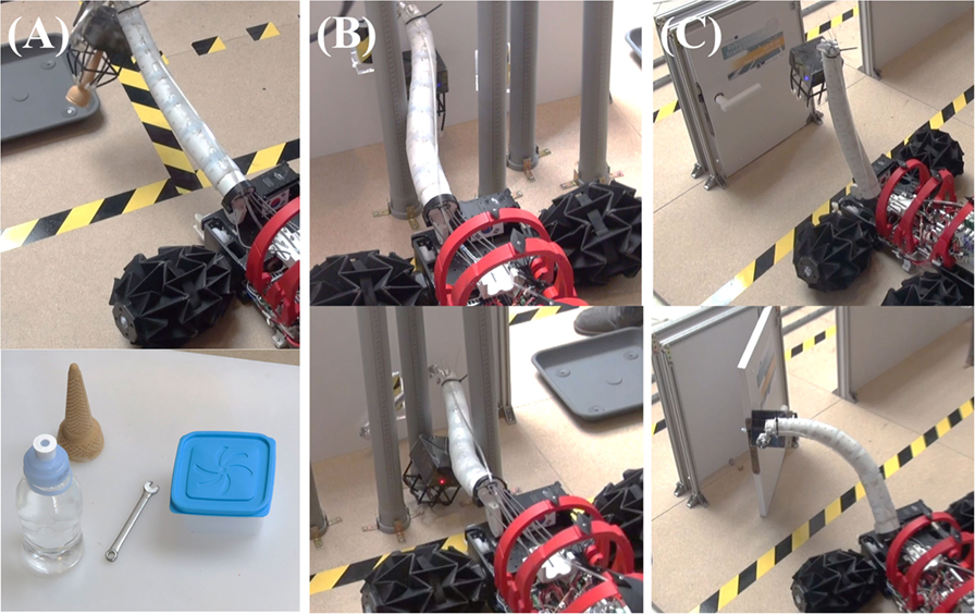
Figure 12. Performance during the three manipulation scenario tasks. (A) Object pick and place task: SNUMAX picked up and placed all four objects with its PVSM and adaptive caging gripper. (B) Arm-positioning task: SNUMAX’s PVSM reached all three target positions. (C) Door opening task: Lifting the PVSM while pulling the door allowed SNUMAX to manipulate the door knob and open the door.
Arm Positioning
This task tested the dexterity and flexibility of a robot’s manipulator. The manipulator had to place its end effector at three different target places on a wall, each at a different height (Figure 12B). To reach two of the targets, the manipulator maneuvers around increasingly complex sets of obstacles. SNUMAX’s PVSM proved to be nimble and long enough to touch all of the targets, and it easily avoided the obstacles. Varying the stiffness of the PVSM by manipulating its linear actuators overcame the manipulator’s tendency to be deflected by its weight and helped the PVSM to hold its position after being maneuvered through the obstacles.
Door Opening
This task tested the strength of a robot’s end effector and manipulator and the handling ability of the end effector (Figure 12C). SNUMAX’s adaptive caging gripper was able to catch the door knob between its claws. After the gripper caught the door knob, the PVSM was stiffened, and the shoulder of the manipulator was lifted to turn the door knob while the robot was moved backward to pull open the door. Because the gripper was built to hold up to 2 kg of payload, it had no difficulty holding reaction force at the door knob without breaking. This was the first manipulation scenario task for SNUMAX.
Discussion
SNUMAX won first place in the competition, taking about 7 min and 45 s to complete the terrestrial navigation scenario and about 13 min to complete the manipulation scenario. SNUMAX was the only robot that attempted and completed all the tasks from both scenarios. This victory was achieved because the components of SNUMAX that interact with the environment – its wheels, manipulator, and gripper – are soft and adaptive. SNUMAX is a state-of-the-art robot that demonstrates the potential of robots with soft components to affordably solve problems in real-life environments.
Notwithstanding its performance in the competition, aspects of SNUMAX’s performance could be improved. The payload of the wheel and the robustness of the transformation mechanism are the main performance factors for the origami transformable wheel. The wheel’s payload could be enhanced by using improved manufacturing processes and advanced materials to prevent wheel collapse from failure of its rigid facets and delamination of the rigid and flexible layers. The weakest part of the wheel transformation mechanism is the wire structure, which can be snapped by abrupt shear stress where the wheel connects to the body. Replacing the material used to make the wire structure or supplementing the structure with, for example, a linear guide component would solve this problem.
The PVSM could be improved by design optimization and new control strategies. Further study of the relationship between the stiffness of the soft joints and the shape of the rigid segments could lead to optimizations that would improve performance and lead to enhanced ability to vary the stiffness of the manipulator. Optimization of the tendon paths and the location and stiffness of the springs could improve bending performance and reduce sagging of the manipulator. In future, human control of the PVSM’s stiffness could be supplemented by feedback control according to the dealing load and the target manipulation tasks.
SNUMAX was the only robot in the competition that could grasp all of the task objects. Its under-actuation mechanism and soft structure using springs played important roles in its ability to adapt to objects of varying shapes. Claws with a polymer pad were key to grasping objects of all sizes, from small and light to big and heavy. Minimizing the total weight of the gripper was important in increasing the dexterity of the PVSM, which enabled precise orientation of the gripper. The adaptive caging gripper’s grasping ability and capacity could be further improved by design optimization. Modifying the length of the legs and the position of the frame will be vital factors for improving grasping performance, and grasping capacity will be influenced by the design and material composition of the claws.
In the future, robots will permeate everyday life. As soft robotics researchers, we believe that soft robotics has the potential to accelerate this change. We hope that what we have achieved by participating in the RoboSoft Grand Challenge will help the field expand rapidly in this direction.
Author Contributions
J-YL and DP integrated components as system and built electric controls of the robot. BK and S-MB developed the adaptive gripper of the robot. W-BK and W-YC developed the PVSM of the robot. D-YL and H-JJ fabricated the transformable origami wheels and drive train. J-RS designed body works and shells of the robot. K-JC handled and coordinated the development process.
Conflict of Interest Statement
The authors declare that the research was conducted in the absence of any commercial or financial relationships that could be construed as a potential conflict of interest.
Acknowledgments
Thanks to Jae-Hyeok Choi, Sung-Sik Yun, Sang-Hoon Kim, and Harim Son for assistance in preparing for the challenge.
Funding
This work was supported by the Technology Innovation Program (10051287, Development of fundamental technology of soft robotics for advanced soft gripper), funded by the Ministry of Trade, Industry & Energy (MOTI, Korea). This research was supported by a grant to the Bio-Mimetic Robot Research Center, funded by the Defense Acquisition Program Administration under the grant number UD130070ID. This material is based on research sponsored by the Air Force Research Laboratory, under agreement number FA2386-13-1-4019. The U.S. Government is authorized to reproduce and distribute reprints for Governmental purposes notwithstanding any copyright notation thereon.
Supplementary Material
The Supplementary Material for this article can be found online at http://journal.frontiersin.org/article/10.3389/frobt.2016.00063
References
Albu-Schaffer, A., Eiberger, O., Grebenstein, M., Haddadin, S., Ott, C., Wimbock, T., et al. (2008). Soft robotics. IEEE Robot. Autom. Mag. 15, 20–30. doi: 10.1109/MRA.2008.927979
Amend, J. R., Brown, E. M., Rodenberg, N., Jaeger, H. M., and Lipson, H. (2012). A positive pressure universal gripper based on the jamming of granular material. IEEE Trans. Robot. 28, 341–350. doi:10.1109/TRO.2011.2171093
Chen, S.-C., Huang, K.-J., Chen, W.-H., Shen, S.-Y., Li, C.-H., and Lin, P.-C. (2014). Quattroped: a leg–wheel transformable robot. IEEE ASME Trans. Mechatron. 19, 730–742. doi:10.1109/TMECH.2013.2253615
Huh, T. M., Park, Y.-J., and Cho, K.-J. (2012). Design and analysis of a stiffness adjustable structure using an endoskeleton. Int. J. Precis. Eng. Manuf. 13, 1255–1258. doi:10.1007/s12541-012-0168-2
In, H., Kang, B. B., Sin, M., and Cho, K.-J. (2015). Exo-glove: a wearable robot for the hand with a soft tendon routing system. IEEE Robot. Autom. Mag. 22, 97–105. doi:10.1109/MRA.2014.2362863
Jiang, A., Xynogalas, G., Dasgupta, P., Althoefer, K., and Nanayakkara, T. (2012). “Design of a variable stiffness flexible manipulator with composite granular jamming and membrane coupling,” in 2012 IEEE/RSJ International Conference on Intelligent Robots and Systems (IROS) (Vilamoura), 2922–2927.
Kang, B. B., Lee, H., In, H., Jeong, U., Chung, J., and Cho, K.-J. (2016). “Development of a polymer-based tendon-driven wearable robotic hand,” in 2016 IEEE International Conference on Robotics and Automation (ICRA) (Stockholm), 3750–3755.
Kim, S., Laschi, C., and Trimmer, B. (2013a). Soft robotics: a bioinspired evolution in robotics. Trends Biotechnol. 31, 287–294. doi:10.1016/j.tibtech.2013.03.002
Kim, Y.-J., Cheng, S., Kim, S., and Iagnemma, K. (2013b). A novel layer jamming mechanism with tunable stiffness capability for minimally invasive surgery. IEEE Trans. Robot. 29, 1031–1042. doi:10.1109/TRO.2013.2256313
Kim, S., Spenko, M., Trujillo, S., Heyneman, B., Santos, D., and Cutkosky, M. R. (2008). Smooth vertical surface climbing with directional adhesion. IEEE Trans. Robot. 24, 65–74. doi:10.1109/TRO.2007.909786
Lee, D.-Y., Kim, J.-S., Kim, S.-R., Koh, J.-S., and Cho, K.-J. (2013a). “The deformable wheel robot using magic-ball origami structure,” in ASME 2013 International Design Engineering Technical Conferences and Computers and Information in Engineering Conference (Portland, OR), V06BT07A040.
Lee, D.-Y., Kim, S.-R., Kim, J.-S., Park, J.-J., and Cho, K.-J. (2013b). “Fabrication of origami structure using pattern enclosed composite (PEC),” in International Conference on Control, Automation and Systems (Gwangju), 313–315.
Lee, D.-Y., Kim, J.-S., Park, J.-J., Kim, S.-R., and Cho, K.-J. (2014). “Fabrication of origami wheel using pattern embedded fabric and its application to a deformable mobile robot,” in 2014 IEEE International Conference on Robotics and Automation (ICRA) (Hong Kong), 2565.
Liu, H., Wu, K., Meusel, P., Seitz, N., Hirzinger, G., Jin, M. H., et al. (2008). “Multisensory five-finger dexterous hand: the DLR/HIT hand II,” in 2008 IEEE/RSJ International Conference on Intelligent Robots and Systems (Nice), 3692–3697.
Martinez, R. V., Branch, J. L., Fish, C. R., Jin, L., Shepherd, R. F., Nunes, R. M. D., et al. (2013). Robotic tentacles with three-dimensional mobility based on flexible elastomers. Adv. Mater. 25, 205–212. doi:10.1002/adma.201203002
Mazzolai, B., and Mattoli, V. (2016). Robotics: generation soft. Nature 536, 400–401. doi:10.1038/536400a
Nagatani, K., Kuze, M., and Yoshida, K. (2007). Development of transformable mobile robot with mechanism of variable wheel diameter. JRM 19, 252–257. doi:10.20965/jrm.2007.p0252
Paek, J., Cho, I., and Kim, J. (2015). Microrobotic tentacles with spiral bending capability based on shape-engineered elastomeric microtubes. Sci. Rep. 5, 10768. doi:10.1038/srep10768
Park, Y.-J., Huh, T. M., Park, D., and Cho, K.-J. (2014). Design of a variable-stiffness flapping mechanism for maximizing the thrust of a bio-inspired underwater robot. Bioinspir. Biomim. 9, 36002. doi:10.1088/1748-3182/9/3/036002
Ranzani, T., Gerboni, G., Cianchetti, M., and Menciassi, A. (2015). A bioinspired soft manipulator for minimally invasive surgery. Bioinspir. Biomim. 10, 35008. doi:10.1088/1748-3190/10/3/035008
Renda, F., Cianchetti, M., Giorelli, M., Arienti, A., and Laschi, C. (2012). A 3D steady-state model of a tendon-driven continuum soft manipulator inspired by the octopus arm. Bioinspir. Biomim. 7, 25006. doi:10.1088/1748-3182/7/2/025006
RoboSoft CA. (2016). RoboSoft Grand Challenge. Available at: http://robosoftca.eu/
Rus, D., and Tolley, M. T. (2015). Design, fabrication and control of soft robots. Nature 521, 467–475. doi:10.1038/nature14543
Santiago, J. L. C., Walker, I. D., and Godage, I. S. (2015). “Continuum robots for space applications based on layer-jamming scales with stiffening capability,” in 2015 IEEE Aerospace Conference (Montana), 1–13.
Shadow Robot Company. (2016). Shadow Dexterous Hand™. Available at: http://www.shadowrobot.com/
She, Y., Hurd, C. J., and Su, H. J. (2015). “A transformable wheel robot with a passive leg,” in 2015 IEEE/RSJ International Conference on Intelligent Robots and Systems (IROS) (Hamburg), 4165–4170.
Soft Robotics Inc. (2016). Soft Robotic Grippers. Available at: http://www.softroboticsinc.com/
Keywords: SNUMAX, RoboSoft Grand Challenge, transformable origami wheel, polymer-based variable stiffness manipulator, adaptive caging gripper
Citation: Lee J-Y, Kang BB, Lee D-Y, Baek S-M, Kim W-B, Choi W-Y, Song J-R, Joo H-J, Park D and Cho K-J (2016) Development of a Multi-functional Soft Robot (SNUMAX) and Performance in RoboSoft Grand Challenge. Front. Robot. AI 3:63. doi: 10.3389/frobt.2016.00063
Received: 31 July 2016; Accepted: 04 October 2016;
Published: 18 October 2016
Edited by:
Marcello Calisti, Sant’Anna School of Advanced Studies, ItalyReviewed by:
Federico Renda, Khalifa University, United Arab EmiratesMaria Elena Giannaccini, University of Bristol, UK
Copyright: © 2016 Lee, Kang, Lee, Baek, Kim, Choi, Song, Joo, Park and Cho. This is an open-access article distributed under the terms of the Creative Commons Attribution License (CC BY). The use, distribution or reproduction in other forums is permitted, provided the original author(s) or licensor are credited and that the original publication in this journal is cited, in accordance with accepted academic practice. No use, distribution or reproduction is permitted which does not comply with these terms.
*Correspondence: Kyu-Jin Cho, a2pjaG9Ac251LmFjLmty