 Iiro Harjunkoski
 Reinhard Bauer
- ABB Corporate Research, Industrial Software and Applications, Ladenburg, Germany
In the development and deployment of production scheduling solutions, one major challenge is to establish efficient information sharing with industrial production management systems. Information comprising production orders to be scheduled, processing plant structure, product recipes, available equipment, and other resources are necessary for producing a realistic short-term production plan. Currently, a widely accepted standard for information sharing is missing. This often leads to the implementation of costly custom-tailored interfaces, or in the worst case the scheduling solution will be abandoned. Additionally, it becomes difficult to easily compare different methods on various problem instances, which complicates the re-use of existing scheduling solutions. In order to overcome these hurdles, a platform-independent and holistic approach is needed. Nevertheless, it is difficult for any new solution to gain wide acceptance within industry as new standards are often refused by companies already using a different established interface. From an acceptance point of view, the ISA-95 standard could act as a neutral data-exchange platform. In this paper, we assess if this already widespread standard is simple, yet powerful enough to act as the desired holistic data exchange for scheduling solutions.
Introduction
The scope and complexity of scheduling problems are continuously increasing due to the more established and efficient solution technologies and increased popularity and need to improve the profitability of industrial production. Trends such as enterprise-wide optimization (EWO) (Grossmann, 2005) foster more integrated problems across business functions. Most typical examples connect supply-chain management and production control aspects with the planning and scheduling (P&S) function. This results in larger problem instances, more complex data, and mathematical models making the solution landscape in general more complex (see for instance Chu and You, 2012; Engell and Harjunkoski, 2012; Zhuge and Ierapetritou, 2012). Traditionally, the production targets of a plant have been defined by enterprise resource planning (ERP) systems, which also in some cases have determined at least a rough production schedule for the plant floor. The feasibility of a schedule is typically ensured by a manufacturing execution system (MES) or collaborative production management (CPM) suite. These systems ensure that the production targets can actually be realized, include detailed planning with finite resources, and take process disturbances into account. Having real-time access to the plant floor, they further coordinate the detailed resources and host the main activities to realize the production, such as dispatching, tracking, visualization, and data collection and -analysis.
In this regard, it is very important to efficiently transfer and share the data and the information collected between a production management system environment, containing a multitude of functions, and the scheduling solution. If the scheduling solution, responsible for the tactical short-term planning of the production process, can be easily plugged into the overall solution landscape, this will greatly help to test and deploy new solutions of real problems in the process industries more efficiently. From a technical perspective, a platform-independent, holistic integration approach that requires configuration through parameters instead of customization by programing is desired to support easy integration in the production environment. If also applicable to a scheduling solution, this would offer a broad applicability, capturing most scheduling problems that occur in practice.
A number of scientific journal papers have discussed the identified gap between industry and academia (Henning, 2009; Harjunkoski, 2012) and the hurdles to deploy theoretical results in practice. The target is to define a standard way to plug-in a scheduling solution into a production management environment in order to ensure also the practical usability of the best research results. In another research line, Muñoz et al. (2013) presents an ontological framework to support a sequential optimization of problems from different decision levels by following a hierarchical approach, where also ANSI/ISA-88 and -95 standards are reflected. Muñoz et al. (2014) further uses the approach to generate mathematical models in the domain of enterprise and chemical processes. Framinan and Ruiz (2012) addresses successful strategies for the development and deployment of scheduling solutions and in Harjunkoski et al. (2014) many deployment aspects and lessons learned from the industry are discussed.
Here, we do not focus on analyzing the decision components of a hierarchy in the supply chain but assume that the decisions taken on the scheduling level are well defined. The main challenge is how to enable the data flow between the scheduling and surrounding components. We believe that a standardized approach which is efficient because it is widely understood has been jointly developed and is a neutral component, which increases the likelihood of a broader acceptance. The ANSI/ISA-95 standard (ANSI/ISA-95.00.03-2005, 2005) has been created by a neutral standardization committee, consisting of company and university members. ISA stands for International Society of Automation and considers all levels of process automation from the controller (device) level to the long-term planning in ERP systems. ANSI is the short name for American National Standards Institute, which launched the development of the ISA-95 standard in the 1990s, which has thereafter been approved as an international standard (known as IEC 62264). The official definition1 is: “ISA-95 is the international standard for the integration of enterprise and control systems. ISA-95 consists of models and terminology that can be used to determine which information has to be exchanged between systems for sales, finance and logistics, and systems for production, maintenance, and quality.” Thus, the standard is very broad and does not limit itself to production scheduling but covers many other business functions. This also means that there is no unique way to use the standard.
Simplistically said, the ISA-95 standard is designed for top-down information flow and it is rather straightforward to transmit/dispatch the main information of an already computed schedule to the shop floor using the standard. On the other hand, because of the top-down structure it is not fully straightforward how to provide all the information necessary to perform the scheduling actions. Some decisions are assumed to have been taken on a higher level and information such as sequence-dependent change-over times, release, and due dates of production orders are not directly covered by the core data elements (Harjunkoski et al., 2013). Naturally, scheduling needs are often very case-specific and this fact may hit the boundaries of a standard. Here, we try to adopt the standard in a way that fulfills the requirements for the most common scheduling problems.
Perhaps the most compact systems view of the ISA-95 standard is provided by the Purdue Reference Model, shown in Figure 1. The dashed line indicates the border between ERP and control system, but this can vary from case to case. The model shows that scheduling interacts closely with production control and lists the main information that is exchanged between the different components. Typical information flows are: scheduled orders are passed to the control layer, and the control system returns the production response and information about the production capability. The ISA-95 standard comprises material, personnel, equipment, and other information that may be required when defining a scheduling model. As each additional resource makes the scheduling task more complex, only those that are absolutely necessary in the scheduling (optimization) step should be provided. Many other decisions can be done afterwards as a post-processing activity based on the determined schedule. The ISA-95 standard does not per se dictate exactly how to use the standard but provides good guidelines and a structure for hosting the data exchange between production systems in a neutral, systematic, and standardized manner. This can significantly reduce the efforts in designing a scheduling system SW-architecture.
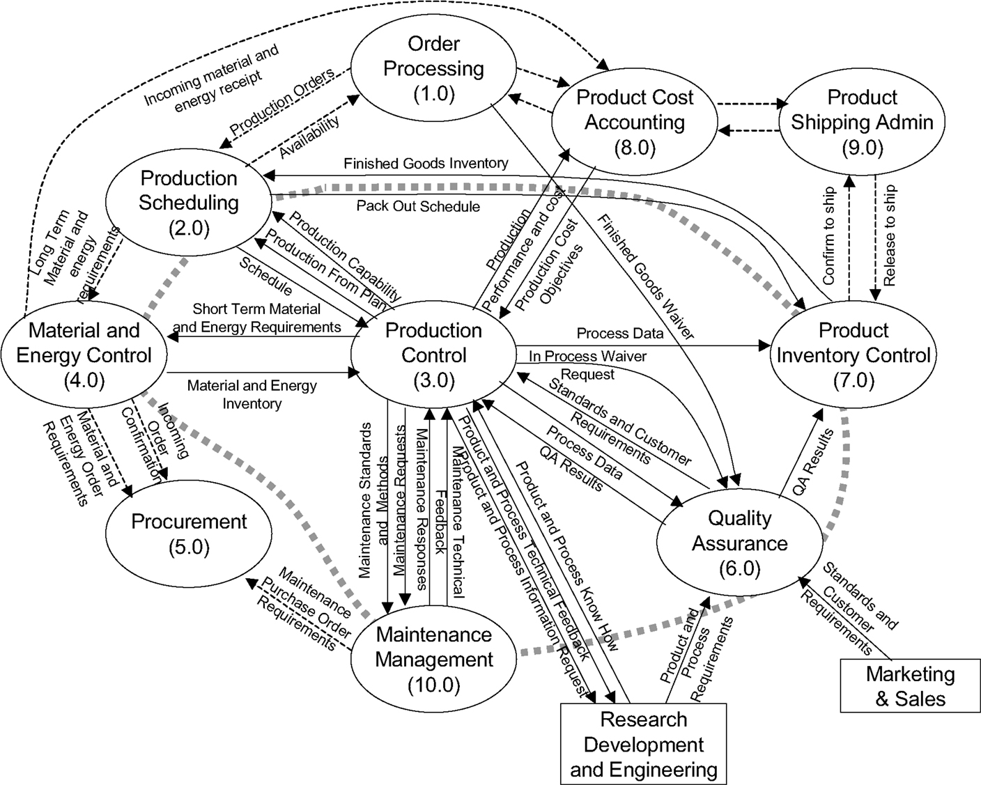
Figure 1. The Purdue reference model for ISA-95 (source: ANSI/ISA-95).
Business to manufacturing markup language (B2MML) is the implementation of the ISA-95 standard providing the corresponding extended markup language (XML) schemas. These files accurately define the structure of the exchanged information. This makes it relatively easy to be plugged-in into different software solutions, as many programing languages provide strong XML-support with automated syntax checking. However, there is still great degree of freedom left when actually implementing B2MML in a manufacturing environment: application-specific parameters and properties need to be defined, restrictions to the B2MML-standard have to be stated, and the semantic of the exchanged data has to be agreed-upon. Nevertheless, in comparison to other XML-based approaches (e.g., implementations based on ontologies) the ANSI/ISA-95 is already an accepted standard that is widely implemented in the industry and provides a well defined and commonly agreed data model.
The contribution of this paper is to assess the feasibility of using the ISA-95 standard for transferring input/output data to and from a scheduling solution. We propose how to apply the standard for a relatively generic set of scheduling problems. Along the definitions, we will use a simplified but still realistic example case to illustrate the use of the standard. We show that for the selected case-study, ISA-95 is a good choice. This gives other researchers in industry or academia a better impression on how to apply ISA-95 for data exchange in scheduling. This way, our work takes out risk of new projects on the topic and should further foster research.
Example Process
In order to make the following presentation clearer, we define a batch process to be used as a concrete example for the definition of the ISA-95 elements, their roles, and data contents. Our main focus is on batch-type of processes but the ISA-95 standard does not limit itself to batch processes. The example batch process is shown in Figure 2. It contains three consecutive processing steps: mixing, reaction, and packaging. Each step has a different number of parallel equipment, one of which has to be chosen when producing a specific product. The default processing path is physically unrestricted (each pair of equipment can be connected), but naturally depends on the product type. In our example, the raw materials are fed at the beginning of the first processing step. In other applications, there may be additional consumables such as electricity or water fed into any of the processing steps. These can be product or batch-specific or generic. For instance, a batch of 200 liters may need only a fraction of the amount of electricity than a batch of 1000 liters at the mixing stage. In order to clarify these differences, we assume three main products: A, B, and C. The requirements of these products are shown in the Tables 1–3. For illustrative purposes, let us assume that product A cannot use the packaging machine 3.
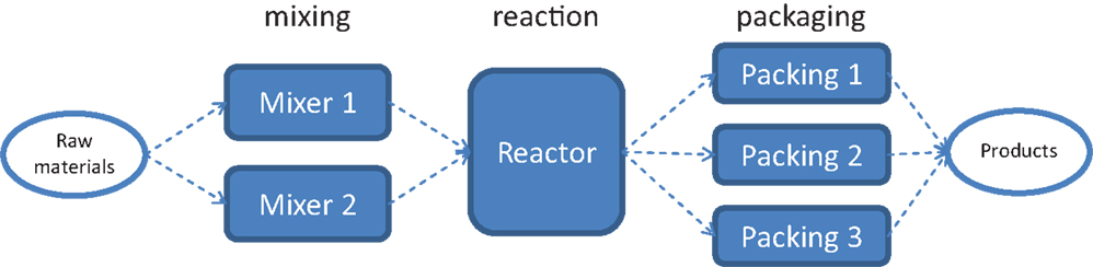
Figure 2. Example process comprising three production stages.
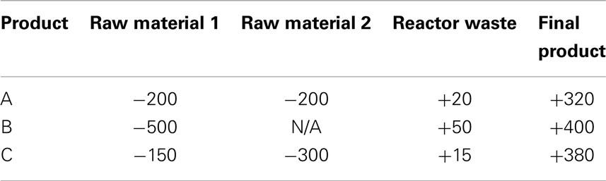
Table 1. Material requirements (−) and production (+) in kilograms.
In this example, all products need all stages but the equipment suitability may be restricted as shown by the tables below, where N/A means that the equipment or material is not needed nor considered for the product. Note that, for instance, in Table 1, only the materials relevant for optimization are shown.
Table 2 shows the durations of each processing stage, which are based on the equipment choice. Naturally, such fixed duration tables are static but if provided by a system they can always be updated to the best estimated values.
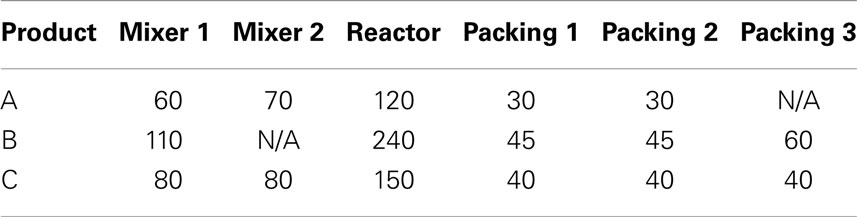
Table 2. Duration of processing steps (minutes).
In a similar way, Table 3 shows the electricity consumptions on specific equipments. This could be given also as energy (kilowatt hour), but here we assume an average continuous consumption and, if needed, the total energy needed can be easily calculated by multiplying the effect by the duration. Having more information at hand, this information could also be made more detailed, e.g., by providing a curve showing step-wise consumption.
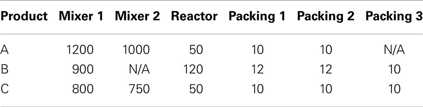
Table 3. Electricity requirements (continuous consumption in kilowatts).
Furthermore, a setup/cleaning time of 15 min is assumed for each equipment, regardless of the production sequence. We also assume that personnel will always be available to fulfill the production and do not explicitly consider it in the optimization. Nevertheless, for illustrative purposes, let us assume that we have three mixer operators: MixerOperator 1 can only operate Mixer 1, MixerOperator 2 can operate both mixers, and MixerOperator 3 can only operate Mixer 2.
Based on this information, it is now possible to define the corresponding ANSI/ISA-95-based XML files for the chosen example process.
ISA-95 Implementation of the Presented Example
Having defined most of the necessary data for scheduling the process, in this section we present the corresponding ISA-95 implementation of the data. B2MML contains several complex XML-elements, which comprise all the necessary information providing a generic, common, and extendable platform for data exchange between a scheduling component and the manufacturing environment, e.g., MES or CPM. The B2MML elements that need to be provided are (corresponding schema files of version 5 of the standard are shown in brackets):
• ProcessSegmentInformation (B2MML-V05-ProcessSegment.xsd)
• EquipmentInformation (B2MML-V05-Equipment.xsd)
• MaterialInformation (B2MML-V05-Material.xsd)
• PersonnelInformation (B2MML-V05-Personnel.xsd)
• OperationsCapability (B2MML-V05-OperationsCapability.xsd)
• OperationsDefinitionInformation (B2MML-V05-Operations Definition.xsd)
• OperationsSchedule (B2MML-V05-OperationsSchedule.xsd)
• OperationsResponse (B2MML-V05-OperationsPerformance.xsd)
The information flow is shown in Figure 3. It should be highlighted that the ISA-95 standard focuses purely on the data/information exchange and is completely independent on the actual scheduling algorithm. The information for scheduling may also contain rules, e.g., dependencies between subsequent production stages such as “the packing step may only start 20 min after the reaction step has finished,” which must be correctly implemented in the corresponding scheduling algorithm.
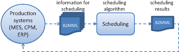
Figure 3. Data flow between scheduling and production systems.
It should also be pointed out that the data are normally provided by several systems or applications and collected into a production management system that then passes it forward to the scheduling. Necessary inputs are typically production recipes (often managed by ERP), current situation at the plant floor (MES or distributed control system), maintenance needs (maintenance management), equipment status (asset management), etc. All data elements do not exist in the basic standard, so it is necessary to further adapt it according to flexibility provided by the standard. In the following subsections, we propose how to structure the different B2MML elements and briefly explain and reflect them using the above example process.
The Production Sequence: ProcessSegmentInformation
Process segments constitute a blueprint for the execution-sequence of a product’s production steps. The process segments are defined here with possible additional information. For the flow-shop example above, we only need to list the main processing stages, as well as possible parameters that are generic and apply for all cases. The B2MML tree structure is shown in Figure 4. Here, the main ID and description are just for information and can be selected based on the user preference (e.g., ID = “Factory A,” description = “define main production steps”). The same applies to most ID elements, but it might be helpful to always define readable and understandable identifiers as this makes possible debugging or generation of overviews easier. In the end, B2MML and XML are text based (human readable). The ProcessSegment is the main element and typically there exists one instance per processing step. Its main sub-element is EquipmentSegmentSpecification, which just lists the equipment classes by ID that are necessary for executing the step. If necessary, it is also possible to define some dependencies where the dependency (e.g., “after end”) to another process segment is specified.
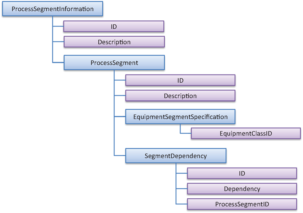
Figure 4. ISA-95 information on process segments.
The blue slightly larger rectangles in Figure 4 are complex structures containing sub-elements, whereas the smaller ones are just tags that can be simply used in the style <ID>mypreferredID</ID>. The complex structures can mostly be repeated unlimited amount of times, even if they are here displayed only once to clarify the structure. In this particular example, there would be three process segments “mixing,” “reaction,” and “packaging.” Each of them contains an equipment segment specification element, where one or more entries of the type equipment class ID, e.g., “mixers” are collected. The segment dependency element indicates in typical flow-shop problems that the previous production step of a task must be finished before the next one may start. In this case, dependency within the “packaging” section could be “AfterEnd” and the referring process segment ID would be “reaction” to denote that packaging of a production order or task may only begin after the reaction step has finished. A complete XML-example of this and all the other examples are shown in Supplementary Material.
General Information on Equipment: EquipmentInformation
The information about the equipment in the production facility follows exactly the same logic. Here, the existing equipment is collected with relatively little information (see Figure 5). The ID is always mandatory and must be unique for each B2MML element in order to correctly identify the element, whereas the optional description element is free text with the purpose of only providing clarity or some useful information for the human reader. In the main Equipment element, we simply want to know which equipment are available (ID) and some specific properties that they may have. The ISA-95 standard does not suggest any property names (IDs) but here at least two properties can be useful: “SetupTime” and “AvailableFrom.” The former one refers to a setup time that is equipment-specific and always must be taken into account independent of the production sequence. The latter property can be used to indicate that an equipment can be used for production only after a given date, for instance, due to a longer maintenance action. It is also important to provide a class ID in case the equipment is part of a larger group of equipment that offer similar type of functionalities or has certain common properties. Also, the ProcessSegment structure shown in the previous section must be able to refer to an equipment class ID.
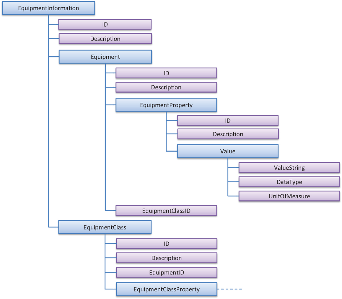
Figure 5. ISA-95 information on equipment.
In this particular case, we define all pieces of equipment (creating an Equipment element for each of them), for instance, with the IDs “mixer 1”, “mixer 2”, and their respective EquipmentClassID “mixers.” EquipmentClass information may alternatively be used to contain information about classes of Equipments and may contain the list of equipment belonging to the class.
Information on Material: MaterialInformation
The material information is provided in a similar manner, see Figure 6. Again, the generic ID and description may be used for the main element. One possibility is to simply list the material to be considered through the MaterialDefinition elements. The provided MaterialDefinitionProperties can be used to, for instance, indicate an initial material inventory status, as well as, the allowed minimum and maximum limits for the material storage. It is important to note that energy forms such as gas or electricity should also be treated through the MaterialInformation structure. For these, a maximum limit can also refer to the upper limit of simultaneous consumption. Defining the MaterialClassID is very helpful in classification of the materials. It can either be defined under the MaterialDefinition or under the MaterialClass structure, where the MaterialDefinitionID can simply be listed under the corresponding class.
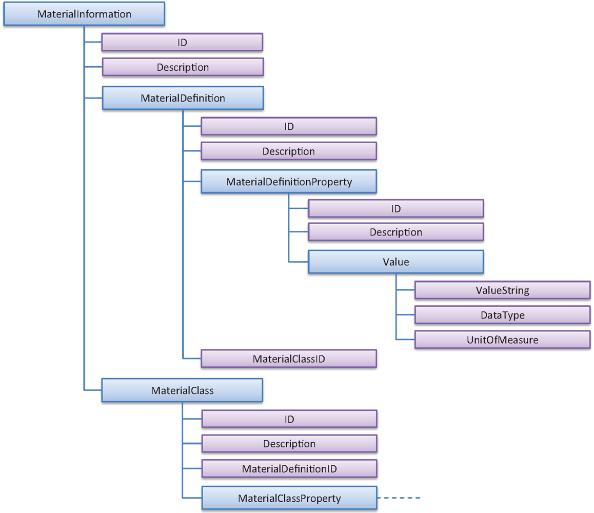
Figure 6. ISA-95 information on material.
In the discussed example, the main material to be considered is “electricity,” which could be classified under a material class “utilities.” Other important classes are “raw materials,” “final products,” and “waste.” This allows us to specify parameters, track material consumption, and production and if needed use them in the optimization. Often, material is considered to be unlimited and thus not included into the scheduling optimization step mainly due to modeling or numerical complexities that it raises. In this case, a material property can indicate whether it is relevant for the optimization, for instance, using a Boolean property “UseInOptimization.” Even if a material is not relevant for the optimization, the information can be used for post-processing calculations to, for instance, track the material usage, know the cost of the material, or estimate the intermediate storage levels during the planned schedule.
Information on Personnel: PersonnelInformation
For typical production scheduling problems, personnel is normally not considered in detail as it can be assumed that equipment have assigned operators. Nevertheless, in project planning or manual labor-intensive production steps, it may be critical to account for the individual employees already during the optimization step. The level of detail of the personnel may vary and, for instance, the working hours or even vacation plans of key people may be needed for the daily production planning. In general, the information about the personnel follows exactly the same logic as for material and the data entries are the same. See the overview in Figure 7.
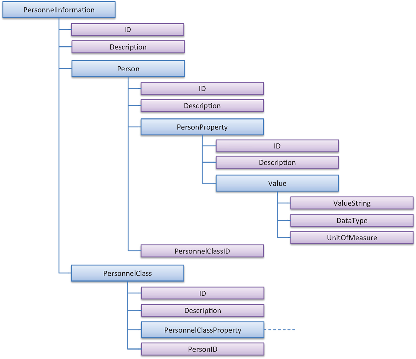
Figure 7. ISA-95 information on personnel.
In practice, if the persons are needed as per their function, it may in fact be sufficient to just list the personnel classes under which the individuals are collected, e.g., “MixerPersonnel” could contain “MixerOperator 1,” “MixerOperator 2,” and “MixerOperator 3.” If we need to distinguish the persons based on their skillset, as in the above case where all mixer operators are not able to operate all mixers, this could be solved by defining classes for each mixer. One operator is namely allowed to be member of several classes. In some cases, very specific properties are needed per operator, for instance, the hourly cost, the “PersonProperty” in the “Person” structures can be used.
Restrictions on Resources: OperationsCapability
After having defined most of the resources necessary for scheduling a production process (equipment, material, and personnel), the OperationsCapability structure defines some important limitations. It can also be used for production stages (ProcessSegments), which may be an important functionality for certain industries, where, for instance, some operations are not allowed to take place during the night due to safety or noise issues. In Figure 8, the main structure of OperationsCapability is shown with a more detailed example on personnel. The main elements for the other resources are exactly the same – only the IDs and ClassIDs must be updated.
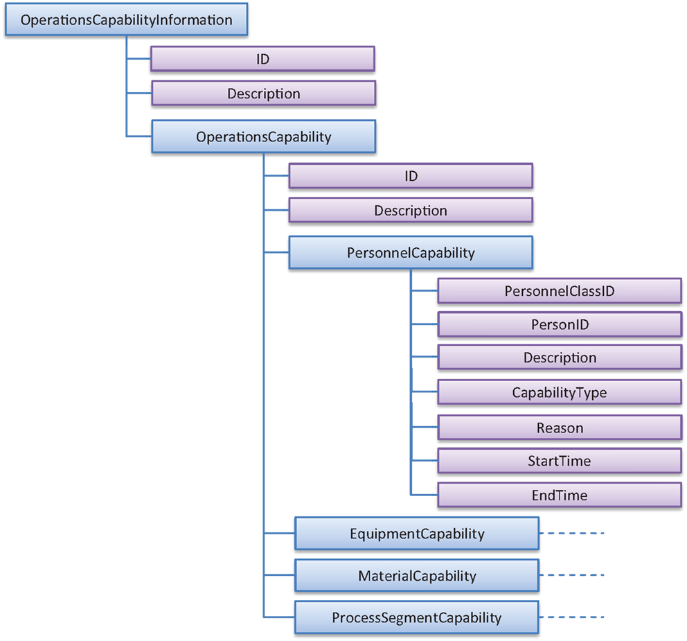
Figure 8. ISA-95 information on capability of resources.
The main entries are which person or personnel class the capability refers to, the capability type (available or unattainable), the reason for this (e.g., vacation), as well as the start- and end-times of the availability or unavailability period. Another capability type “committed” also exist in ISA-95 but here we exclude it. In practice, the OperationsCapability structure makes it easy to specify shifts for personnel and other availability types for equipment and material, as well as for processing steps. One practical note is that it is always better to define either availability or unavailability per equipment, the default assumption being that the opposite is true for the non-specified times.
After having specified these structures, we can now express the following information for the above defined example scheduling problem in ISA-95/B2MML terms:
• Main processing steps of the production plant
• Equipment available for the production
• Material that must be considered in the scheduling
• Personnel needed to be planned by the production scheduling
• Potential limitations in the availability of the above resources
Now when having defined all the items necessary for the production, the focus can be put on the most complex B2MML structure defining the production recipes.
Production Recipes: OperationsDefinition
Production recipes are specified by the ISA-95 structure OperationsDefinition. There is couple of reasons to strictly separate them into their own structure:
• recipes are normally maintained separated in recipe management modules
• owing to the data separation, editing or changing a recipe will be smooth
• a recipe can be repeated multiple times just by referring to a recipe ID
• modification rights can be defined based on the functional role of the people
Production recipes concretely define a product, i.e., describe in detail, which steps need to be performed for producing a given order, which resources are necessary for each of the steps and the durations of the individual steps. The main structural element is OperationsDefinition (see Figure 9), which corresponds to one recipe and is composed of a number of OperationsSegments (processing steps). In the OperationsSegment elements, it is exactly defined which equipment, personnel, or material resources must be brought together simultaneously in order to execute the segment. The recipe can either refer to classes of resources or to the exact instances of the required resources.
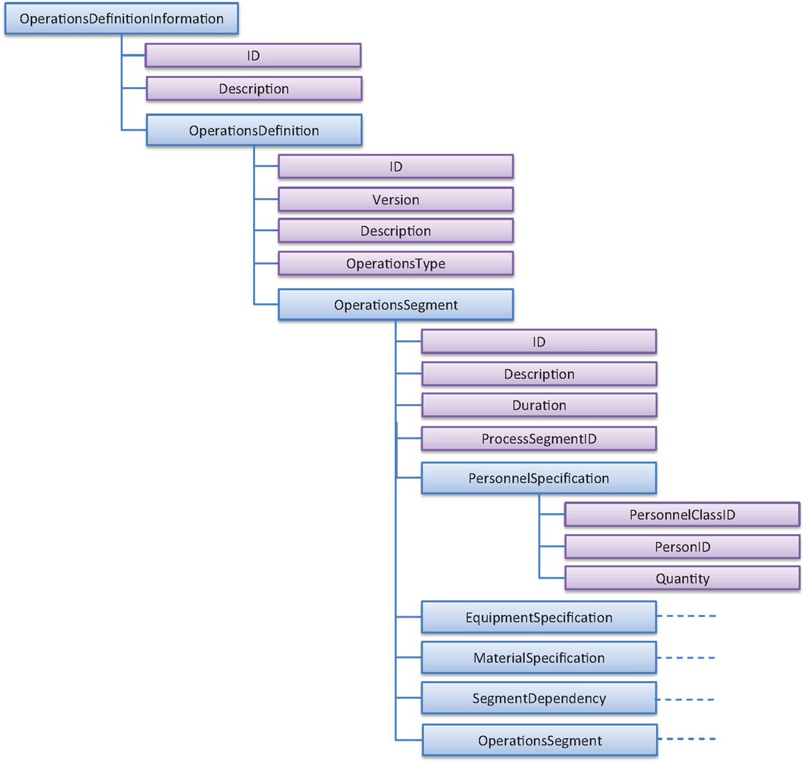
Figure 9. ISA-95 information on production recipes.
In Figure 9, one can see the main fields of an OperationsDefinition. Here, the OperationsType is per default assumed to be “production” but could also be “maintenance” to indicate that the definition corresponds to a maintenance operation, or “inventory” to define, e.g., a filling operation. One sub-tree OperationsSegment is needed for each processing step. It contains entries such as duration, reference to the process segment (in order to inherit some generic restrictions such as the process flow), and the resource specifications, followed by segment dependencies. The recipe either refers to classes of resources, in which case the quantity of resources should be specified – or to the exact instance of a resource required. The segment dependencies provided in an OperationsDefinition are typically recipe-specific and refer always to other process segments.
As these are all input data and should comprise the complete information for the scheduling, one typical case needs to be discussed in more detail. Assume that we had exactly identical production resources to choose from. In this case, it would be possible to specify one unique duration and refer to the various resources through their classes requesting that, e.g., one resource from the class needs to be selected for a considered production step. However, in the case where there are multiple but not identical resources to choose from, equipment-specific data such as duration must be distinguished somehow. A way to handle this could be to introduce EquipmentSpecificationProperty elements under each equipment choice for stating the individual durations. This approach may become complex in cases where several resources depend on the equipment choice. We therefore suggest to deal with this using nested OperationSegments (Figure 10). This means that we must create sub-level operations segments – one for each equipment choice that will have an impact on duration or another resource need. The nested structure is indicated by the number in brackets in Figure 10, where the second level specifies the details that are valid if certain equipment is selected for the production order. The duration element on the first level thus becomes redundant in the input data, which is indicated by the strikethrough text.
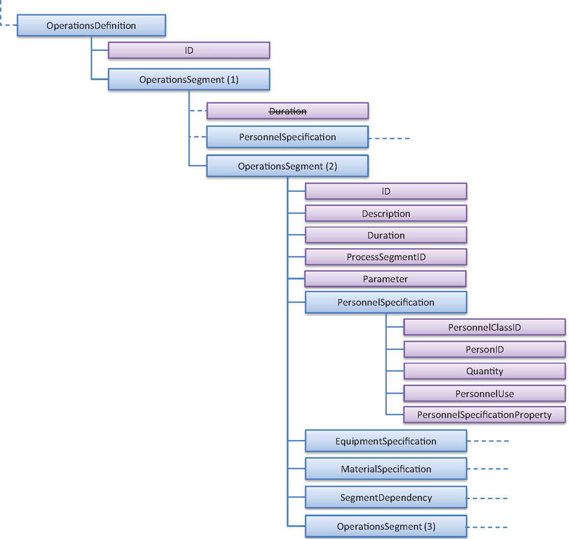
Figure 10. Nested structure of operations segments in production recipes.
In this case, the structures are used as follows. On level 1, OperationsSegment (1), it should be only specified that a number of equipment of a certain equipment class is needed to perform the step. All related definitions for each of the optional pieces of equipment should be provided in OperationsSegment (2), the equipment itself belonging to the EquipmentSpecification section. Other equipment-related resource requirements should be given as in the shown example for personnel specification. Note also that generic parameters can be defined for the segments; however, since the naming convention is not restricted, the parameter IDs, functionality, and logic must be clearly communicated between all connecting systems. A parameter is defined similarly as properties, see for instance, PersonnelProperty in Figure 7. The corresponding XML file for the illustrative example is shown in Supplementary Material.
To summarize, the OperationsDefinition structure collects all resources together and defines how these should be used together at each production step in order to produce a production order. Due to the fact that most of the resource information is maintained separately by, for instance, other departments or software, the approach with separated data structures is very well motivated. The operations definition can naturally be expanded and used in a flexible way. For instance, a third level of OperationsSegment could be defined to display some subtasks but in this particular case, the information would not be used for optimization. However, we leave this topic, as well as other specific detailed cases, out of the discussion here and focus on the core information that a scheduling optimizer needs to know to successfully perform its task.
Production Order Requests: OperationsSchedule
The B2MML-element OperationsSchedule (Figure 11) can be seen having two main functionalities or roles. It is a container for the production order requests specifying what needs to be scheduled and after the scheduling task it feeds back the optimized schedule. The latter role is the original one fully supported by the ISA-95 standard. The upper element of OperationsSchedule may contain, apart from the ID, also a description, release date of the schedule (“zero time”) in the StartTime field and after the scheduling the make span in the EndTime field. These are namely the only time-related fields defined by the standard. In the ideal case, the input file is a list of operations requests that contain the order IDs, a reference to the recipe (OperationsDefinitionID), operations type (if not production), release and due dates for the order, and a priority for each order. Based on this information, the production schedule can be fully created. Other necessary parameters could be embedded into a SegmentRequirement element and if certain values must be retrieved from the process during the execution, the placeholder for this information is SegmentResponse, which in fact defines the data that need to be retrieved from during production from the shop floor, i.e., expected segment response.
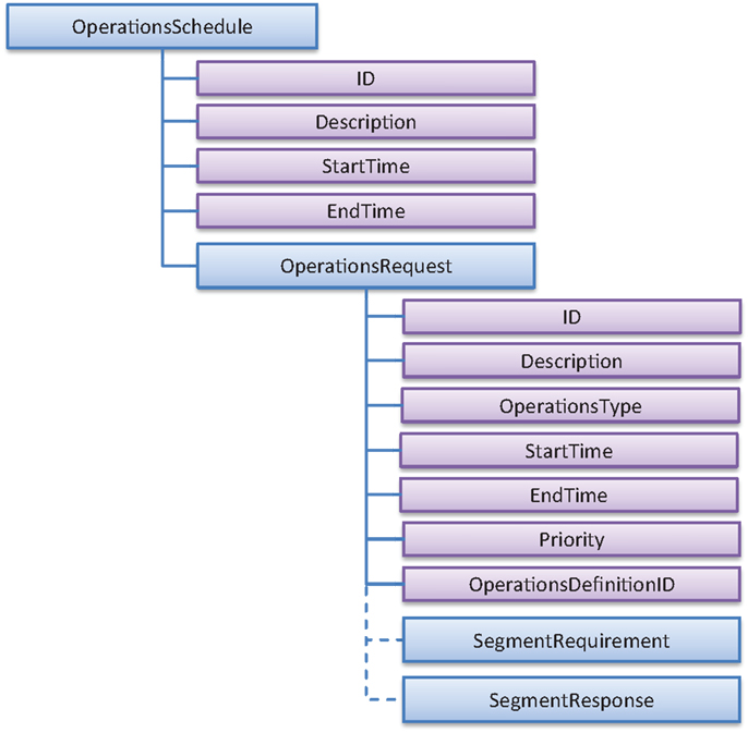
Figure 11. ISA-95 information for Operations Schedule (input to scheduler).
After the scheduling task has been completed, the resulting schedule should be filled into the underlying segment requirement fields containing exactly the resource and timing information of operations determined by the scheduler. This information should be complete in order to enable a proper dispatching of the operations requests onto production (shop floor). The most important information for the main element OperationsSchedule is the end time of the schedule, corresponding to the make span. The remaining information falls into the individual operations requests and their segment requirements. Unfortunately, the standardized namings of ISA-95 do not cover all needed terms, which mean that there are two options: define them as parameters or use the closest match. We have selected the latter option in order to maximize the benefits of using a standard and its defined XML schemas. All other relevant pieces of information are basically packed into the segment requirements. For each production step (SegmentRequirement), the start time (EarliestStartTime), end time (LatestEndTime), and duration have now been defined by the scheduler. In the same manner, the personnel-, equipment-, and material requirements should now contain only those resources that have actually been planned for the operation, including the consumption or production of the planned resources. In Figure 12, the main elements of the resulting structure are shown and, as before, we highlight that the resulting XML file should contain one OperationsRequest element per order and within these one SegmentRequirement for each productions step defined for the order.
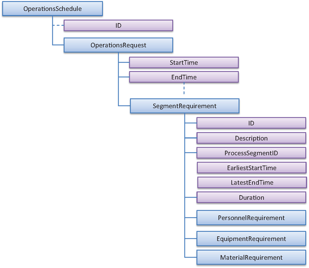
Figure 12. ISA-95 information for Operations Schedule (output from scheduler).
By using the ISA-95 standard in the described way, all important data for a typical scheduling problem can be covered by the B2MML structures in a generic way. The structures also remain the same, independent of which industry we refer to. Furthermore, all tag-names and locations shown in the figures of this paper are clearly specified by the XML schemas and this makes it easy to find the location of the information of interest. A complete set of the input information for the defined example problem can be found in Supplementary Material.
Connection to the Control-Level: OperationsPerformance
After the scheduling task has been completed and the resulting short-term production plan submitted or dispatched to the production, it is for an industrial implementation very important to also be able to follow-up and track the production. All values related to timing, e.g., durations are only best estimates known during the planning and cannot take into account natural deviations or disturbances in the process that may occur at any time. In order to have the means to systematically track the production and communicate the actual situation at the shop floor back to the scheduler, there exists another B2MML structure called OperationsPerformance, which hosts another structure OperationsResponse. The latter structure contains the elements for providing information on delays or earlier execution, actual consumption of resources, etc. An example of the information is shown in Figure 13.
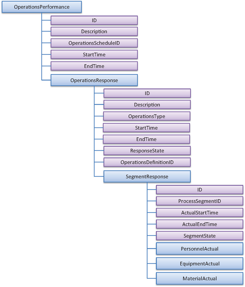
Figure 13. ISA-95 information for OperationsResponse (feedback from the process).
The main information is located at the segment responses, where the actual start- and end-times of each processing stage is given, the state of the segment (ready, running, completed, aborted) and the actual usage and consumption of resources. By replacing the assumed (planned) values with the information from the OperationsResponse and fixing them, a rescheduling can be done that builds upon the actual production situation without any other mechanisms needed. Further details can be found in the ISA-95 documentation.
Now all main elements of the ISA-95 implementation (B2MML) that are necessary for describing a typical scheduling problem have been explained. Also, some adaptations on how to use the standard have been developed, mainly following the provided B2MML structure (rectangles in Figures), but also defining allowed properties and parameters that are necessary for hosting the information for scheduling. The next natural step is to implement them on the earlier defined illustrative test case. The resulting XML files for the considered case have been simplified such that only relevant information is shown in order to shorten the files. They can be found in Supplementary Material. For instance, in the examples where the considered material has been given a unit of measure at the material definition, this is not anymore repeated at the operations definition level when a quantity is given. All other details and additional options of how to use ISA-95 and B2MML can be freely downloaded from the ISA-95 web page1.
Systems Overview on Applying the ANSI/ISA-95 Standard
Even if the data and problem information is collected correctly and in a standardized format, this does not do the entire job. The data also need to be part of a system; it must be understood as well as communicated between different components and applications. The ISA-95/B2MML format provides several benefits, for instance, by specifying the exact structure where to find certain type of information and by enabling the use of XML-support libraries for major modern programing languages (C#, java). This makes it possible to read and write the entire set of XML files within a few lines of code using the schema files (XSD) that describe the XML contents and rules. Also validation of the XML-file syntax can be easily done in an automated manner. This helps creating an infrastructure that can efficiently load, manipulate, and save scheduling-related information. Sharing the data between different applications and functions becomes easy if there is, for instance, a common database that utilizes the ANSI/ISA-95 standard. Other possible ways to ensure access to the B2MML structures is via simple filesharing (local drive) or more preferably through to use of web services, which enables communication via intra- or internet, i.e., the geographic location of individual system components is completely flexible. Figure 14 shows an example reflecting the structures discussed in this paper. Different functions ranging from ERP (planning) to control must share the information in order to ensure that all important data are available where needed.
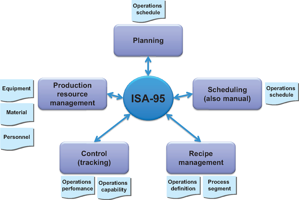
Figure 14. ISA-95 data base for easy information sharing.
A common database allows a natural distribution of responsibilities between several applications. This is a fact that speaks for the ISA-95 standard since many production systems already today provide a native ISA-95 support. Having already, for instance, the resource and recipe management applications connected to the ISA-95 database makes it natural to plug-in a new component such as scheduling.
Nevertheless, even if this solves the problem of data sharing, it does not remove the work of matching the data with a specific algorithm. For instance, how to account for variable equipment choices or on the dependencies between subsequent processing steps is highly different if a heuristic or mathematical programing method is being applied. An example for two MILP-based methods is shown in Figure 15. The example shows how to build constraints for a dependency between two stages (reaction and packaging). The upper right rectangle shows a continuous-time scheduling approach formulating two constraints between the starting time variable of the packing and finishing time variable of the reaction. The relationship between B2MML and mathematics is illustrated by rectangles and circles. The lower right rectangles display an equivalent discrete-time approach (below) with a time grid of one minute in order to make the example more illustrative. Here, we link the two variables together such that the packing start variable must be true exactly 15–60 min after the reaction variable indicates the end of the reaction step. Note that, the processing time is an offset on the left hand side and that there exists a constraint forcing both variables to be equal to one exactly at one time point.
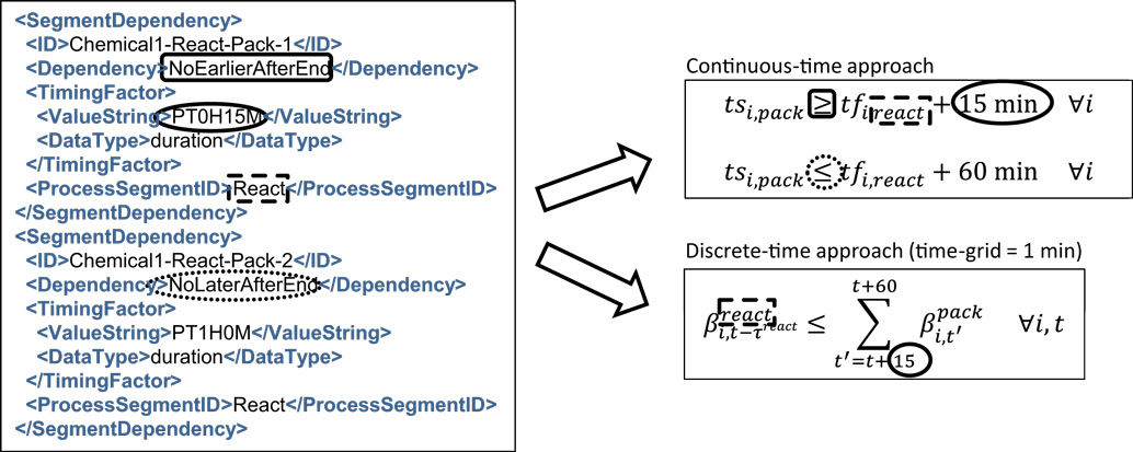
Figure 15. Translating the ISA-95 information into a model.
In both of the methods, one can clearly see that the time-relation defined by SegmentDependency provides a lower and upper bound to the timing decisions of the two operations. These constraints can be generated automatically once the main principles have been implemented in a re-usable way. In a way, this shows that the information in the B2MML files can provide more than just data. Similar logic can be used for heuristic approaches as well, but there it is often beneficial to copy the B2MML data into a more efficient, tailor-made data structure to speed up the heuristic algorithm.
Conclusion and Future Research
The increasing utilization of scheduling solutions, especially in industrial process optimization, necessitates the development of a common interface for data exchange. The benefits of such an interface are numerous: inside an industrial application domain, it simplifies the handling by controlling the data flow between MES and scheduling algorithms. It also allows and supports the development of more holistic solution frameworks by easily exposing the methods to a multitude of various problem instances. Such frameworks would greatly reduce the efforts necessary for introducing a scheduling approach to a given application. Up to now, most scheduling solutions are very application-specific and the synergies between different applications are low. This prohibits the deployment of scheduling in some areas due to the involved high development costs. Finally, a common interface can foster further progress in the field by supporting the communication between academia and industry, especially in efficiently exchanging problem instances and testing new approaches on real industrial problems.
However, many obstacles lie on the path to a general scheduling interface. The interface must be powerful enough to express a wide range of problem classes, yet simple enough to be easily understandable. Additionally, it should work independently from a given hardware setup. To be truly successful, it also has to be widely accepted both in industry and academia.
In this paper, we have investigated and proposed the use of ANSI/ISA-95 standard as such an interface. Using a case-study stemming from a batch process in chemical industry, we have modeled a scheduling problem in ISA-95 terms. We have also filled the remaining degrees of freedom in the semantics and shown how the batch process could be modeled in ISA-95/B2MML.
It turns out that the problem can be quite well modeled in ISA-95 with few efforts, maintaining good readability and incorporating all desired features. Furthermore, the model is expandable in case additional features occur later at the implementation phase. As an approved international standard, ANSI/ISA-95 is already widespread in the industry and seen as a neutral platform between vendors. Through B2MML, an XML-based ISA-95 implementation is available that makes it easy to share given instances across platforms, systems, or companies.
A natural next step in research is to develop algorithmic libraries and methods that accept ISA-95-based instances as an input. This could pave the way toward a much sought-after holistic scheduling solver that analyzes the problem and selects or recommends the most suitable method for solving it. Having a solver that can be used by modelers without algorithmic knowledge would mean a tremendous boost in the industrial applicability of scheduling solutions.
Finally, a promising next step is the development of a complete scheduling framework, which is modular enabling also flexible user interaction, can host several algorithms and where the data exchange is only done through ISA-95. Having a data storage, communication with MES/CPM or other external systems, graphical visualization component, and algorithms coordinated solely via the ISA-95 standard would result in a solution that is perfectly integrable and, at the same time, holistic, as well as easily customizable for industry-specific needs. This is what industry longs for.
Conflict of Interest Statement
The authors declare that the research was conducted in the absence of any commercial or financial relationships that could be construed as a potential conflict of interest.
Supplementary Material
The Supplementary Material for this article can be found online at http://www.frontiersin.org/Journal/10.3389/fenrg.2014.00044/abstract
Footnote
References
ANSI/ISA-95.00.03-2005. (2005). Enterprise-Control System Integration, Part 3: Activity Models of Manufacturing Operations Management. Research Triangle Park, NC: ISA–The Instrumentation, Systems, and Automation Society.
Chu, Y., and You, F. (2012). Integration of scheduling and control with online closed-loop implementation: fast computational strategy and large-scale global optimization algorithm. Comput. Chem. Eng. 47, 248–268. doi: 10.1016/j.compchemeng.2012.06.035
Engell, S., and Harjunkoski, I. (2012). Optimal operation: scheduling, advanced control and their integration. Comput. Chem. Eng. 47, 121–133. doi:10.1016/j.compchemeng.2012.06.039
Framinan, J. M., and Ruiz, R. (2012). Guidelines for the deployment and implementation of manufacturing scheduling systems. Int. J. Prod. Res. 50, 1799–1812. doi:10.1080/00207543.2011.564670
Grossmann, I. E. (2005). Enterprise-wide optimization: a new frontier in process systems engineering. AIChE J. 51, 1846–1857. doi:10.1002/aic.10617
Harjunkoski, I. (2012). Planning and scheduling as a part of a control system – implementation aspects. Comput. Chem. Eng. 31, 1110–1114. doi:10.1016/B978-0-444-59506-5.50053-5
Harjunkoski, I., Bauer, M., and Horch, A. (2013). Scheduling Integration Using an ISA-95 Application in a Steel Plant. Chapter for ISA-95 Best Practices Book 3.0. Research Triangle Park, NC: The MOM Chronicles.
Harjunkoski, I., Maravelias, C. T., Bongers, P., Castro, P. M., Engell, S., Grossmann, I. E., et al. (2014). Scope for industrial applications of production scheduling models and solution methods. Comput. Chem. Eng. 62, 161–193. doi:10.1016/j.compchemeng.2013.12.001
Henning, G. P. (2009). Production scheduling in the process industries: current trends, emerging challenges and opportunities. Comput. Aided Chem. Eng. 27, 23–28. doi:10.1016/S1570-7946(09)70224-X
Muñoz, E., Capón-García, E., Laínez, J. M., Espuña, A., and Puigjaner, L. (2013). Integration of enterprise levels based on an ontological framework. Chem. Eng. Res. Des. 91, 1542–1556. doi:10.1016/j.cherd.2013.04.015
Muñoz, E., Capón-García, E., Laínez-Aguirre, J. M., Espuña, A., and Puigjaner, L. (2014). Using mathematical knowledge management to support integrated decision-making in the enterprise. Comput. Chem. Eng. 66, 139–150. doi:10.1016/j.compchemeng.2014.02.026
Keywords: scheduling, industrial standards, collaboration, integration, re-usability
Citation: Harjunkoski I and Bauer R (2014) Sharing data for production scheduling using the ISA-95 standard. Front. Energy Res. 2:44. doi: 10.3389/fenrg.2014.00044
Received: 29 June 2014; Accepted: 01 October 2014;
Published online: 21 October 2014.
Edited by:
Gurkan Sin, Technical University of Denmark, DenmarkReviewed by:
Pradeep Suresh, The Dow Chemical Company, USAFranjo Cecelja, University of Surrey, UK
Arun Giridhar, Engineering Research Center for Structured Organic Particulate Systems, USA
Copyright: © 2014 Harjunkoski and Bauer. This is an open-access article distributed under the terms of the Creative Commons Attribution License (CC BY). The use, distribution or reproduction in other forums is permitted, provided the original author(s) or licensor are credited and that the original publication in this journal is cited, in accordance with accepted academic practice. No use, distribution or reproduction is permitted which does not comply with these terms.
*Correspondence: Iiro Harjunkoski, ABB Corporate Research, Industrial Software and Applications, Wallstadter Str. 59, Ladenburg 68526, Germany e-mail:aWlyby5oYXJqdW5rb3NraUBkZS5hYmIuY29t