 Alexander Beez
 Kevin Schiemann3
 Norbert H. Menzler
- 1Christian Doppler Laboratory for Interfaces in Metal-Supported Electrochemical Energy Converters, Jülich, Germany
- 2Forschungszentrum Jülich, Institute of Energy and Climate Research, IEK-1: Materials Synthesis and Processing, Jülich, Germany
- 3Forschungszentrum Jülich, Institute of Energy and Climate Research, IEK-9: Fundamental Electrochemistry, Jülich, Germany
A straightforward method for accelerated testing of Cr poisoning phenomena on mixed ionic and electronic conducting (MIEC) Solid Oxide Cell (SOC) air electrode materials was developed. Cr2O3-powder is mixed with an organic matrix and screen printed onto anode-supported button cells with (La,Sr)(Co,Fe)O3−δ (LSCF) cathode. Then, a thermal treatment was conducted to achieve the formation of a well-defined amount of SrCrO4 on the cathode surface within only a few hours. For the proof of concept, single cell measurements were done to investigate the influence of this new kind of Cr deposition. As reference, a cell poisoned via gas phase diffusion and a cell without any Cr contamination were characterized in the same manner. According to the impedance data, the polarization resistance for both cells, which were contaminated with Cr species, increased. The expected relationship between deposited amount of Cr and increase of polarization resistance was found. ICP-OES analysis proves the high reproducibility of the method as the Cr content is only a function of the Cr paste composition and almost independent of external poisoning conditions. Due to its scalability and reproducibility, this method is proposed to be a new tool for screening of cathode materials and the investigation of different stages of Cr poisoning prior to more sophisticated and time consuming investigations like stack tests.
Introduction
Cr poisoning is one of the major issues limiting the lifetime of solid oxide fuel cells (SOFC) and electrolysis cells (SOEC). Gaseous hexavalent Cr species can evaporate from the metallic interconnect or balance-of-plant components and interact with the ceramic air electrode thereby leading to a loss of performance (Menzler et al., 2011). The preferred cathode materials for SOFC are mainly mixed ionic and electronic conducting (MIEC) perovskites like (La,Sr)(Co,Fe)O3−δ (LSCF) and (La,Sr)CoO3−δ (LSC). These materials deliver a high electrochemical performance, but due to the segregation of the Sr from the A-site of the perovskite lattice to the surface (Finsterbusch et al., 2012; Rupp et al., 2015), they are prone to reacting with volatile Cr species (Simner et al., 2006). According to the nucleation theory (Jiang and Zhen, 2008), the degradation mechanism is believed to be driven by a kinetically fast chemical reaction between the segregated Sr species and the volatile Cr species. As a result, SrCrO4 crystals are mainly localized on the surface of the cathode layer, which is in good agreement with many experimental findings (Konysheva, 2014; Wang et al., 2014; Zhao et al., 2014). In contrast, composite cathodes consisting of purely electronic conducting perovskite (La,Sr)MnO3−δ (LSM) and ionic conducting yttrium-stabilized zirconia (8YSZ) show a degradation behavior were the Cr containing species, a (Cr,Mn)-spinel phase, is located at the cathode/electrolyte interface (Badwal et al., 1997; Jiang et al., 2000). Due to their lower electrochemical performance especially at lower temperature (~700°C) compared to single phase cathodes like LSCF and LSC, those LSM/8YSZ composites were less attractive for use in intermediate temperature SOFC in past decade (Mai et al., 2005). Therefore this study focuses only on mixed conducting cathode materials as they represent the current state-of-the-art for SOFC and SOEC.
Cr related degradation phenomena are often investigated via single cell or half-cell measurements, which represent the electrochemical system on a small scale. Many experimental setups implement a metallic Cr source into the cathode gas feed (Kornely et al., 2013; Konysheva, 2014; Wei et al., 2015). However, evaporation from such a metal source is a function of many parameters, such as the available surface area, Cr content, temperature, flow regime, and gas humidity (Hilpert, 1996; Trebbels et al., 2009). The comparison of different samples is especially challenging if the poisoning conditions cannot be controlled sufficiently for all experiments. In addition, it is time consuming to achieve the same level of Cr deposition, which can be found on the cathode after long-term stack operation.
In this work, we present the new and straightforward approach of solid state poisoning to overcome the aforementioned restrictions. Solid state poisoning has the potential to be highly reproducible and scalable in terms of Cr content deposited on a sample and is especially suitable for porous cathodes with applied microstructure. Our method enables to mimic the increasing amount of Cr deposited on a cell during long-term stack operation within a few hours and to benchmark novel cathode materials regarding their affinity of Cr poisoning. Therefore, it can become a versatile tool for future development of high performance SOFC cathode materials, whose function is based on mixed ionic and electronic conduction.
Experimental
Paste Preparation
Cr2O3 powder was mixed with an organic matrix consisting of 6 wt-% ethyl cellulose (Sigma Aldrich) and 94 wt-% terpineol (DuPont). The components were first stirred roughly with a spatula by hand and then mixed in a planetary centrifugal Thinky™ Mixer for 6 min (3 × 2 min to avoid heating of the vessel) at 1,000 rpm. The resulting paste appears to be homogeneous, without macroscopic agglomerates. The amount of Cr2O3 powder in the paste was calculated considering the wet layer thickness of the screen used for the screen printing process. It was targeted to achieve a Cr deposition, which is comparable to average Cr contents found in LSCF cathodes after several thousand hours of stack operation with JÜLICH specific stack design (~100–200 μg cm−2) (Menzler et al., 2011; Beez et al., 2017). The Cr content of the paste was adjusted to 6.2 wt.-% (equals 0.1 g Cr2O3 per 1 g organic matrix) with the aim to achieve a Cr deposition of ~100 μg cm−2. In order to avoid infiltration of the paste into the cathode layer, Cr2O3 powder with a d50 of 0.99 μm (Fluka) was chosen, as its mean particle size is bigger than the average pore diameter of JÜLICH standard cathodes.
Solid State and Gas Phase Poisoning
Commercial anode–supported solid oxide button cells with a diameter of 20 mm supplied by CeramTec (Germany) were used for this work. They consist of a NiO/8YSZ anode support, a NiO/8YSZ anode, an 8YSZ electrolyte, and a screen printed GDC diffusion barrier layer. The 40 μm thick (La0.58Sr0.40)(Co0.20Fe0.80)O3−δ cathode was applied by screen printing as well starting from an in-house produced LSCF powder (d50 = 0.8 μm). The cathode has a diameter of 10 mm. Sintering was conducted at 1,080°C under air atmosphere for 3 h. The anode was activated under H2 at 950°C during the startup of the cell in the single cell measurement. Two different techniques have been used to poison the samples.
Solid State Poisoning: The Cr paste is screen printed on a cell using a screen with a wet layer thickness of 40 μm. The diameter of the printed area was set to 9 mm, allowing for some excess space in case the Cr paste spread due to its low viscosity. After a drying step at 70°C for 1 h, the solid state reaction (1) was triggered by thermal treatment at 750°C under air atmosphere.
Preliminary tests revealed that at least 12 h are necessary to ensure an almost complete reaction of the screen printed Cr2O3 with the Sr species from the cathode. The complete course of the reaction was verified by SEM/EDX analysis, but was also indicated by a color shift of the sample from the green of the Cr2O3 paste to a dark gray of the reaction products. Due to the temperature used for solid state poisoning, Cr2O3 will also partly evaporate and react with air humidity to form CrO2(OH)2 as shown in (2) (Hilpert, 1996), thereby giving rise to a secondary poisoning mechanism via gas phase diffusion.
To ensure a complete reaction of the deposited Cr2O3 XRD measurement has been conducted (Bruker D4).
Gas Phase Poisoning: Gas phase poisoning was used to prepare a cell more closely mimicking the situation in a real SOFC stack, where solid state reaction does not occur. A cell was placed under an Al2O3 frame (height: 2 mm) which was covered by high Cr-containing ferritic steel resulting in a closed gas volume between the Cr source and the sample surface. The interconnect steel ITM (= Intermediate Temperature Metal from Plansee SE, Austria) was used as a Cr source. This steel forms a Cr2O3 protection layer under oxidizing conditions (Trebbels et al., 2009). The experimental setup of cell, frame and Cr source was kept at 750°C for 72 h. Cr poisoning at the sample surface takes places according the Equation (3).
An elongated exposure time was used in this case to ensure the deposition of a sufficient amount of Cr on the sample, as the volume of the furnace was quite large compared to the sample size.
Table 1 summarizes the three cells used for electrochemical characterization and the applied technique used for poisoning.
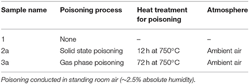
Table 1. Overview of the samples used for electrochemical characterization.
The amount of Cr in the samples was measured using a wet chemical method, which is described in more detail in the literature (Menzler et al., 2011).
Electrochemical Characterization
A 4-probe setup was used for electrochemical characterization, in which cathode and anode were set as working/sense electrode (WE/S) and counter/reference electrode (CE/RE), respectively. In order to contact both electrodes individually, Pt- (cathode) and Pt/Ni- (anode) current collectors were utilized. A gold gasket with a thickness of 0.3 mm was used to separate the anode and the cathode compartment. Ultrapure hydrogen (9 Nl h−1) on the anode side and compressed air (14 Nl h−1) on the cathode side were used as feed gases. After a button cell was installed in the setup, it was heated up to 900°C and the anode was activated. By turning on the gas supply, the NiO was stepwise reduced to metallic Ni. Starting at 900°C, an electrochemical impedance measurement was conducted at a constant potential of 0.7 V within a frequency range of 110 kHz−1 mHz and with an excitation amplitude of 20 mA cm−2. After completion of the measurement at the selected temperature, the cell-temperature was lowered by 50 K at a cooling rate of 1 K min−1. The impedance measurement and cooling step were repeated until a cell-temperature of 650°C was reached. In this work, only the impedance spectra recorded at 700°C will be used for discussion. An in-depth analysis of the impedance data and the related electrochemical processes will be presented elsewhere.
Results
Wet Chemical Analysis
For chemical analysis of the Cr content, the cathode layer with the Cr-containing reaction products on top was dissolved in perchloric acid and the Cr content of the solution was measured by inductively coupled plasma-optical impedance spectroscopy (ICP-OES). For both poisoning methods three cells have been characterized. Table 2 summarizes the results of the wet chemical etching.
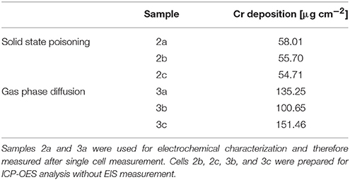
Table 2. Amount of Cr per cm−2 cell determined by ICP-OES.
The ICP-OES analysis proved the high reproducibility of the solid state poisoning technique. For this method, the values scatter by approximately 7%, while for the poisoning via gas phase, values in the range of 100–150 μg cm−1 were measured. The results of the ICP analysis also show that the Cr deposition achieved via solid phase poisoning did not match the target of around 100 μg cm−2.
To verify a complete reaction of the Cr2O3 with the Sr from the cathode, XRD measurement has been conducted.
Figure 1—shows the XRD pattern of the cell 2a after the thermal treatment at 750°C for 12 h.
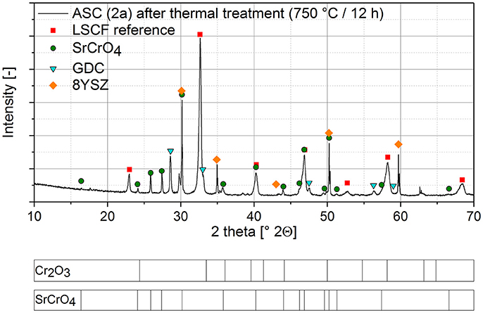
Figure 1. XRD analysis of a single cell after Cr poisoning via solid phase poisoning and thermal treatment for 12 h at 750°C.
In the XRD-pattern, SrCrO4 became the main Cr-containing phase while there is no indication of residual Cr2O3. Considering the XRD detection limit a complete reaction of the Cr2O3 is supposed. The presence of the GDC and 8YSZ phases in the pattern accounts to the measuring device which scans a larger diameter than cathode diameter.
Microstructural Analysis
Figure 2 shows the top views (left) and the fracture surfaces (right) of the three cells after the single cell measurement.
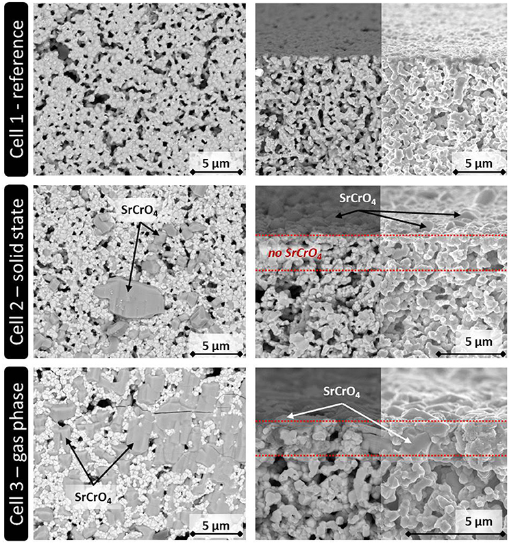
Figure 2. SEM analysis of the three ASC button cells used for the electrochemical characterization. (Left) Top view. (Right) Fracture surface of the upper part of the cathode layer (backscattered electron detector/In-lens detector).
In the case of Cell 1, the LSCF cathode shows larger pores in the microstructure, which might be residuals from the processing, like small drying cracks, which remained after the sintering and were representative for all cathodes considered in this study. Those pores might allow small Cr2O3 particles to enter the cathode layer during screen printing. However, no indication for such an infiltration was found by SEM analysis of Cell 2. As expected, the Cr-containing crystals are randomly spread solely on the surface of the cathode of cell 2, indicating that they derived from the screen printed Cr2O3 particles.
For Cell 3, the gas phase deposition led to the formation of SrCrO4, which almost homogenously covers the complete sample surface. The fracture surface of Cell 3 shows that the reaction products between volatile Cr and Sr from the LSCF cathode can in addition penetrate the first 2–3 μm of the cathode layer, but it is expected that this little infiltration does not change the cell degradation significantly if compared to Cell 2. For both cells, there is no indication that Cr species reached the bulk of the LSCF cathode in Cell 2 or 3. This indicates that the Cr species remained localized at the top of the cathode layer during cell operation as intended. From this result, it was concluded that the solid phase poisoning led to the same kind of Cr poisoning as reported in the literature for LSCF cathodes independent if they are used in real stack tests or single cell measurements (Menzler et al., 2011; Konysheva, 2014).
Electrochemical Impedance Measurements
Degradation of electrochemical performance caused by an interaction with a solid or gaseous Cr species was studied by electrochemical impedance spectroscopy.
Figure 3 shows the impedance plots at 700°C.
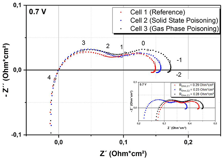
Figure 3. Comparison of impedance data of the cells taken at 0.7 V and 700°C. Frequencies (in Hz) used for impedance spectroscopy are given on a logarithmic scale. Inset: Original data without subtraction of the ohmic resistance.
For better comparability, the impedance spectrum for each sample has been shifted by subtracting the ohmic resistance. The ohmic resistances for the cells were 0.29, 0.23, and 0.28 Ohm cm2 for Cell 1, 2, and 3, respectively. The ohmic resistance is often attributed to physical parameters such as the thickness of the electrolyte or the contact between the cell and the current collector. As we could not find any significant microstructural difference of the three cells, we suppose that the difference of ohmic resistance is caused by contact issues of the experimental setup. The comparison of the three cells shows an increase of the polarization resistance with increasing Cr content, especially in the low frequency range. This is in good agreement with literature, in which cathode-related processes are also assigned to this part of the frequency range (Konysheva, 2014; Ni et al., 2016). Most importantly, the data show that the Cr treatment seems to have a similar effect on the impedance spectra regardless of the poisoning technique. This indicates that the solid state poisoning route is a promising alternative to the gas phase poisoning.
Discussion
The results achieved so far are quite promising in terms of comparability and reproducibility. For both applied poisoning techniques, reaction products like SrCrO4 crystals are mainly located on top of the cathode layers, showing only a small penetration depth of 2–3 μm into the LSCF cathode in the case of gas phase deposition. SEM analysis also revealed that the Cr poisoning applied by solid state reaction remained localized to the screen printed area, even after heat treatment and single cell measurement. The difference between the aspired Cr deposition (around 100 μg cm−2) and the measured amount (~50 μg cm−2) has two possible explanations. (i) The paste composition has an influence on the wet layer thickness achieved after screen printing. The organic matrix used for the Cr paste was derived from our cathode paste and is optimized for solid content of up to 40 wt.-%. However, the Cr paste has a solid content of only ~10 wt.-%. As a result the paste is rather sticky. During the screen printing the paste could be partly removed from the sample when the screen retracts after the squeegee has passed it. Therefore, optimization of the paste composition and screen printing process is required to establish the solid poisoning approach. (ii) It is supposed that the burn-off of the organic binder, which was conducted at 750°C in ambient air, triggers an unexpected loss of Cr by evaporation of Cr species like CrO3 and/or CrO2(OH)2. Such evaporation could not be completely avoided at temperatures above 600°C (Hilpert, 1996). In addition the Cr2O3 particles possess a large surface area which also favors evaporation as competing reaction to (1). This issue could be resolved by adding a dwell time at lower temperature (e. g., 300°C) where the evaporation of Cr2O3 is negligible before triggering reaction (1) at higher temperature. In sum, an adjustment of the Cr content of the paste and an improvement of the screen printing process are required to better adjust the Cr content in the case of solid state poisoning.
Both poisoning methods seem to cause a similar change in the impedance spectra, even though the amount of Cr deposited via gas phase diffusion did not match the poisoning achieved via solid state poisoning. That both samples show a similar behavior in the impedance measurements is in good agreement with the chemical degradation behavior of LSCF cathodes reported in literature (Hilpert, 1996; Fergus, 2007; Menzler et al., 2011). It seems likely that the Cr degradation on both samples triggered a limitation of the gas transport and/or surface exchange by hindering oxygen from entering the porous cathode layer. The electrochemically active sites, which are located close to the LSCF/GDC barrier, remained intact and did not suffer from the specific kinds of Cr poisoning treatment done in this study. Another interesting fact is that even the severe SrCrO4 deposition on Cell 3 did not lead to contact problems with the platinum mesh used during the electrochemical characterization, even though the total conductivity of SrCrO4 is approximately 6 orders of magnitude lower than that of LSCF at 800°C (Liu and Konysheva, 2014).
As this method was developed for use as accelerated testing, the comparison to recent stack results is of high interest. The amount of Cr deposited on the cathode strongly depends on the Cr protection coating applied to the interconnect and the operating temperature (Beez et al., 2017). For stacks with less efficient Cr protection coatings (e.g., porous coatings applied by wet powder spraying), which were operated for up to 17.000 h, we measured a Cr content in the range of 100–200 μg cm−2 on the stack level (Menzler et al., 2011; Menzler and Batfalsky, 2012; Beez et al., 2017). So far a non-linear correlation between the amount of Cr deposited on an LSCF cathode and the operation time of a stack was measured (Menzler and Batfalsky, 2012) and a Cr content in the range of 200 μg cm−2 is the highest value reached for JÜLICH ASC stacks so far. Solid state poisoning by screen printing of Cr2O3 powder enables to deposit the equivalent amount of Cr in <1 day, including preparation of the paste, screen printing and thermal treatment. However, to ensure a complete reaction of the Cr2O3 in the paste with the Sr from the cathode, we propose to increase time of the thermal treatment and Cr content of the paste. In addition to the time-saving aspect, this method shows much higher reproducibility compared to poisoning via gas phase diffusion and is therefore also an inexpensive alternative to more sophisticated methods, such as depositing a Cr species via physical vapor deposition.
The results presented so far are a preliminary but highly promising approach, and leave some room for improvement and further experiments. First, a modification of the paste composition could be helpful to adjust behavior of the paste during screen printing and thus the Cr deposition and distribution. So far the Cr2O3 powder is preferentially localized at the outer areas of the sample. This tendency was already observed during the SEM analysis of Cell 2. With an optimized paste, a more homogeneous distribution of the Cr2O3 powder on the cell is expected.
A major limitation of this method is that it is only applicable for cathode materials which exhibit a degradation behavior driven by a chemical reaction in which the Cr species are mostly located on top of the cathode layer. This method would not be suitable for an LSM/8YSZ composite cathode, as the Cr-containing phase is normally located at the interface between the cathode layer and the electrolyte (Taniguchi et al., 1995; Matsuzaki and Yasuda, 2001). For these cathodes, a method such as that proposed by Ni et al. might be an alternative (Ni et al., 2016). This method utilizes a Cr-nitrate solution to infiltrate the cathode, allowing a direct interaction between the electrochemically active sites of the cathode and the Cr species.
Conclusion
In this work, a straightforward experimental method was described which enables reproducible Cr poisoning of SOCs within a few hours. First, a paste containing Cr2O3 powder and an organic binder system was screen printed onto ASC button cells. After a heat treatment to trigger the poisoning reaction, electrochemical impedance measurements were conducted and the results were compared to those of a Cr free reference cell and an identical cell which was poisoned via gas phase diffusion. Even though the amount of the Cr-containing deposits differed between the two poisoning methods, the influence on the impedance behavior was found to be similar, as the polarization resistance of both samples increased significantly with respect to that of the Cr-free reference. This is attributed to the nature of the Cr poisoning of LSCF cathodes, which is dominated by or restricted to a chemical reaction and results in the formation of SrCrO4 crystals on the surface of the cathode layer. Therefore, the effect characterized by impedance spectroscopy is likely triggered by the partial blocking of the pores of the LSCF cathode with SrCrO4 crystals which then influences the electrochemical performance of the cells. This work is a first approach to accelerate and standardize Cr poisoning of mixed conducting cathodes, but there is still room for further optimization. Up to now, composition of the paste and screen printing parameters paste as well as the temperature program for the poisoning were not optimized leading to a noticeable difference between the predicted and the actual amount of Cr deposited on the sample surface.
Despite that, this work proofs the potential of this method to provide insight into the long-term degradation behavior of MIEC cathodes, such as LSCF and LSC. The method allows for the preparation of samples with a predefined Cr content by adjusting the Cr content of the organic paste, providing the possibility to mimic different lifetime stages of a cell without the need of thousands of hours stack operation.
Author Contributions
This work was prepared as a cooperation of the Christian Doppler Laboratory [which belongs to the institute of energy and climate research 1 (IEK-1)] and the IEK-9 at Forschungszentrum. The described method was developed by the corresponding author. AB also was responsible for the preparation of all cells and their post-test analysis. The co-authors NM and MB assisted during the method development and interpretation of the results. KS (IEK-9) conducted the electrochemcial analysis (EIS) and evaluated the results. The script is a combined work of all authors. The contribution of all other co-workers is highly acknowledged and respected persons are named in the acknowledgements at the end of the script.
Conflict of Interest Statement
The authors declare that the research was conducted in the absence of any commercial or financial relationships that could be construed as a potential conflict of interest.
Acknowledgments
Christian Doppler Laboratories are funded in equal shares by the public authorities and the companies directly involved in the laboratories. The financial support by the Austrian Federal Ministry for Digital and Economic Affairs, the industrial partners Plansee SE and AVL List GmbH, and the National Foundation for Research, Technology and Development is gratefully acknowledged. Moreover, the authors would like to thank Dr. D. Sebold (IEK-1) for SEM imaging and Dr. L. G. J. de Haart (IEK-9) for the valuable discussion and the possibility to conduct the single cell measurements at IEK-9.
References
Badwal, S., Deller, R., Foger, K., Ramprakash, Y., and Zhang, J. (1997). Interaction between chromia forming alloy interconnects and air electrode of solid oxide fuel cells. Solid State Ionics 99, 297–310. doi: 10.1016/S0167-2738(97)00247-6
Beez, A., Yin, X., Menzler, N. H., Spatschek, R., and Bram, M. (2017). Insight into the reaction mechanism of (La 0.58 Sr 0.40)(Co 0.20 Fe 0.80)O 3-δ Cathode with volatile chromium species at high current density in a solid oxide fuel cell stack. J. Electrochem. Soc. 164, F3028–F3034. doi: 10.1149/2.0051710jes
Fergus, J. (2007). Effect of cathode and electrolyte transport properties on chromium poisoning in solid oxide fuel cells. Int. J. Hydrogen Energy 32, 3664–3671. doi: 10.1016/j.ijhydene.2006.08.005
Finsterbusch, M., Lussier, A., Schaefer, J. A., and Idzerda, Y. U. (2012). Electrochemically driven cation segregation in the mixed conductor La0.6Sr0.4Co0.2Fe0.8O3–δ. Solid State Ionics 212, 77–80. doi: 10.1016/j.ssi.2012.02.006
Hilpert, K. (1996). Chromium vapor species over solid oxide fuel cell interconnect materials and their potential for degradation processes. J. Electrochem. Soc. 143, 3642–3647.
Jiang, S. P., and Zhen, Y. (2008). Mechanism of Cr deposition and its application in the development of Cr-tolerant cathodes of solid oxide fuel cells. Solid State Ionics 179, 1459–1464. doi: 10.1016/j.ssi.2008.01.006
Jiang, S. P., Zhang, J. P., Apateanu, L., and Foger, K. (2000). Deposition of chromium species at Sr-Doped LaMnO[sub 3] electrodes in solid oxide fuel cells. I. Mechanism and kinetics. J. Electrochem. Soc. 147, 4013–4022. doi: 10.1149/1.1394012
Konysheva, E. (2014). Effect of current density on poisoning rate of Co-containing fuel cell cathodes by chromium. Russ J. Electrochem. 50, 630–637. doi: 10.1134/S1023193514070076
Kornely, M., Menzler, N. H., Weber, A., and Ivers-Tiffée, E. (2013). Degradation of a high performance SOFC cathode by Cr-poisoning at OCV-conditions. Fuel Cells 13, 506–510. doi: 10.1002/fuce.201200182
Liu, W., and Konysheva, E. Y. (2014). Conductivity of SrCrO4 and its influence on deterioration of electrochemical performance of cathodes in solid oxide fuel cells. ECS Trans. 59, 327–332. doi: 10.1149/05901.0327ecst
Mai, A., Haanappel, V., Uhlenbruck, S., Tietz, F., and Stöver, D. (2005). Ferrite-based perovskites as cathode materials for anode-supported solid oxide fuel cells: part I. Variation of composition. Solid State Ionics 176:1341–1350. doi: 10.1016/j.ssi.2005.03.009
Matsuzaki, Y., and Yasuda, I. (2001). Dependence of SOFC cathode degradation by chromium-containing alloy on compositions of electrodes and electrolytes. J. Electrochem. Soc. 148, A126–A131. doi: 10.1149/1.1339869
Menzler, N. H., and Batfalsky, P. (2012). “Post-test characterization of solid oxide fuel-cell stacks,” in Fuel Cell Science and Engineering: Materials, Processes, Systems and Technology, eds D. Stolten and B. Emonts (Weinheim: Wiley-VCH-Verl), 469–491.
Menzler, N. H., Batfalsky, P., Gross, S. M., Shemet, V., and Tietz, F. (2011). “Post-test characterization of an SOFC Short-Stack after 17,000 hours of steady operation,” in ECS Transactions (Montreal, QC: ECS), 195–206.
Ni, N., Cooper, S. J., Williams, R., Kemen, N., McComb, D. W., and Skinner, S. J. (2016). Degradation of (La0.6Sr0.4)0.95(Co0.2Fe0.8)O3-δ solid oxide fuel cell cathodes at the Nanometer Scale and below. ACS Appl Mater Interfaces 8, 17360–17370. doi: 10.1021/acsami.6b05290
Rupp, G. M., Téllez, H., Druce, J., Limbeck, A., Ishihara, T., Kilner, J., et al. (2015). Surface chemistry of La 0.6 Sr 0.4 CoO 3–δ thin films and its impact on the oxygen surface exchange resistance. J. Mater. Chem. A 3, 22759–22769. doi: 10.1039/C5TA05279C
Simner, S. P., Anderson, M. D., Engelhard, M. H., and Stevenson, J. W. (2006). Degradation mechanisms of La–Sr–Co–Fe–O[sub 3] SOFC cathodes. Electrochem. Solid State Lett. 9, A478–A481. doi: 10.1149/1.2266160
Taniguchi, S., Kadowaki, M., Kawamura, H., Yasuo, T., Akiyama, Y., Miyake, Y., et al. (1995). Degradation phenomena in the cathode of a solid oxide fuel cell with an alloy separator. J. Power Sourc. 55:73–79. doi: 10.1016/0378-7753(94)02172-Y
Trebbels, R., Markus, T., and Singheiser, L. (2009). “Reduction of chromium evaporation with manganese-based coatings,” in ECS Transactions (Vienna), 1417–1422.
Wang, C. C., Becker, T., Chen, K., Zhao, L., Wei, B., and Jiang, S. P. (2014). Effect of temperature on the chromium deposition and poisoning of La0.6Sr0.4Co0.2Fe0.8O3-δ cathodes of solid oxide fuel cells. Electrochim. Acta 139, 173–179. doi: 10.1016/j.electacta.2014.07.028
Wei, B., Chen, K., Wang, C. C., Lü, Z., and Jiang, S. P. (2015). Cr deposition on porous La0.6Sr0.4Co0.2Fe0.8O3–δ electrodes of solid oxide cells under open circuit condition. Solid State Ionics 281, 29–37. doi: 10.1016/j.ssi.2015.08.018
Keywords: Cr poisoning, accelerated testing, SOFC, LSCF, MIEC
Citation: Beez A, Schiemann K, Menzler NH and Bram M (2018) Accelerated Testing of Chromium Poisoning of Sr-Containing Mixed Conducting Solid Oxide Cell Air Electrodes. Front. Energy Res. 6:70. doi: 10.3389/fenrg.2018.00070
Received: 23 March 2018; Accepted: 27 June 2018;
Published: 18 July 2018.
Edited by:
Glenn Christopher Mather, Consejo Superior de Investigaciones Científicas (CSIC), SpainReviewed by:
Elisabetta Di Bartolomeo, Università degli Studi di Roma Tor Vergata, ItalyDaniel Zanetti De Florio, Universidade Federal do ABC, Brazil
Copyright © 2018 Beez, Schiemann, Menzler and Bram. This is an open-access article distributed under the terms of the Creative Commons Attribution License (CC BY). The use, distribution or reproduction in other forums is permitted, provided the original author(s) and the copyright owner(s) are credited and that the original publication in this journal is cited, in accordance with accepted academic practice. No use, distribution or reproduction is permitted which does not comply with these terms.
*Correspondence: Norbert H. Menzler, bi5oLm1lbnpsZXJAZnotanVlbGljaC5kZQ==