 Chigbo Aghaegbusi Mgbemene
 Howard Okezie Njoku
 Cornelius Ogbodo Anayo Agbo
- Department of Mechanical Engineering, University of Nigeria, Nsukka, Nigeria
The effects of the device performance parameter, denoted as ψ, due to thermoelectric irreversibilities on the hybrid compound parabolic concentrator and the thermoelectric module (3D CPC/TEM) system for power generation, have been investigated. The dependence of the behavior of the parameter on the thermoelectric irreversibilities is highlighted. The paper shows that when ψ is plotted against the collector thermal efficiency, a linearized plot is obtained. When plotted against the other system's output parameters, the resulting plots exponentially decay. The plots could be used for determining the desirable range for good performance of the system. The linearized plot could be useful in the determination of the values of the receiver plate temperature and the heat loss from the collector.
Introduction
The need for alternative means of generating electric power has led to the combination of different types of devices with the view to improving the performance of the system. Hybrid systems like PV/Wind (Ekren and Ekren, 2010; Bakić et al., 2012; Engin, 2013; Kong et al., 2015), Thermoelectric/Fuel Cell (Gao et al., 2014), PV-Thermal (Tripanagnostopoulos et al., 2002; Othman et al., 2006; Tyagi et al., 2012; Zhang et al., 2012; Michel and Paredes, 2013; Surith et al., 2013; Otanicar et al., 2015), PV-Wind-Fuel Cell (Parise et al., 2008; Eid, 2014), etc. (Riffat and Ma, 2003; Eswaramoorthy and Shanmugam, 2009; Makki et al., 2015; Pérez-Collazo et al., 2015) are emerging to be ways of obtaining better performing energy conversion systems. Another of such an arrangement is the combination of a 3D compound parabolic concentrator (3D CPC) and a thermoelectric module (TEM) (Mgbemene et al., 2010) as shown in Figure 1.
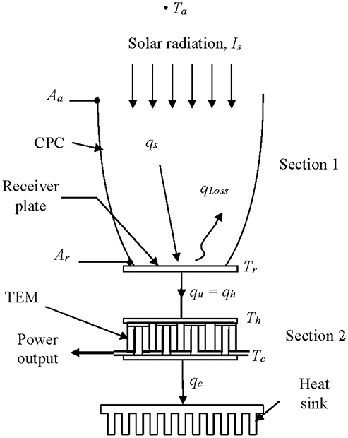
Figure 1. A schematic diagram of the hybrid system.
The hybrid 3D CPC/TEM system is a combination of a 3D CPC solar energy collector and a thermoelectric module as a unit and it has been shown that it is suitable for harnessing solar energy and generating electrical power (Mgbemene et al., 2010). The 3D CPC concentrates all solar radiation on it onto its focal point where an absorber plate is placed (Kreith and Kreider, 1978; Duffie and Beckman, 1991; Mgbemene et al., 2010). The setup is as shown in Figure 2. The CPC collects and converts solar energy to thermal energy while the TEM converts the thermal energy directly to electricity (Angrist, 1982). The CPC concentrates solar radiation onto a receiver plate raising its temperature, Tr. That CPC's receiver plate is attached to the hot junction of the TEM so that the heat generated on the receiver surface is conducted into the TEM maintaining the hot junction at a temperature, Th. The other junction is maintained at a lower temperature, Tc. Of major interest in such a system are Tr and Th. For electric power to be generated by the TEM, a temperature difference (Th – Tc), must be maintained across the two junctions. As long as the temperature difference is maintained across the TEM, the system continues to generate the electric power.
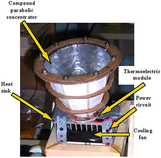
Figure 2. The experimental set-up showing the interior of the manually fabricated compound parabolic concentrator.
In a hybrid solar system for power generation, the concentrator type collector is more beneficial as its receiver could deliver higher temperatures than the non-concentrating types. Attempts have been made to develop rigorous mathematical models describing the behaviors of these concentrating collectors. A common type is the parabolic trough collector (PTC). Coccia et al. (2012) tested a mathematical model of a PTC and compared the efficiency predicted by the model with the efficiency measured through outdoor tests on a PTC prototype. Siqueira et al. (2014) developed and implemented a mathematical model to calculate flow parameters and heat transfer applied to parabolic trough solar collectors. Macedo-Valencia et al. (2014) presented a demonstrative prototype of a PTC for heating water. Tzivanidis et al. (2015) designed a small parabolic trough collector model and simulated its performance for different operating conditions. Their goal was to predict the efficiency of that model and to analyze the heat transfer phenomena that took place in it.
Kumar and Shukla (2016) designed a parabolic trough concentrator to produce optimum power. They established an empirical relation between the receiver area and aperture area and found a concentration ratio, CR with which they were able to achieve the maximum collection efficiency of the parabolic trough concentrator. Bendt et al. (1979) in their work described a macroscopic approach that yielded all the parameters needed for the optical design of line focus parabolic troughs in closed analytical form, requiring only minimal computation. They derived a formula for the optimal geometric concentration ratio.
Norton and Prapas in Garg et al. (1987) have developed a mathematical model describing the steady-state thermal behavior of a CPC solar energy collector and determined how the contribution of each particular mode of heat transfer affects the performance of the collector. Several other notable studies, including optical analysis of CPC, have been carried out (Rabl, 1976; Duffie and Beckman, 1991; Stine and Geyer, 2001; Wu, 2009; Manyala and Onyango, 2010; Nkwetta et al., 2010). Manyala and Onyango (2010) outlined the mathematical foundation in the evaluation or calculation of the geometric concentration ratio of most concentrators. Nkwetta et al. (2010) presented an optical analysis and comparative study of external concentrating single-sided absorber CPC (SSACPC) and double-sided absorber CPC (DSACPC) collectors designed to enhance the collection of solar radiation. Wu (2009) designed, fabricated and experimentally characterized an asymmetric compound parabolic photovoltaic concentrator (ACPPVC) for building façade integration with a solar concentration ratio of 2.0. He incorporated phase change materials to the rear of the PV panel to moderate the temperature rise of the PV and maintain good solar-electrical conversion efficiency. Rabl (1976) calculated the convective and radiative heat transfer through a CPC, and presented formulas for evaluating the performance of solar collectors based on the CPC principles. He went further to develop a simple analytic technique for calculating the average number of reflections for radiation passing through a CPC.
Hybrid systems involving solar thermoelectric power generation have also been studied. Eswaramoorthy and Shanmugam (2009) reported a feasibility study on the solar thermoelectric hybrid power generator which consisted of solar parabolic dish concentrator, thermoelectric generator and heat storage unit. Their study showed that such a hybrid system can meet all the energy needs of an ideal rural house. Mgbemene et al. (2010) studied a combination of a compound parabolic concentrator (CPC) and a thermoelectric module (TEM) for power generation. Their results showed that the combination can generate and sustain enough power for a small appliance with enough dissipated heat from the system, which could be harnessed for some other uses.
Shanmugam et al. (2011) carried out a mathematical modeling of a thermoelectric power generator driven by solar parabolic dish collector and presented that their results could be useful for further development of the system. Fan et al. (2011) experimentally investigation the performance of a concentrator thermoelectric generator (CTEG) utilizing solar thermal energy. The designed CTEG system consisted of a parabolic dish collector and four bismuth telluride based thermoelectric cells. The CTEG system was able to produce electric power of up to 5.9 W. Lertsatitthanakorn et al. (2014) studied a combination of a parabolic concentrator and a thermoelectric module and presented that under maximum heat flux, the module was able to produce 1.32 W at 2.89% conversion efficiency. Sundarraj et al. (2017) reported theoretical and experimental investigations of the electrical and thermal performance of a hybrid solar thermoelectric generator (HSTEG) using six thermoelectric generator modules. They were able to produce electrical power output of 4.7 W with an electrical efficiency of 1.2% and thermal efficiency of 61%.
Further studies could be found in Eswaramoorthy and Shanmugam (2013), Jarman et al. (2013), and Jeyashree et al. (2014). Most of the studies on the hybrid system however, dealt with parabolic concentrators or 2D CPCs. The 3D CPC/TEM system is not a common one and has not been well-studied previously. Mgbemene et al. (2010) and Senthilkumar et al. (2009) have studied the 3D CPC system but focused mainly on the use of the 3D CPC in power generation. Senthilkumar et al. (2009) mainly considered the calculation of the time constant of the 3D concentrator. There is therefore the need to further study and to characterize this unique system.
In solar collectors, the temperature of the receiver, the ambient temperature and the solar flux on the collector are strong parameters that affect the performance of the system. These parameters, lumped together as a ratio of the thermal input on the receiver to the insolation, when plotted against the instantaneous efficiency of collectors has been described as a figure of merit by which performances of collectors can be assessed (Garg et al., 1987). The lumped parameter has therefore, become a device parameter peculiar to the types of collectors. In this paper, it will be denoted as ψ and will represent the ratio of the maximum temperature difference in the CPC to the insolation on the receiver. Although the plots of this parameter for the CPC alone exists, none to the knowledge of the authors exists for the CPC/TEM system. It is particularly important for the CPC/TEM system because the temperature difference term here depends not only on the insolation but also on the thermoelectric effects. For the CPC, plots of collector thermal efficiency, ηc, against device parameter, ψ, curves have been given by Kreith and Kreider (1978), Garg et al. (1987) and Rabl (1976) but for the hybrid CPC/TEM system, there is no published ψ curve known to the authors. The aim of this write-up therefore, is to investigate the effects of the thermoelectric irreversibilities on the device parameter for the 3D CPC/TEM system which in turn affects the performance of the system, and to present the peculiar plots for the system.
The Analysis
The analysis of the performance of hybrid systems usually considers both the thermal performance, as well as the electrical output of the system. Following this in this paper, the analysis of the system shall consider both the thermal performance of the concentrator/TEM and the electrical performance of the TEM since the performance of the system depends on both.
The Lumped Parameter Formulation Without the Effect of Thermoelectric Irreversibilities
In this case, the system is the usual one where no TEM is attached to the receiver plate. The performance of the system (whether with TEM or without) largely depends on the performance of the CPC section of the system. The CPC here delivers the thermal energy to receiver plate.
The formulation of the lumped parameter begins with a look at the useful energy delivered by the collector. Carrying out an energy balance on the receiver plate (in Section 1 of Figure 1), we have that the useful energy, qu, delivered by the CPC is given as.
Since the analysis here is based on lumped parameters, it is assumed that all the heat loss terms can be parameterized by one quantityUL(TrCPC − Ta) (Kreith and Kreider, 1978; Duffie and Beckman, 1991). So that
The optical efficiency, ηo, of the concentrator collector is given as
(Kreith and Kreider, 1978; Garg et al., 1987)
Due to the shape of the CPC, only a part of the diffuse radiation incident on it effectively enters the CPC. The parameter that indicates the intercepted radiation by the CPC is denoted as δ.
The thermal efficiency, ηc, of the concentrator collector is given as
And substituting for qu in Equation (4)
Temperature difference occurs in each of the two sections of the system (Figure 1) and so the temperature difference in the collector for the system without the TEM shall be denoted as ΔTCPC so that
So Equation (9) could then be written as
The term is a dimensionless efficiency loss term and it represents the ratio of heat lost by the system to the heat input to the system from an external source. Equations (9) or (11) presents a linear relationship between ηc and ΔTCPC/Isprovided UL and CR are constants. For the CPC, the parameter ΔTCPC/Is can be extracted from the dimensionless efficiency loss term and be denoted as ψ. Equations (9, 11) can then be written in the form
where
ψ affects the parameter that defines the performance of a solar collector and is affected by the overall heat transfer coefficient, UL, of the collector but is dependent on CR, TrCPC, and Is. A plot of ηc vs. ψ will have a slope of UL/CR.
Effect of Thermoelectric Irreversibilities
For the TEM (Section 2 in Figure 1), when it is in operation, it comes under the influence of some physical processes which determine its performance. These physical processes are actually irreversibilities which occur in the thermoelectric system. The prominent ones are the finite rate heat transfer from one junction to the other by conduction in the thermoelectric device, the Joule resistive heat (actually an Ohmic heat production inside the thermoelectric device) and the Peltier effect. These are internal irreversibilities. The finite rate heat transfer by conduction and the Joule resistive heat act only within the boundaries of the TEM, while the Peltier effect, although it is an internal irreversibility, acts beyond the boundaries of the TEM. It causes more heat to be absorbed from the source into the thermoelectric system (Mgbemene, 2012).
The TEM is made up of several pairs of n- and p- semiconductor thermoelements. The irreversibilities affect the performance output of the TEM. The thermal energy passing through the system is as a result of the irreversibilities, and for N pairs of thermoelements, the heat drawn from a heat source, qh, and heat rejected to a heat sink, qc, are
and
αIT represents the Peltier heat, KΔT the conductive heat and I2R represents the Joule resistive heat through the system.
ΔT denotes the temperature difference in the TEM (Th - Tc).
And for a commercial TEM, as was used in this study, the current developed, I, is given as
The electrical power, P, developed by N thermocouples may be derived from the difference between Equations (14, 15) as
The conversion efficiency, Φ, of the TEM also known as its thermal efficiency, is defined as the ratio of the electrical power output, P, to the thermal power input, qh, to the hot junction and is given as
Effect of the TEM on the Heat Drawn From the CPC
The effect of the TEM on the heat drawn from the CPC can be shown in terms of the relationship between Tr and Th; and in terms of qh. To show this, let us consider the system where the TEM is attached to the receiver plate. Here the temperature of the receiver plate is as a result of the combination of the effects of the solar radiation and the thermoelectric irreversibilities. Since the receiver plate is lapped onto the TEM's hot junction, Th could be assumed to equal Tr if the thermal resistance between the receiver of the concentrator and the hot junction of the thermoelectric module is very small. Indeed it has been shown to be so (Mgbemene, 2012). Hence Tr is regarded to be equal to Th and the temperature of the receiver in this case becomes Tr(CPC/TEM). Therefore, we can now express ψ (CPC/TEM) as:
It should be noted that the magnitude of Th is basically determined by the action of the Peltier phenomenon. Hence, the magnitude of the value of Tr(CPC/TEM) will be different from that of the CPC alone. The ΔT in this case is (Tr(CPC/TEM) – Ta) and is influenced by both the CPC and TEM therefore, its effect on ψ in the CPC/TEM system is going to be different from that of CPC alone. Equations (13) and (22) show the relationship between ψ and Tr.
In terms of qh, recall Equation (4), the useful heat drawn from the CPC was given as qu. Based on the assumption that the thermal resistance between the receiver of the concentrator and the hot junction of the thermoelectric module is very small, we take qh to be equal to qu. Now in the CPC/TEM system, the Peltier effect affects the magnitude of this useful heat drawn from it and because of this effect more heat is drawn from the concentrator (Mgbemene, 2012). This implies that the qh (CPC/TEM) will be greater than qh (CPC).
Following this, the collector thermal efficiency of the hybrid system will be different from the collector thermal efficiency of the CPC alone and this will be given as
The system overall efficiency is a product of the efficiency of the CPC and that of the thermoelectric device. It is given as
Combining Equations (8, 21) we have
From Equation (25) we can write the overall efficiency to be
We can manipulate this equation to obtain
So the overall efficiency of the hybrid system becomes
The performance parameters of the system are related to the temperature of the collector receiver plate/hot junction of the TEM. For example, from the Equations (8, 11, 12, 13, 17–28), the efficiencies and the power output are functions of the collector receiver temperature, Tr or the TEM hot junction temperature, Th. The useful thermal energy, qu, passing through the system is a function of Th.
The System Model
To study the effects of thermoelectric irreversibilities on the 3D CPC/TEM system, and also the effect of the TEM on the heat drawn from the CPC, the system needs to be mathematically modeled. The system was modeled based on the ideal model and not by the finite rate heat transfer model (Mgbemene, 2012). This was because it was found that the effect of the thermal resistance between the copper receiver plate and the ceramic base is small implying a high thermal conductance between them. As a result, the temperature of the receiver plate was assumed equal to that of the adjoining ceramic base of the TEM. On the basis of this assumption, this method of analysis is termed the ideal model. Then combining Equations (4, 14), and where the accompanying terms are defined as presented in the write-up, the general equation describing the 3D CPC/TEM system can be written in terms of Th as (Mgbemene, 2012)
This can be rewritten as
where
represents the irreversibility due to Peltier effect,
represents the irreversibility due to conduction and
represents the irreversibility due to Joule resistive effect.
The term in parenthesis on the right hand side in Equation (30) is ψ.
The Experimental Setup
The model was experimentally validated with the setup shown in Figure 2. The compound parabolic concentrator was manually designed and fabricated. Its surface was covered with aluminum foil with reflectance coefficient of 0.86 (Duffie and Beckman, 1991). Based on that reflectance, the optical efficiency was calculated to be 0.58 (Kreith and Kreider, 1978).
The experimental performance of the CPC was tested in two different setups. First, the CPC was covered with a clear UV stabilized plastic material and in the second setup, the plastic material cover was removed. In both setups, a pyranometer was located at the focal point of the CPC and the readings were taken. The setup without cover gave higher pyranometer readings of 7167.2 W/m2. In the setup with cover, the measured pyranometer reading was 6055.6 W/m2 against the 945 W/m2 obtained from the pyranometer alone without being attached to the CPC. This 945 W/m2 is within the range of the average normal insolation obtained in Lowell, Massachusetts where the experiment was conducted. Ordinarily, it is expected that the setup without cover was going to record a lower value due to losses by convection, however it was found that the cover reflected more radiation back into the atmosphere than was lost by convection. Consequently, the setup without cover was employed for the experiment.
The CPC, without cover, was attached to a thin copper heat spreader which served as the collector receiver plate (placed at its focal point), which in turn was lapped onto a commercial TEM, Melcor thermoelectric module HT 6-12-40 with 127 pairs of thermoelements and a maximum specified temperature of 473 K. These formed the hot side of the TEG. The other surface of the TEM was coupled to a heat sink to form the cold side of the TEG. A Nidec TA350DC 12V dc cooling fan was then attached to the heat sink. These formed the 3D CPC/TEM system. The arrangement for the experimentation could be found in Mgbemene et al. (2010). Further details about the setup and its instrumentation could also be found in Mgbemene (2012).
The system was mounted on a manual tracker and the readings were taken for different periods of the day with the sun as the heat source. These readings were only taken when the pyranometer reading indicated a maximum insolation. The average reading of each set of readings was obtained. For the study, the following parameters were measured: solar radiation, ambient temperature, receiver plate temperature, and TEM cold side temperature. Others measured were: wind velocity, current and voltage outputs from the TEM. The measurements were made for the designed concentration ratio. The uncertainties in the measured data were analyzed as shown in Mgbemene et al. (2010).
Results and Discussion
The irreversibilities in the CPC/TEM system must have some effects on the performance of any adjoining system, more so, when one of the effects acts beyond the system's boundaries. So when the TEM is coupled to the CPC, the magnitude of the heat drawn, qu, from the receiver plate of the CPC is bound to be different from what it would have been if the CPC was standing alone. Therefore, the performance of the CPC/TEM system, which though largely depends on the performance of the CPC section, will be influenced by the behavior of the TEM.
Ordinarily the results of thermal performance tests of solar energy collectors (Kreith and Kreider, 1978), are given as plots of the instantaneous collector efficiency, ηc as a function of the difference in temperature between the collector plate and the ambient air (Tr – Ta), at different insolation values or of efficiency as a function of the solar flux incident on the collector, Is. But generally the results are better presented by combining the plots into one plot of the efficiency as a function of the ratio (Tr – Ta)/Is. This plot collapses several plots of efficiency as a function of the difference in temperature between the inlet to the collector and the ambient air and of efficiency as a function of the solar flux incident on the collector onto a single curve with a narrow band (Kreith and Kreider, 1978).
The plots, Figures 3–12, were made using EES software for CR values varying from 1 to 10 based on the values of the parameters shown in Table 1. Based on the model equation (Equation 29), the predicted plots showed a similar trend as could be seen from Figure 5. As result of the similarities, the predictions were experimentally validated at CR value of 10 because the concentration ratio affects the performance of the system. At this CR value the performance should be better seen than at lower CR values. The CPC was manually fabricated and the surface had some defects and was uneven. These resulted in some losses due to back reflection of energy back into the ambient. Hence there was quite a deviation between the predicted and experimental results (Figures 8–10). The specifications of the CPC and TEM used for the experimentation are shown in Tables 2, 3. Collector efficiency was plotted against temperature difference. The collector efficiency was again plotted against the insolation. ψ was then plotted against collector efficiency, conversion efficiency, overall efficiency and power output.
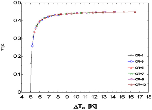
Figure 3. Collector efficiency ηc vs. temperature difference ΔTa at different concentration ratios.
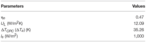
Table 1. The parameters and their values used for the analysis.
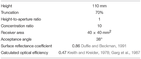
Table 2. The Specifications of the CPC used for the validation.
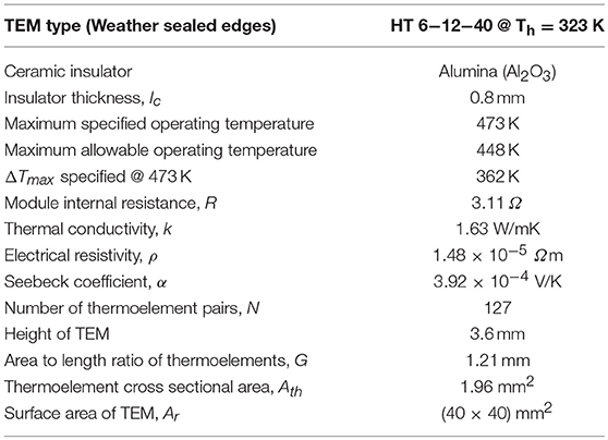
Table 3. The physical properties of the Melcor TEM used for the validation.
The predictions of the plots of ηc as a function of ΔT for the CPC/TEM system are presented in Figure 3 for CR values varying from 1 to 10. The curves are observed to be superimposed on one another to form a single continuous plot. The plots show the direct relationship between CR and Tr. CR directly affects the irreversibilities in the system as is also shown by Equation (30). As the CR value is increased and more heat is delivered at the receiver/hot junction of the system, the irreversibilities in the system are affected which in turn affect the Tr value and consequently, the ΔT.
In Figure 4, ηc for the CPC/TEM system is plotted against Is for CR values varying from 1 to 10. The efficiencies are seen to improve with increasing CR, however, the improvements are not appreciable beyond CR = 7.
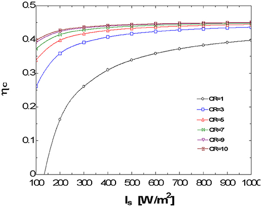
Figure 4. Collector efficiency ηc vs. insolation Is at different concentration ratios.
For flat plate collectors, a plot of the efficiency of the collector ηc vs. ψ most times results in a straight line but for concentrating collectors, it results in a curve (Kreith and Kreider, 1978). However, this 3D CPC/TEM system behaves like the flat plate collector. In this case the ηc vs. ψ curves are rather linear as shown in the predicted plots, Figure 5. The predicted plots were validated with plots based on experimental values i.e., the plot of ηc vs. ψ at CR = 10 (Figure 6). It presents a linear plot with a negative slope just like that of a flat plate collector. It does not take the form of a curve as should be expected since a CPC collector is employed here and as a first look at Equation (30) may imply. Figure 6 clearly shows that the plot is linearized despite the quadratic term in ΔT of Equation (30). It is most likely due to the nature of the irreversibility terms in that equation and their ultimate effect on ψ. The effect of the higher order term of ΔT in Equation (30) is not so significant as to make the plot to be non-linear. The effects of the Peltier and conduction terms are linear and they override the effect of the Joule resistive effect thereby linearizing the plot. Looking at that equation, UL and CR can have their values fixed which leaves ψ as the parameter that determines the value of ηc. This implies that in the design of such a system, at the desired CR value, and at an assumed value of UL, the efficiency of the system could be determined beforehand for every value of Is.
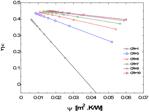
Figure 5. Collector efficiency ηc vs. system parameter ψ at different concentration ratios.
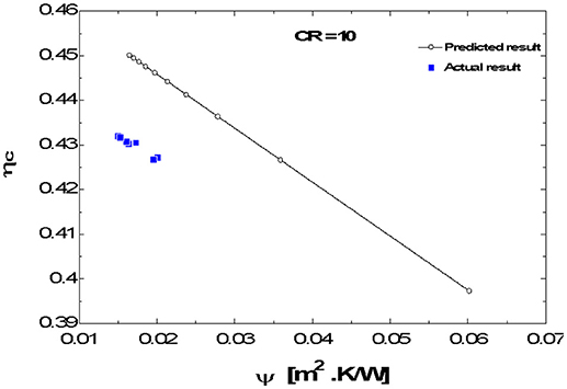
Figure 6. Collector efficiency ηc vs. system parameter ψ at CR = 10.
We had earlier established that ψ is strongly dependent on Tr which is affected by the irreversibilities in the system. The receiver/junction temperature, Tr, in this case is dependent on the parameters of the TEM as well as on those of the CPC unlike in the case of the concentrating solar collector alone without the TEM attachment. Here Tr is a function of the Is, external and internal irreversibilities of the system which contribute to the heating and cooling of the receiver plate. So the Tr for the CPC/TEM is not the same as that of the CPC alone.
For lower values of ψ, higher values of the efficiencies and power output are recorded (see Figures 7–10). A further look at the plot of P vs. ψ (Figure 8) for example, shows that at lower power output, the rate of change, dP/dψ, slows down. The same pattern is observed for the other plots. This indicates that Figures 7–10 all exhibit exponential decay nature. They are all of the form
where y represents the dependent parameter,
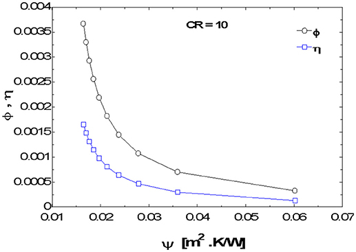
Figure 7. Conversion efficiency Φ, overall efficiency η vs. system parameter ψ at CR = 10.
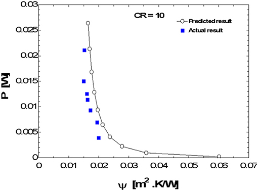
Figure 8. Power output P vs. system parameter ψ at CR = 10.
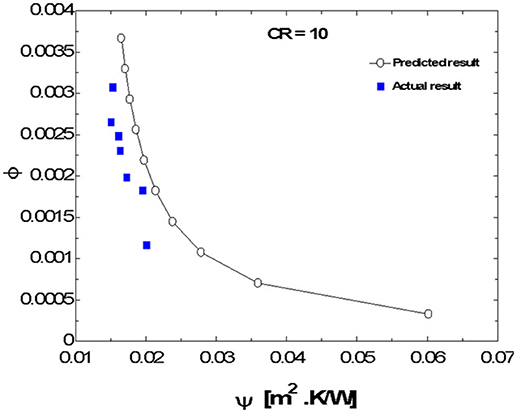
Figure 9. Conversion efficiency, Φ, vs. system parameter ψ at CR = 10.
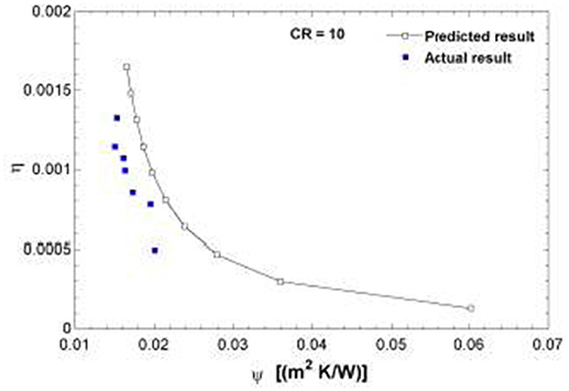
Figure 10. Overall efficiency, η, vs. system parameter, ψ, at CR = 10.
a = the maximum value,
b = the percentage change =
(1 – b) = the decay factor
x = the device performance parameter, ψ.
The nature of the plots is largely due to the interactions of the irreversibilities within the system. From the plots, it can be seen that as ψ increases, the performance of the system drops.
Useful Range of Ψ Value
Figure 11 is a plot of ψ vs. Is. The dependence of ψ on Is can be deduced from it. It also shows the range of useful value of ψ in terms of insolation. The range of usefulness of ψ can be easily seen from the plot of Figure 11 when considered with the other plots (Figures 3–10). For the overall performance of the system, the plot of η vs. ψ (Figure 10) could be used in determining that. A certain range of values of ψ corresponds with reasonable values of the dependent parameter in the plots. That range is the desirable range for good performance of the system. Beyond that, the performance of the system becomes undesirable. ψ operates indirectly proportional to the performance parameters of the system. For example, considering power output of the system, the lowest useful insolation could be taken as 300 W/m2 corresponding to ψ value of 0.028 (Figure 11) and power output of about 0.002 W (Figure 8). If we take the maximum insolation to be 1,000 W/m2, then the corresponding value of ψ will be 0.015. Hence the desirable range of ψ will be 0.028 ≥ ψ ≥ 0.015 at CR = 10. This range is unique to CR and will differ with its value.
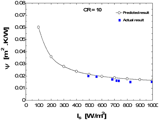
Figure 11. System parameter ψ vs. insolation Is at CR = 10.
Prediction of the Receiver Plate Temperature
For a given collector, ηo is given. Consequently, if UL could be guessed, and since CR is already fixed, Is and Ta are known, ψ could be used to predict the receiver plate temperature Tr and the efficiencies η, ηc of the system. Therefore ψ could be used in determining the receiver plate temperature for a given concentration ratio. As an example, from Equation (22)
At Is = 1,000 W/m2 corresponding to ψ = 0.015 from Figure 11 at Ta = 300 K we can obtain the value of Tr to be 315 K. This is in agreement with the value of ψ in Figure 12.
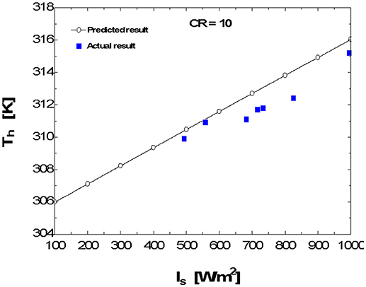
Figure 12. Comparison of the predicted and the actual results of the plots of hot junction temperature Th vs. insolation Is at CR = 10.
The plot of ηc vs. ψ (Figure 6) could also be useful in the determination of UL. For example, from the plot made at a given CR, since the slope of the plot is UL /CR and the CR value is known, the UL value could be calculated from it.
Conclusion
The effects of the device performance parameter ψ on the hybrid 3D CPC/TEM system due to thermoelectric irreversibilities have been investigated. The dependence of the parameter on the thermoelectric irreversibilities was highlighted. The parameter, ψ, linearizes the plot of ηc vs. ψ and makes the plots of other output parameters against ψ to exponentially decay. It can be concluded that it is due to the nature of ψ. The device parameter, ψ, is strongly dependent on Tr (Th) which is affected by the irreversibilities in the system. It can also be concluded that the nature of ψ must be due to the thermoelectric irreversibilities. This highlights the fact that the 3D CPC/TEM system is unique and requires that further characterization be carried out on it. The plots help in determining the desirable range for good performance of the system. Lastly, it can be concluded that ψ could be useful in the determination of the values of the receiver plate temperature and the heat loss from the collector.
Author Contributions
CM drafted the manuscript while HN and CA read and improved on it. All authors read and approved the submitted version.
Conflict of Interest Statement
The authors declare that the research was conducted in the absence of any commercial or financial relationships that could be construed as a potential conflict of interest.
References
Bakić, V., Pezo, M., Stevanović, Ž., Živković, M., and Grubor, B. (2012). Dynamical simulation of PV/wind hybrid energy conversion system. Energy 45, 324–328. doi: 10.1016/j.energy.2011.11.063
Bendt, P., Rabl, A., Gaul, H. W., and Reed, K. A. (1979). Optical Analysis and Optimization of Line Focus Solar Collectors. Available online at: https://www.researchgate.net/publication/242069921_Optical_analysis_and_optimization_of_line_focus_solar_collectors (Accessed April 25, 2018).
Coccia, G., Latini, G., and Sotte, M. (2012). Mathematical modeling of a prototype of parabolic trough solar collector. J. Renew. Sustain. Energy 4:023110. doi: 10.1063/1.3699620
Duffie, J. A., and Beckman, W. A. (1991). Solar Engineering of Thermal Processes. New York, NY: Wiley Interscience.
Eid, A. (2014). Utility integration of PV-wind-fuel cell hybrid distributed generation systems under variable load demands. Int. J. Elect. Power Energy Syst. 62, 689–699. doi: 10.1016/j.ijepes.2014.05.020
Ekren, O., and Ekren, B. Y. (2010). Size optimization of a PV/wind hybrid energy conversion system with battery storage using simulated annealing. Appl. Energy 87, 592–598. doi: 10.1016/j.apenergy.2009.05.022
Engin, M. (2013). Sizing and simulation of PV-wind hybrid power system. Int. J. Photoenergy 10:217526. doi: 10.1155/2013/217526
Eswaramoorthy, M., and Shanmugam, S. (2009). A feasibility study on solar thermoelectric hybrid power generation. Proc. Int. Conf. on Energy Environ. 51, 431–354.
Eswaramoorthy, M., and Shanmugam, S. (2013). Solar parabolic dish thermoelectric generator: a technical study. Energy Sour. 35, 487–494. doi: 10.1080/15567036.2010.504945
Fan, H., Singh, R., and Akbarzadeh, A. (2011). Electric Power generation from thermoelectric cells using a solar dish concentrator. J. Electron. Mater. 40. 1311–1320. doi: 10.1007/s11664-011-1625-x
Gao, X., Andreasen, S. J., Kaer, S. K., and Rosendahl, L. A. (2014). Optimization of a thermoelectric generator subsystem for high temperature PEM fuel cell exhaust heat recovery. Int. J. Hydrogen Energy 39, 6637 – 6645. doi: 10.1016/j.ijhydene.2014.01.193
Garg, H. P., Dayal, M., Furlan, G., Sayigh, A. A. M., and Sharma, V. K. (1987). “Physics and technology of solar energy,” in Solar Thermal Applications, Vol. 1, eds D. Holland (Dordrecht: Reidel Publishing Co.), 39–135.
Jarman, J. T., Khalil, E. E., and Khalaf, E. (2013). Energy analyses of thermoelectric renewable energy sources. Open J. Energy Efficien. 2, 143–153. doi: 10.4236/ojee.2013.24019
Jeyashree, Y., Juliet, A. V., and Joseph, A. A. (2014). “Experimental analysis of thermoelectric generator using solar energy,” in 2014 International Conference on Smart Structures and Systems (ICSSS) (Chennai), 67–71. doi: 10.1109/ICSSS.2014.7006197
Kong, L., Cai, G., Xue, S., and Li, S. (2015). Modeling and coordinated control strategy of large scale grid-connected wind/photovoltaic/energy storage hybrid energy conversion system. Math. Prob. Eng. 2015:14. doi: 10.1155/2015/682321
Kreith, F., and Kreider, J. E. (1978). Principles of Solar Engineering. Washington, DC: Hemisphere Publishing Corp.
Kumar, A., and Shukla, S. K. (2016). Mathematical modeling and optimization of a parabolic trough concentrator for the improvement of collection efficiency. Int. J. Innov. Res. Eng. Manage. 3, 375–380. Available online at: http://www.ijirem.org/DOC/1_REM37981861230-f1b0-4bde-9b54-fb4ca489966b.pdf
Lertsatitthanakorn, C., Jamradloedluk, J., and Rungsiyopas, M. (2014). Electricity generation from a solar parabolic concentrator coupled to a thermoelectric module. Energy Proc. 52, 150–158. doi: 10.1016/j.egypro.2014.07.065
Macedo-Valencia, J., Ramírez-Ávila, J., Acosta, R., Jaramillo, O. A., and Aguilar, J. O. (2014). Design, construction and evaluation of parabolic trough collector as demonstrative prototype. Energy Procedia 57, 989–998. doi: 10.1016/j.egypro.2014.10.082
Makki, A., Omer, S., and Sabir, H. (2015). Advancements in hybrid photovoltaic systems for enhanced solar cells performance. Renew. Sustain. Energy Rev. 41, 658–684. doi: 10.1016/j.rser.2014.08.069
Manyala, R., and Onyango, F. (2010). “Some techniques in configurational geometry as applied to solar collectors and concentrators,” in Solar Collectors and Panels, Theory and Applications, eds R. Manyala (InTech). Available online at: https://www.intechopen.com/books/solar-collectors-and-panels--theory-and-applications/some-techniques-in-configurational-geometry-as-applied-to-solar-collectors-and-concentrators (Accessed December 6, 2014).
Mgbemene, C. A. (2012). Solar Thermoelectric Power Generation: Using Compound Parabolic Concentrators (Monograph). Saarbrucken: LAP LAMBERT Academic.
Mgbemene, C. A., Duffy, J., Sun, H., and Onyegegbu, S. O. (2010). Electricity generation from a compound parabolic concentrator coupled to a thermoelectric module. ASME J. Sol. Energy Eng. 132:8. doi: 10.1115/1.4001670
Michel, B., and Paredes, S. (2013). Combining photovoltaic and thermal systems for efficiency gains. SPIE Newsroom. doi: 10.1117/2.1201308.005011
Nkwetta, D. N., Smyth, M., Zacharopoulos, A., and Hyde, T. (2010). Optical Analysis and Comparison of Single-Sided Absorber CPC (SSACPC) and Double-Sided Absorber CPC (DSACPC) Collectors. Available online at: http://proceedings.ases.org/wp-content/uploads/2014/02/2010-028small.pdf (Accessed December 7, 2014).
Otanicar, T. P., Theisen, S., Norman, T., Tyagi, H., and Taylor, R. A. (2015). Envisioning advanced solar electricity generation: parametric studies of CPV/T systems with spectral filtering and high temperature PV. Appl. Energy 140, 224–233. doi: 10.1016/j.apenergy.2014.11.073
Othman, M., Yatim, B., Sopian, K., and Bakar, M. (2006). Double-pass photovoltaic-thermal solar air collector with compound parabolic concentrator and fins. J. Energy Eng. 132, 116–120. doi: 10.1061/(ASCE)0733-9402(2006)132:3(116)
Parise, J. A., Vargas, J. V., and Pitanga, M. R. (2008). Fuel cells and cogeneration. J. Fuel Cell Sci. Technol. 5:13. doi: 10.1115/1.2889018
Pérez-Collazo, C., Greaves, D., and Iglesias, G. (2015). A review of combined wave and offshore wind energy. Renew. Sustain. Energy Rev. 42, 141–153. doi: 10.1016/j.rser.2014.09.032
Rabl, A. (1976). Optical and thermal properties of compound parabolic concentrators. J. Sol. Energy 18, 497–511. doi: 10.1016/0038-092X(76)90069-4
Riffat, S. B., and Ma, X. (2003). Thermoelectrics: a review of present and potential applications. J. Appl. Therm. Eng. 23, 913–935. doi: 10.1016/S1359-4311(03)00012-7
Senthilkumar, S., Perumal, K., and Srinivasan, P. S. S. (2009). Optical and thermal performance of a three-dimensional compound parabolic concentrator for spherical absorber. Sādhanā 34, 369–380. doi: 10.1007/s12046-009-0017-x
Shanmugam, S., Eswaramoorthy, M., and Veerappan, A. R. (2011). Mathematical modeling of thermoelectric generator driven by solar parabolic dish collector. Appl. Sol. Energy 47, 31–35. doi: 10.3103/S0003701X11010154
Siqueira, A. M., Gomes, P. E. N., Torrezani, L., Lucas, E. O., and Pereira, G. M. (2014). Heat transfer analysis and modeling of a parabolic trough solar collector: an analysis. Energy Procedia 57, 401–410. doi: 10.1016/j.egypro.2014.10.193
Stine, W. B., and Geyer, M. (2001). Power From the Sun. Available online at: www.powerfromthesun.net (Accessed December 7, 2014).
Sundarraj, P., Taylor, R. A., Banerjee, D., Maity, D., and Roy, S. S. (2017). Experimental and theoretical analysis of a hybrid solar thermoelectric generator with forced convection cooling. J. Phys. D: Appl. Phys. 50:11. doi: 10.1088/1361-6463/50/1/015501
Surith, N. M., Vishnu, V. D., Raam kumar, P. H., Sai, P. S., and Ramya, K. (2013). Photovoltaic driven dual purpose thermoelectric refrigerator for rural India. Int. J. Adv. Res. Technol. 2, 111–117. Available online at: http://www.ijoart.org/docs/Photovoltaic-Driven-Dual-Purpose-Thermoelectric-Refrigerator-for-Rural-India.pdf
Tripanagnostopoulos, Y., Nousia, T. H., Souliotis, M., and Yianoulis, P. (2002). Hybrid photovoltaic/thermal solar systems. Sol. Energy 72, 217–234. doi: 10.1016/S0038-092X(01)00096-2
Tyagi, V. V., Kaushik, S. C., and Tyagi, S. K. (2012). Advancement in solar photovoltaic/thermal (PV/T) hybrid collector technology. Renew. Sustain. Energy Rev. 16, 1383–1398. doi: 10.1016/j.rser.2011.12.013
Tzivanidis, C., Bellos, E., Korres, D., Antonopoulos, K. A., and Mitsopoulos, G. (2015). Thermal and optical efficiency investigation of a parabolic trough collector. Case Studies Thermal Eng. 6, 226–237. doi: 10.1016/j.csite.2015.10.005
Wu, Y. (2009). Thermal Management of Concentrator Photovoltaics. Unpublished Ph.D. Thesis. University of Warwick, Coventry. Available online at: http://wrap.warwick.ac.uk/3218/1/WRAP_THESIS_Wu_2009.pdf (Accessed December 7, 2014).
Zhang, L., Jing, D., Zhao, L., Wei, J., and Guo, L. (2012). Concentrating PV/T hybrid system for simultaneous electricity and usable heat generation: a review. Int. J. Photoenergy 2012:8. doi: 10.1155/2012/869753
Nomenclature
Aa concentrator aperture area (m2)
Ar concentrator receiver area (m2)
Ath cross-sectional area of a single thermoelement (m2)
CR concentration ratio of the collector
I electric current developed (A)
Ib, c beam radiation incident on collector receiver plate (W/m2)
Id, c diffuse radiation incident on the collector receiver plate (W/m2)
Issolar radiation on the collector (W/m2)
K the thermal conductance (W/K)
L thermoelement length (m)
N number of thermoelement pairs
n- negatively doped thermoelement
average number of reflections
P electrical power output (W)
p- positively doped thermoelement
qc thermal energy rejected to the heat sink (W)
qh thermal energy input to the TEM (W)
qLoss energy loss from concentrator (W)
qs thermal energy input due to solar radiation (W)
qu useful energy gain (W)
R internal electrical resistance of a thermoelectric couple (Ω)
Ta ambient temperature (K)
Tc TEM's cold junction temperature (K)
Th TEM's hot junction temperature (K)
Tr collector receiver plate temperature (K)
UL the overall heat loss coefficient (W/m2 K)
Greek Letters
α cover absorptance, or Seebeck coefficient (V/K)
δ intercepted radiation parameter
η overall efficiency
ηc collector thermal efficiency
ηo collector optical efficiency
ρ average electrical resistivity of thermoelement material (Ω-m)
ρm specular mirror reflectance
τ transmittance
ϕ conversion efficiency of TEM
ψ device performance parameter (m2 K/W)
Keywords: compound parabolic concentrator, receiver plate temperature, solar thermoelectric generator, thermoelectric module, thermoelectric irreversibilities
Citation: Mgbemene CA, Njoku HO and Agbo COA (2018) Investigation of Parametric Performance of the Hybrid 3D CPC/TEM System Due to Thermoelectric Irreversibilities. Front. Energy Res. 6:101. doi: 10.3389/fenrg.2018.00101
Received: 20 June 2018; Accepted: 07 September 2018;
Published: 01 October 2018.
Edited by:
Tayebeh Ameri, Universität München, GermanyReviewed by:
Nuo Yang, Huazhong University of Science and Technology, ChinaKrishnan Srinivasan Annur, Coimbatore Institute of Technology, India
Copyright © 2018 Mgbemene, Njoku and Agbo. This is an open-access article distributed under the terms of the Creative Commons Attribution License (CC BY). The use, distribution or reproduction in other forums is permitted, provided the original author(s) and the copyright owner(s) are credited and that the original publication in this journal is cited, in accordance with accepted academic practice. No use, distribution or reproduction is permitted which does not comply with these terms.
*Correspondence: Chigbo Aghaegbusi Mgbemene, Y2hpZ2JvLm1nYmVtZW5lQGdtYWlsLmNvbQ==