 Ajla Aksamija
 Zlatan Aksamija2
- 1Department of Architecture, University of Massachusetts Amherst, Amherst, MA, United States
- 2Department of Electrical and Computer Engineering, University of Massachusetts Amherst, Amherst, MA, United States
This article discusses the application of thermoelectric (TE) materials in building facade systems, which can be used to create active exterior enclosures. TEs are semiconductors that have the ability to produce a temperature gradient when electricity is applied, exploiting the Peltier effect, or to generate a voltage when exposed to a temperature gradient, utilizing the Seebeck effect. TEs can be used for heating, cooling, or electricity generation. In this research, heating and cooling applications of these novel systems were explored. We designed and constructed two prototypes, where one prototype was used to study integration of TE modules (TEMs) as stand-alone elements in the facade, and one prototype was used to explore integration of TEMs and heat sinks in facade assemblies. Both prototypes were tested for heating and cooling potential, using a thermal chamber to represent four different exterior environmental conditions (−18°,−1°,16°, and 32°C). The interior ambient conditions were kept constant at room temperature. The supplied voltage to facade-integrated TEMs varied from 1 to 8 V. We measured temperature outputs of TEMs for all investigated thermal conditions using thermal imaging, which are discussed in this article. The results indicate that while stand-alone facade-integrated TEMs are not stable, addition of heat sinks improves their performance drastically. Facade-integrated TEMs with heatsinks showed that they would operate well in heating and cooling modes under varying exterior environmental conditions.
Introduction
Buildings consume 40% of energy in the United States, and influence greenhouse gas emissions. High demand for energy used for lighting, heating, ventilation, and air conditioning leads to significant amount of carbon dioxide emissions. According to the U.S. Department of Energy, 15% of global electricity is consumed by various refrigeration and air-conditioning processes, and 46% of the energy used in household and commercial buildings is attributed to heating, ventilation and air-conditioning (HVAC) systems (Department of Energy, 2011). Given the high energy usage and inefficiencies found in conventional HVAC systems, new heating and cooling sources are needed in order to reduce buildings' carbon footprint. Moreover, integration of different building systems, particularly building envelope and HVAC, are essential for high-performance buildings. Building envelope impacts more than half of typical energy usage in buildings, since it influences thermal performance, heating, cooling, ventilation and lighting (Aksamija, 2013). New passive and active technologies that can improve performance of facade systems are currently of great interest.
Thermoelectrics are one example of a promising technology with potential architectural applications. Research and development has largely focused on thermoelectric modules (TEMs) that convert heat energy into electrical energy (Montecucco et al., 2012; Yilmazoglu, 2016). Heating and cooling modes can be switched by reversing the current direction (Figure 1), while the “Power Input” supply module can be microprocessor-controlled to make the TEM responsive to the environment through a combination of sensors and closed-loop digital control. TEMs can offer small-scale and relatively low-cost electricity generation without the use of mechanical parts or production of toxic waste (Seetawan et al., 2014). The optimal performance of TEMs depends on many factors, ranging from material selection to operation strategy (Twaha et al., 2016).
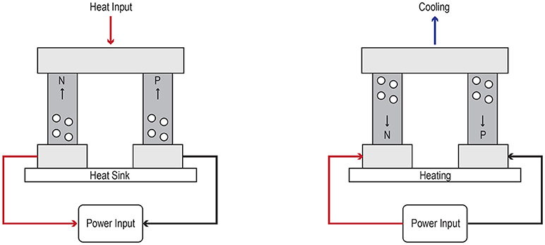
Figure 1. Thermoelectric materials produce electricity when exposed to thermal gradient, and cooling/heating when voltage is applied.
TEMs can be used for heating, cooling, or electricity generation, as shown in Figure 2. TEMs consist of arrays of N and P type semiconductors. When a heat source is applied on one side of the semiconductor and the other side is exposed to a cooler temperature, electricity is produced. Electricity supply can actively provide cooling or heating by reversing the current direction (Zheng et al., 2014). In this research, applications of TEMs in facade systems, as well as cooling and heating potentials were explored. The research questions that were addressed include:
• How can TE materials be integrated into architectural facade assemblies to provide localized heating and cooling?
• How do TE materials behave in typical climate thermal conditions?
• How do varying voltages, climatic conditions and assembly construction affect TE materials' thermal performance?
• How is TE materials' performance affected by different configuration of heat sinks?
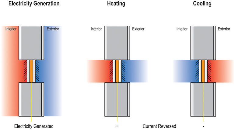
Figure 2. Potential use of TE materials in exterior walls for energy generation, heating and cooling.
Literature Review
Most research into TE materials conducted before 2005 concentrated on increasing the TE figure-of-merit ZT, a dimensionless measure of conversion efficiency, through materials selection. Research focused on variations of geometric features such as shape, size, and orientation to the flow in heat transfer systems. More recently, research on TE applications has gained momentum (Zhao and Tan, 2014; Twaha et al., 2016). A promising, but not widely researched area, includes use of TEs for targeted, localized heating and cooling in buildings.
In the past 15 years, significant growth of research into thermoelectric energy conversion is reflected in the increase in related annual publications (Bell, 2008). TEMs have been used for cooling and heating applications in the military and aerospace fields, and for electronic instruments (Kraemer et al., 2011). Since TEMs do not contain any moving parts, they are very compact in size, while their operation is quite reliable and stable. This greatly reduces maintenance costs when compared to other types of air conditioning systems (Shen et al., 2013). It is possible to use TEMs as an alternative to HVAC applications with properly designed heat exchangers (Yilmazoglu, 2016).
Thermoelectric heating and cooling has several advantages over conventional counterparts. The compact size, light-weight, reliability, lack of mechanical parts and elimination of the need for chlorofluorocarbons make them environmentally friendly and appealing. But, applying thermoelectric systems for space heating and cooling remains much more challenging and has not been explored beyond small scale applications and in theoretical proposals (Zhao and Tan, 2014; Zuazua-Ros et al., 2018). Two possible reasons might be relatively low efficiency of TEMs compared to high-efficiency HVAC systems, and relatively high costs. However, recent developments show promise in new classes of TEs that improve energy output and reduce manufacturing costs (Schonecker et al., 2015). The conversion efficiency of TEs has also been steadily rising because of the intensified research into abundant, naturally-occurring, and efficient TE materials. Furthermore, economies of scale have been steadily exerting downward pressure on the prices of TEMs as they reach market penetration; currently, TEMs are commercially available with costs below the 1$/W mark. The key driver of the cost remains the overall assembly and installation, including heat exchangers, power supplies, and control systems.
Few applications of TEM's in facade assemblies have been researched, proposed, or constructed. This has created a significant gap in knowledge in the potential architectural applications of TEM's. Some researchers, however, have proposed architectural applications with promising preliminary results. Liu et al. proposed a facade assembly that integrates TEM with a heat sink for heating and cooling needs (Liu et al., 2015). Results indicate that the total input power required to operate a TEM decreases as the distribution density of the TEMs increase. The thermal resistance of the heat sink plays an important role in determining the number of TE coolers optimizing all potential design configurations (Liu et al., 2015). This study proposed a window composed of four parts: a passive window, a PV module, thermoelectric cooling units, and heat sinks. A semi-transparent PV module is integrated into the front pane of a passive double-pane window and it is used to power TEMs integrated into the window frame. Finned heat sinks are placed in contact with the TE units to control the heat transfer between the TEMs and the ambient environment. The PV unit converts solar radiation into electrical energy, while the TEMs change this electrical energy into thermal energy. The TEMs can heat or cool, depending on the direction of the current supplied by the PV unit. This would allow the building envelope to be used in both heating and cooling applications (Liu et al., 2015).
Ibanez-Puy et al. investigated prototype of a modular active ventilated facade, which includes TE modules within the air cavity (Ibanez-Puy et al., 2015). This study reports on the design process of a prototype, materials and assembly, and discusses experimental set-up, but the results of the experimental study were not reported.
Since integration of TE materials in facade systems offers a promising opportunity to create active, intelligent enclosures that provide localized heating and cooling, as well as energy generation, this study focused on the design, development and experimental investigation of prototypes.
Research Methods
Prototype Development
Two facade prototypes with integrated TE materials were assembled for the purposes of this study. These prototypes were designed and constructed to represent interior thermal components of typical facade systems (i.e., insulation layer) with integrated TE materials, but the cladding material and structural components were not included. The prototypes were tested in ambient and thermally controlled conditions to measure temperature gradients, heating and cooling potential. Materials for these assemblies were selected for their commercial availability, low cost, as well as specifications. Two heat sink types were chosen to provide a comparison in heat transfer performance values.
The dimensions of utilized TEMs are 40 × 40 mm (1.6 × 1.6 in), drawing up to 12 V, with operating conditions from −30°C (−22°F) to 83°C (181.4°F). Small heat sinks of 40 × 40 × 11 mm (1.6 × 1.6 × 0.4 in), composed of aluminum cooling fins, were used to provide direct heat sinks for a flat heat sink assembly. These were fixed to the TEMs using 0.5 mm (0.02 in) silicone based thermal pads. The second prototype included larger heat sinks. Two 120 mm (4.7 in) heat sinks were used, with four direct heat copper pipes for heat dissipation to an array of fins. Thermal paste provided a thermal connection to the TEM.
Five configurations were considered when constructing prototypes for testing, as shown in Figure 3. A direct contact TE facade module would provide the simplest assembly, applying heat sinks directly to the TEM. This assembly, however, poses the greatest potential for thermal bridging and gaps in the facade assembly. A sink transfer assembly expands upon the direct contact assembly, but relies on conductors to transfer heat from the TEM to heat sinks. Location shift assemblies are similar to sink transfer assemblies, but allow flexibility for heat sink location in relation to the TEM. Stacked TEMs provide the opportunity to increase the temperature differences between the hot and cold sides beyond what is possible with a single TEM across multiple modules. Floor mounted assemblies consider integrating TEMs, conductors, and heat sinks into the floor plate and facade. This assembly is the most complicated application, but provides benefits that include natural convection and heat sink concealment.
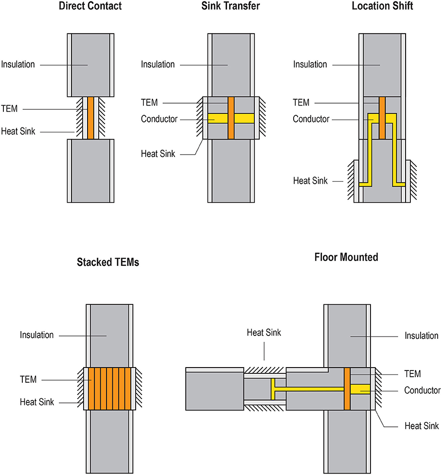
Figure 3. Schematic representation of possible configuration and placement of TEMs in facades.
For the purposes of this research, direct contact (Figure 4) and sink transfer TEM (Figure 5) facade assemblies were selected, for their simplicity and broad applicability. Each assembly was constructed using two 2.54 cm (1 in) thick foam insulation panels with an R-value of 0.88 m2·°C/W (5 ft2·°F·h/BTU), providing each assembly with an R-value of 1.76 m2·°C/W (10 ft2·°F·h/BTU), shown in Figure 6. Thin board (3.175 mm or 1/8 in) was glued to the face of foam insulation and provided a housing within the assembly for the TEMs and heat sinks. Heat sinks were inserted into the assembly and connected to the TEM using thermal paste or thermal pads. The flat assembly did not rely on any fasteners to connect the TEMs to the heat sinks, instead thermal pads provided the adhesion. The large heat sink assembly required an assembly composed of nuts, bolts, and washers to sandwich the TEM, foam, and board assembly together. Spray foam insulation was applied to the larger heat sink assembly to prevent any thermal breaks that may have developed through use of metal hardware and fasteners.
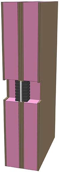
Figure 4. Architectural proof of concept model section for thermoelectric facade (direct contact assembly).
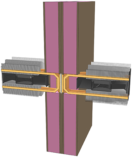
Figure 5. Architectural proof of concept a model section for thermoelectric facade (sink transfer assembly).
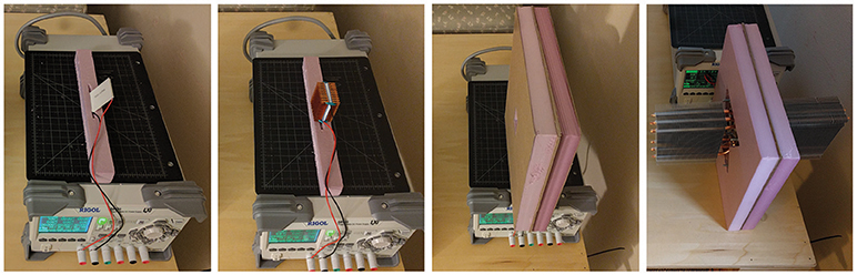
Figure 6. Thermoelectric facade proof of concept mockups.
Prototype Testing
To understand how facade-integrated TE materials behave, these prototypes were first tested in ambient room conditions, with temperature of 22.2°C (72°F). An independent module without a heat sink, a module with a flat heat sink, as well as the assembly mockups were tested with applied voltage of 1 V increments. These tests were performed to understand how facade-integrated TEMs would behave, prior to conducting a thermal chamber test. Results were measured using thermal imaging camera and a power supply. Thermal images were taken at one volt increments up to 8 V, and temperatures were recorded using a thermal camera with numerical temperature read-out with resolution of 0.1°.
Further testing involved the use of a temperature controlled thermal chamber, model Tenney Jr. The thermal chamber's 42 × 42 cm (16.5 × 16.5 in) opening was sealed using 2.54 cm (1 in) of insulating foam with tape applied to provide a relatively air tight seal for the testing. Assemblies were inserted into a 25 × 25 cm (10 × 10 in) void, and were taped again (Figure 6). This allowed for easy insertion and removal of the prototypes. The chamber was set to −18°, −1°, 16°, and 32°C (0°, 30°, 60°, and 90°F respectively) to represent different exterior temperatures (winter, summer and intermediate seasons). This method of testing simulated typical exterior temperatures found in most climates while allowing for temperature data to be collected in a controlled setting. For the heating mode, exterior temperatures of −8°, −1°, and 16°C (0°, 30°, and 60°F) were applied. For the cooling mode, exterior temperatures of 16° and 32°C (60° and 90°F) were used.
The thermal chamber was allowed time to stabilize (60 min before each testing session, and 20 min breaks were taken in between each measurement. The ambient temperature of the room was kept relatively stable at 23°C (73°F). Voltage was applied in 1 V increments in both heating and cooling modes. Temperature measurements on the exterior surface of the prototypes were recorded using a thermal camera, shown in Figure 7. The setting for emissivity in the thermal camera was set to 0.1 in order to match the aluminum surface of the heat sink, and this was used for all measurements. The temperature was determined from the values in the center of the image, while the camera was pointed at the aluminum heat sink. The temperature was first measured without TEMs operating to establish a baseline, and then the second measurement was taken after the system has stabilized to determine ΔT. These values were recorded, and are presented in the next section.
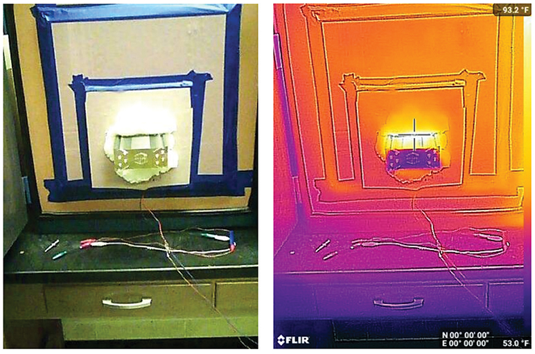
Figure 7. Assembly testing in thermal chamber with thermal imaging.
Results
Ambient Testing Results: Heating and Cooling
Results were collected, tabulated, and graphed for analysis. The temperatures observed in ambient testing ranged from 9.3°C (48.8°F) to 125.7°C (258.3°F) in both cooling and heating modes. The maximum temperature observed occurred on the hot side of the flat heat sink at 8 V. The independent TEM approached this value, reaching 114.6°C (238.2°F) at 6 V before module failure. Heating side maximums exceeded 93.3°C (200.0°F) in all ambient assembly tests, except for the large heat sink, since measured temperature for of this assembly was 36.3°C (98.3°F) at 8 V. All heating side temperatures show positive temperature trends, as shown in Figure 8.
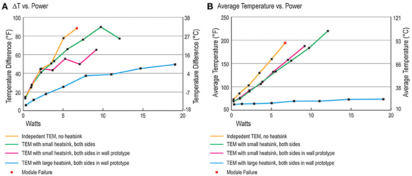
Figure 8. (A) Temperature difference and (B) average temperature results in ambient conditions.
Cooling temperatures displayed inconsistent data. Temperatures ranged from 9.3°C (48.8°F) to 82.8°C (181.1°F). Cold side temperatures elevate significantly on the independent TEM, flat heat sink, and flat heat sink assembly above 4 V. The cold side temperatures of these testing modules exceed 37.8°C (100.0°F) at or around 4 V. The large heat sink shows temperatures ranging from 15.3°C (59.5°F) to 9.3°C (48.8°F). The temperature difference and average temperature values were the lowest for this assembly.
Modules without heat sinks were stressed by high temperature difference values, often times exceeding those suggested by the manufacturer. Average temperatures show similar stresses, and can reach or exceed 93.3°C (200.0°F). TEM failures occurred on several occasions, most notably when TEMs were not paired with heat sinks, or if voltages exceeded 8 V. This is caused by poor thermal coupling to the environment: when the heat removal from the TEM to the environment is inefficient, the TEM overheats and fails. Only the large heat sink maintained a stable average temperature, stressing the importance of incorporating a properly-sized heat sink with minimal thermal resistance for the proper functioning and reliability of facade-integrated TEMs.
Thermal Chamber Testing Results: Heating
Results of the thermal chamber testing indicate that the temperature values increase as higher voltages are applied, regardless of the assembly type or tested temperature (Figure 9). The results for the prototype with a large heat sink show that temperatures range from 13.6°C (56.4°F) to 36.2°C (97.1°F) when applied in 1 V increments. Values always remained above −17.8°C (0°F) temperature. −1.1°C (30.0°F) ambient temperature data show values rising from 13.6°C (56.4°F) to 27.6°C (81.6°F) from 1 to 5 V respectively. At 6 V, a decline in temperature to 24.3°C (75.8°F) was observed. At 15.6°C (60.0°F) ambient temperature, heat sink values ranged from 23.2°C (73.8°F) to 36.2°C (97.1°F). Temperatures rose relatively consistently at this tested temperature.
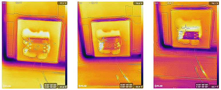
Figure 9. Assembly heating at −17.8°, −1.1° and 15.6°C (0°, 30°, and 60°F) with 3 V applied.
Heating performance of the assembly with flat heat sink shows temperatures ranging from −1.8°C (28.8°F) to 80.6°C (177.0°F). The heating results for this assembly always exhibit a positive trend with increasing voltage. At −17.8°C (0°F) temperature, heating temperatures range between −1.8°C (28.8°F) and 27.0°C (80.6°F). Observed values without applied voltage start at −3.0°C (26.6°F). At −1.1°C (30.0°F) temperature, results show values rising from 9.8°C (49.6°F) to 71.0°C (159.8°F) from 1 to 6 V respectively. At 15.6°C (60.0°F) temperature, values ranged from 21.4°C (70.5°F) to 80.6°C (177.0°F). Heat sink temperatures at this temperature exceeded 37.8°C (100.0°F) when 3 V was applied.
Temperature difference data in the heating mode indicates that heating performance behaves consistently despite thermal chamber temperatures, as shown in Figure 10. Detailed data is shown in Table 1. Higher thermal chamber temperatures lead to higher temperature differences with increasing power being applied. This was observed in both assemblies; however, the flat heat sink showed positive trends, while the large heat sink showed relatively constant temperature differences with increasing power. The temperature differences observed in the flat heat sink greatly exceeded the manufacturer stated maximum of 18.3°C (65.0°F), leading to failure at 7 W. The large heat sink assembly displayed a relatively constant difference of 18.3–21.1°C (65.0–70.0°F), even as power input increases.
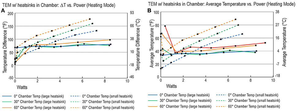
Figure 10. (A) ΔT vs. Watts and (B) average temperature vs. Watts in heating mode.
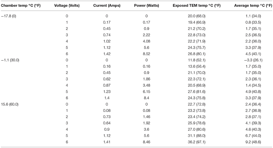
Table 1. Results of thermal testing (heating mode).
Thermal Chamber Testing Results: Cooling
Results indicate that cooling outputs are dependent on TEM assembly. The data for the assembly with a large heat sink indicated that at a 15.6°C (60.0°F) ambient temperature, cooling ranges from 22.0°C (71.6°F) to 7.8°C (46.1°F) when voltage is applied in 1 V increments. However, cooling does not occur linearly. The minimum temperature was observed when 4 V was applied to the large heat sink, while 5 and 6 V values were slightly higher, at 12.1°C (53.7°F) and 9.7°C (49.5°F) respectively. Cooling performance was more effective at 15.6°C (60.0°F). Temperatures observed at 1–3 V were higher than 15.6°C (60.0°F) temperature (due to testing room temperature), but lowered significantly when higher voltages were applied. At 32.2°C (90.0°F) temperature, TEM performance is relatively uniform. Measured temperatures ranged from 14.0°C (57.2°F) to 19.3°C (66.8°F).
The flat heat sink assembly showed results ranging from 6.3°C (43.3°F) to 34.4°C (93.9°F). Observed temperatures were lower when operated at 15.6°C (60.0°F), and remained below the ambient temperature up to 4 V. Temperatures observed at 32.2°C (90.0°F) ranged from 22.7°C (72.8°F) to 34.4°C (93.9°F). Temperatures remained below the ambient temperature up to 5 V, but temperatures observed would not provide adequate cooling for occupant thermal comfort.
Results for the cooling mode indicates that higher temperature differences arise as power inputs increases within the assemblies, as seen in Figure 11. This was observed in both assemblies; however, the flat heat sink showed positive trends, while the large sink showed a slightly negative trend or constant temperature difference trend. Table 2 shows detailed results.
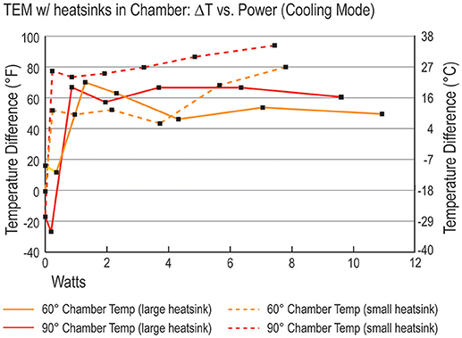
Figure 11. ΔT vs. Watts in cooling mode.
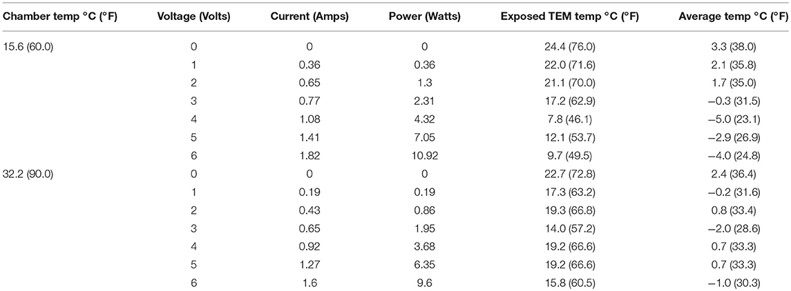
Table 2. Results of thermal testing (cooling mode).
Performance
The overall efficiency of the investigated assemblies was captured by the coefficient of performance (COP) in both heating and cooling modes. The COP is the ratio of the heat flux caused by the TEM (Q) over the electrical input power (P). Hence the COP represents the output (heat) and the input (electrical power). The input power is the product of voltage and current recorded from the power supply, while the heat flux Q was calculated from the difference between heatsink and environmental temperature, divided by the thermal resistance R of the heatsink. The R was calculated to be 0.22°C/W (0.396°F/W) based on the area, thickness, and total number of cooling fins on the heatsink. Thus, the complete formula for the COP is:
The COP values were calculated assuming Troom = 22.2°C (72.0°F). The results are shown in Figure 12. The COP values can be negative when ΔT is large. This is because heat naturally diffuses from hot to cold, sometimes termed the “passive” flux, while the TEM is trying to push a heat flux in the opposite direction, from cold to hot, termed “active” flux. The heat flux produced by the TEM is proportional to the input power, while the opposing natural diffusion is proportional to ΔT. When input power is low and ΔT is high, the active flux is smaller than the passive component, and the total in the numerator of the COP formula is negative. As input power increases, the active flux overtakes the passive and a net COP ranging from 1 to 3 is observed, meaning that the TEM pushes 1–3 Watts of heat for every Watt of input. Under smaller ΔT values, the COP can exceed 5; however, practical applications require as much heat flux as possible and at the largest input powers tested (8–10 Watts), the COP is only slightly higher, reaching values of 5–6. These COPs are reasonably high and comparable to smaller conventional HVAC systems, but here we have the added advantage of size, noise, and reliability. Furthermore, despite the TEM having relatively low efficiency in power generation mode (when extracting electricity from a temperature difference) of about 5–10%, the COP in heating and cooling modes can easily exceed 1.
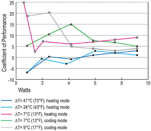
Figure 12. Coefficient of performance.
Conclusion
This article discusses application of TE materials in exterior building enclosures to create active, energy-generating facade systems. These novel facade systems could be used for localized heating and cooling. In this study, we designed and developed two prototypes, which were tested in ambient and thermally controlled conditions. We evaluated both heating and cooling modes for a variety of environmental conditions (temperature ranges). Thermal imagining was used to measure temperature outputs of the facade-integrated TE materials.
The results show that TE materials operate at effective heating and cooling temperatures, even when exposed to variable exterior temperatures, represented by the thermal chamber. They are most effective when paired with a larger heat sink, especially for cooling. Results also show that TEMs, when integrated into facade prototypes, operate effectively in heating and cooling modes.
Facade-integrated TE materials operating without a heat sink or with a small heat sink are inefficient or ineffective. Without a means to transport and dissipate heat, TEMs overheat due to the thermal transport involved at the molecular level. Thermal bridging may also contribute to high cold side temperatures.
Results of this study show promising opportunities for integrating TE materials in facade systems. There are many potential benefits associated with these novel facade systems, relating to energy usage, occupants' comfort and operation of buildings. Localized radiant heating and cooling, which can be controlled by occupants, could provide improved thermal comfort conditions. The mechanical equipment required for HVAC can be reduced, leading to lower maintenance requirements and operational cost reductions. TE materials can be integrated and paired with radiant panels to cause less disruption to interior spaces than traditional HVAC equipment.
Next steps for this research will include investigation of thermal transport in several different exterior wall types (computational and experimental), used for commercial and residential applications.
Author Contributions
AA: Primary writer of the submitted manuscript, co-Pi on the research project; ZA: Secondary writer of the submitted manuscript, co-PI on the research project; CC: Data collecting and charts, research assistant; DB: Data collecting, experimental set up, development of models for prototypes; MU: Literature review on TE materials.
Conflict of Interest Statement
The authors declare that the research was conducted in the absence of any commercial or financial relationships that could be construed as a potential conflict of interest.
References
Aksamija, A. (2013). Sustainable Facades: Design Methods for High-Performance Building Envelopes. New York, NY: John Wiley and Sons.
Bell, L. (2008). Cooling, heating, generating power, and recovering waste heat with thermoelectric systems. Science 321, 1457–1461. doi: 10.1126/science.1158899
Department of Energy (2011). Building Energy Data Book 2011. Available online at: https://openei.org/doe-opendata/dataset/buildings-energy-data-book (Accessed March 30, 2017).
Ibanez-Puy, M., Sacristan Fernandez, J., Martin-Gomez, C., and Vidaurre-Arbizu, M. (2015). Development and construction of a thermoelectric active facade module. J. Facade Design Eng. 3, 15–25. doi: 10.3233/FDE-150025
Kraemer, D., Poudel, B., Feng, H., Caylor, J., Yu, B., Yan, X., et al. (2011). High-performance flat-panel solar thermoelectric generators with high thermal concentration. Nat. Mater. 10, 532–538. doi: 10.1038/nmat3013t
Liu, Z. B., Zhang, L., Gong, G., and Luo, Y. (2015). Evaluation of a prototype active solar thermoelectric radiant wall system in winter conditions. Appl. Therm. Eng. 89, 36–43. doi: 10.1016/j.applthermaleng.2015.05.076
Montecucco, A., Buckle, J. R., and Knox, A. R. (2012). Solution to the 1-D unsteady heat conduction equation with internal Joule heat generation for thermoelectric devices. Appl. Therm. Eng. 35, 177–184. doi: 10.1016/j.applthermaleng.2011.10.026
Schonecker, A., Kraaijvelda, B., van Til, A., Bottgerb, A., Brinks, P., Huijben, M., et al. (2015). Cost efficient manufacturing of silicide thermoelectric materials and modules using RGS technique. Mater. Today 2, 538–547. doi: 10.1016/j.matpr.2015.05.074
Seetawan, T., Singsoog, K., and Srichai, K. (2014). “Thermoelectric energy conversion of p-Ca3Co4O9/n-CaMnO3 module,” in Proceedings of the 6th International Conference on Applied Energy (Taipei), 2–5.
Shen, L., Xiao, F., Chen, H., and Wang, S. (2013). Investigation of a novel thermoelectric radiant air-conditioning system. Energy Build. 59, 123–132. doi: 10.1016/j.enbuild.2012.12.041
Twaha, S., Zhu, J., Yan, Y., and Li, B. (2016). A comprehensive review of thermoelectric technology: materials, applications, modelling and performance improvement. Renew. Sust. Energ. Rev. 65, 698–726. doi: 10.1016/j.rser.2016.07.034
Yilmazoglu, M. (2016). Experimental and numerical investigation of a prototype thermoelectric heating and cooling unit. Energy Build. 113, 51–60. doi: 10.1016/j.enbuild.2015.12.046
Zhao, D., and Tan, G. (2014). A review of thermoelectric cooling: materials, modeling and applications. Appl. Therm. Eng. 66, 15–24. doi: 10.1016/j.applthermaleng.2014.01.074
Zheng, X. F., Liu, C. X., Yan, Y. Y., and Wang, Q. (2014). A review of thermoelectrics research - recent developments and potentials for sustainable and renewable energy applications. Renew. Sust. Energy 32, 486–503. doi: 10.1016/j.rser.2013.12.053
Keywords: thermoelectric materials, facade systems, heating and cooling, high-performance buildings, experimental study, intelligent facades
Citation: Aksamija A, Aksamija Z, Counihan C, Brown D and Upadhyaya M (2019) Experimental Study of Operating Conditions and Integration of Thermoelectric Materials in Facade Systems. Front. Energy Res. 7:6. doi: 10.3389/fenrg.2019.00006
Received: 27 September 2018; Accepted: 18 January 2019;
Published: 07 February 2019.
Edited by:
David W. Yarbrough, R & D Services, Inc., United StatesReviewed by:
Xiaofeng Guo, ESIEE Paris, FranceDimitrios Kraniotis, OsloMet–Oslo Metropolitan University, Norway
Copyright © 2019 Aksamija, Aksamija, Counihan, Brown and Upadhyaya. This is an open-access article distributed under the terms of the Creative Commons Attribution License (CC BY). The use, distribution or reproduction in other forums is permitted, provided the original author(s) and the copyright owner(s) are credited and that the original publication in this journal is cited, in accordance with accepted academic practice. No use, distribution or reproduction is permitted which does not comply with these terms.
*Correspondence: Ajla Aksamija, YWFrc2FtaWphQHVtYXNzLmVkdQ==