 Zhanwei Liu
 Yanwei Yue2
 Luchao She
 Guangming Fan
- 1Fundamental Science on Nuclear and Simulation Technology Laboratory, Harbin Engineering University, Harbin, China
- 2Research and Development Center, China Nuclear Power Engineering Co., Ltd, Beijing, China
In this study, single-phase heat transfer enhancement in internally finned tubes is investigated numerically. The influence of fin number, helix angle, fin height, fin width, and shape on the flow and heat transfer characteristics is studied. The research results indicate that the resistance coefficient and Nusselt number both increase with the increment of these parameters, among which the helix angle has the largest impact on the heat transfer enhancement. In addition, the shape of fins also has a small effect on the flow and heat transfer, and the heat transfer effect of triangular fins is the best.
Introduction
Single-phase convection heat transfer enhancement techniques are widely applied in industries such as petroleum, chemical engineering, etc. In recent years, its applications in the field of nuclear technology has been an engaging research area of heat transfer augmentation. In the advanced nuclear power plant like AP1000, HPR1000 and CAP1400, passive residual heat removal system (PRHR) (Schulz, 2006; Xing et al., 2016; Zheng et al., 2016) can discharge residual heat through single-phase convection heat transfer under normal condition, therefore enhancement of its heat transfer efficiency is of great significance to the safe operation of nuclear reactors.
In order to strengthen the single-phase convection heat transfer technology, many heat exchanger elements have been developed, the internally finned tube is one of them. Ji et al. (2015) found that their thermal-hydraulic performance is the best among all enhanced tubes through a comprehensive literature review. Much work has been done to investigate the heat transfer characteristics of internally finned tubes in condensation (Seo and Kim, 2000; Kim et al., 2002; Yu et al., 2002; Yun et al., 2002) and evaporation (Chamra and Webb, 1996; Chamra et al., 2004, 2005; Chamra and Mago, 2006), but the heat transfer characteristics of single-phase in these tubes are not thoroughly understood for lack of research. The internally finned tube has high requirements for water quality, and the working fluid is required to be clean enough with almost no impurities, otherwise they may affect the heat transfer performance. Compared with other heat exchanger elements, the tremendous advantage of internally finned tubes is that its heat transfer effect is greater than the increase of pressure drop. Generally, this effect can be seen in turbulent state, but neither the enhancement of heat transfer nor that of pressure drop is obvious in laminar state, thus they are recommended to be used in turbulent flow (Al-Fahed et al., 1999; Copetti et al., 2004).
Previous experimental studies have been carried out on single-phase flow of different working media to investigate the influence of different geometrical sizes (fin height, fin width, helix angle, diameter, fin number) on the heat transfer characteristics. Wang et al. (1996) experimentally tested seven internally finned tubes with different geometric sizes such as diameter, fin height, helix angle and fin numbers, and established heat transfer and pressure drop correlations in a wide range of Reynold number. Han and Lee (2005) studied the single-phase heat transfer and flow characteristics of water in four internally finned tubes with different diameters, fin heights, helix angles and fin pitchs experimentally, and developed correlations for friction factor and heat transfer coefficients. Jensen and Vlakancic (1999) carried out experimental studies on turbulent flow in eight internally finned tubes with different geometrical parameters of helix angles, fin heights, fin numbers and fin widths, they obtained the correlations between friction coefficient and Nusselt number. Later Zdaniuk et al. (2008) determined and compared friction factors as well as heat transfer coefficients of eight internally finned tubes experimentally. Empirical correlations for one particular internally finned tubes was developed by Siddique and Alhazmy (2008) through experimental research. And a critical Reynolds number Recr was discovered by Li et al. (2007) through experimental study. Ji et al. (2011) measured the turbulent heat transfer and friction factors of sixteen internally finned tubes with various geometrical parameters including fin number, fin height, diameter, helix angle, and developed an equation for the heat transfer in the fully developed flow as an extension of the Gnielinski equation. Friction formula was also developed by Celen et al. (2013). Besides, Experimental studies of R134, R12 (Eiamsa-ard and Wongcharee, 2012) and the water-CuO nanofluid (Eiamsa-ard and Wongcharee, 2013) were also conducted.
Due to the limitations of manufacturing and experimental conditions, only a few tubes with specific geometrical parameters have been studied in previous experiment research, so it is difficult to obtain the detailed and comprehensive heat transfer characteristics in different tubes.
There are only a few numerical studies on the heat transfer characteristics of internally finned tubes. Agra et al. (2011) studied the heat transfer characteristics and pressure drop of five internally finned tubes in the turbulent state numerically, they compared their simulation results with the experimental data of Zdaniuk et al. (2008), and discovered that CFD predicted the experimental data more accurately than the Blasius equation. Their results also indicated that the internally finned tube has a higher heat transfer coefficient than the corrugated tube. Celen et al. (2014) studied the pressure drop in one internally finned tube with TiO2-water nanofluids numerically, and described the average and local values of temperature, pressure, and velocity distributions of the tube. Dastmalchi et al. (2017) investigated the characteristics of laminar oil flow in internally finned tubes with different fin heights and helical angles numerically. They concluded that there is an optimal height and an optimal helix angle which leads to the maximum performance of heat transfer.
The foregoing literatures indicate that a comprehensive study on the flow and heat transfer characteristics considering a wide range of parameters including fin number, helix angle, fin height, fin width and shape of fins remains to be conducted. Influence of geometric parameters on characteristics of heat transfer could be implemented with modern visualization techniques and computational fluid dynamics (CFD) tools. Therefore, the purpose of the study is to conduct a comprehensive numerical study on the factors affecting the heat transfer efficiency of the internally finned tubes.
Numerical Method and Procedure
Geometric Model
The fins are uniformly distributed in circumferential direction and along the axis with the same helix angle, so they are periodic in geometric structure. The rectangular fins studied have the diameter D = 20 mm, length L = 20 mm, fin number N = 30, the fin height e = 0.5 mm, the width s = 0.5 mm, the helix angle of 30°. The cross section is shown in Figure 1.
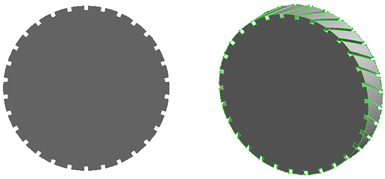
Figure 1. Schematic diagram of cross section of helix internal finned tube.
Using the periodicity of the internally finned tube and taking one pitch of the fully developed segment as the computational domain, the difficulty of grid generation is greatly reduced. The established model is shown in Figure 1.
Grid Generation and Boundary Conditions
In order to determine a proper grid for the numerical simulations, a grid independence study is carried out for the smooth and internally finned tubes. A section of circular tube with a diameter of 20 mm and a length of 20 mm is taken as the computing domain, and meshing is used to generate grids.
The mesh number chosen in this paper is the minimum of the mesh number that does not affect the simulation results. When the number of grids is lower than a certain value, the change of the number of grids will have an impact on the simulation results. The larger the number of grids, the closer to the stable result. When the number of grids is higher than a certain value, the encrypted grid will have no impact on the simulation results.
As shown in Figures 2A,B, the grid of smooth tube is made by independence verification. Grid quality measurement method is skewness, the value <0.7 is acceptable, so the grid generation is credible as most values are below 0.6.
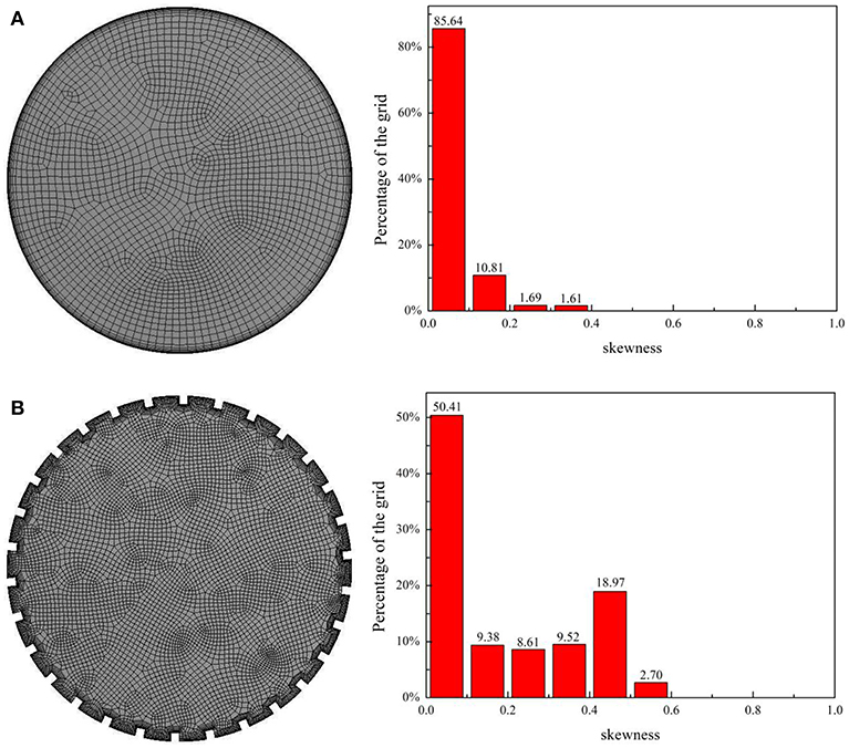
Figure 2. Grid distribution and volume grid quality of heat transfer tube. (A) Smooth tube. (B) Internally finned tube.
Realizable k-epsilon model satisfies the constraint conditions of Reynolds stress, so it can be consistent with the real turbulence at Reynolds stress. This is something neither the standard k-epsilon model nor the RNG k-epsilon model can do. The advantage of this feature in the calculation is that it can more accurately simulate the diffusion velocity of plane and circular jets. Meanwhile, in the calculation of rotating flow, boundary layer with directional pressure gradient and separation flow, the calculation results are more in line with the real situation.
The Realizable k-epsilon model is a newly emerging k-epsilon model, and although its performance has not been proven to be superior to the RNG k-epsilon model, studies on separated flow calculations and complex flow calculations with secondary flows show that the Realizable k-epsilon model is the most excellent turbulence model among all the models. Given the advantages of the Realizable k-epsilon model, this paper chooses this model for calculation.
We used the standard k − ε model in fluent to solve the turbulent kinetic energy equation and turbulent dissipation rate equation, then calculated the turbulent viscosity with the value of the sum, and finally obtained the solution.
The enhanced wall treatment is selected to obtain the detailed flow condition near the tube wall. In the two-layer zone model, the near-wall flow can only be divided into two regions, namely the region affected by viscosity and complete turbulence. The two regions are distinguished by Rey based on the distance y to the wall.
The optimal grid division requires that the first grid is at the position y+ =1. It is acceptable as long as it is in the bottom viscous layer even a little bit bigger, like y+ =4~5.
After the grid is read into FLUENT, the parameters and boundary conditions are set as follows: single phase water with constant physical properties, the constant heat flow boundary condition and the given heat flux is q = 1,00,000 W/m2, the countercurrent volume temperature is set as 300 K, the coupling solution of pressure and velocity is SIMPLEC algorithm, and the momentum and energy equations are solved by the second-order upwind scheme.
Verification of the Numerical Procedure
Based on the pressure drop value per unit length obtained, the average f can be calculated using Darcy formula:
Based on the difference between the average wall temperature and the average fluid temperature, the average Nusselt number can be calculated:
For forced convection heat transfer in smooth circular tubes, the resistance coefficient can be calculated using the Filonenko formula (Filonenko, 1954):
The nussel number can be calculated according to the Gnielinski (Gnielinski, 1975) formula:
The selected grid scheme is used for verification. The comparison results with the classical experimental formula are shown in Figures 3A,B. The calculated values of f and Nu are compared with the values of Filonenko formula (Filonenko, 1954) and Gnielinski formula (Gnielinski, 1975), respectively. It can be seen that the calculated value of the resistance coefficient and the Nusselt number are in good agreement with the theoretical value. The maximum error between the calculated value and the theoretical value of the resistance coefficient is 6.25%, most of which are within 3%.The maximum error between the calculated value and the theoretical value of nusserl number is 11.2%, most of which is about 5%. The maximum error occurs in the lower Reynolds number region. The results show that the application of periodic boundary conditions and the established calculation model are correct and can accurately simulate the turbulent flow and heat transfer in the tube.
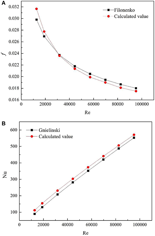
Figure 3. Comparison between the calculated value and the theoretical value in smooth tubes. (A) f. (B) Nu.
Results and Discussion
In this section, the effect of fin number, fin height, fin width, helix angle and the shape of fins on the heat transfer characteristics of internally finned tube are studied.
Effect of Fin Number
Figure 4 shows the effect of the fin number on the Nu and f at different helix angles. The fin height and fin width are fixed at 0.5 mm, and the fin number are 15, 30, and 45, respectively. It can be seen that the Nu and f both increase with the augment of the fin number and helix angle.
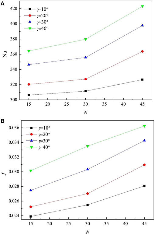
Figure 4. The effect of the fin number on the Nu and f at different helix angles. (A) Nu. (B) f.
Table 1 shows the variation of the increment of heat exchange area with fin number and the helix angle. Here the increment of heat exchange area is defined as:
It can be seen that the rate at which Nu increases is bigger than the increase speed of heat exchange area and f, which indicates that the enhancement effect of heat transfer is greater than the increase of resistance and heat transfer area.
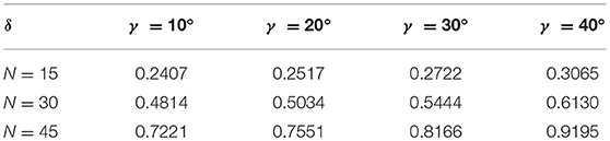
Table 1. Increment of heat exchange area under different fin number and helix angle.
Figure 5 shows the velocity cloud diagram and temperature cloud diagram of internally finned tubes with fin number of 15, 30, and 45. It can be seen that at the sharp corners of the windward side, the wall is the most strongly impacted by the fluid, the boundary layer is the thinnest, and the velocity gradient is the largest, so a great shear stress is generated which means that there is a great loss of energy. Meanwhile, the corresponding fluid temperature is the lowest, and the heat transfer convection is the strongest. As the fin number increases, the number of sharp corners increase, resulting in an increase in both f and Nu. Along with the increase of fin number, the intercostal region decreases accordingly, the fluid viscosity of the intercostal channel increases, which reduces the fluid velocity of fin root and surface, thickens boundary layer, and inhibits the heat transfer.
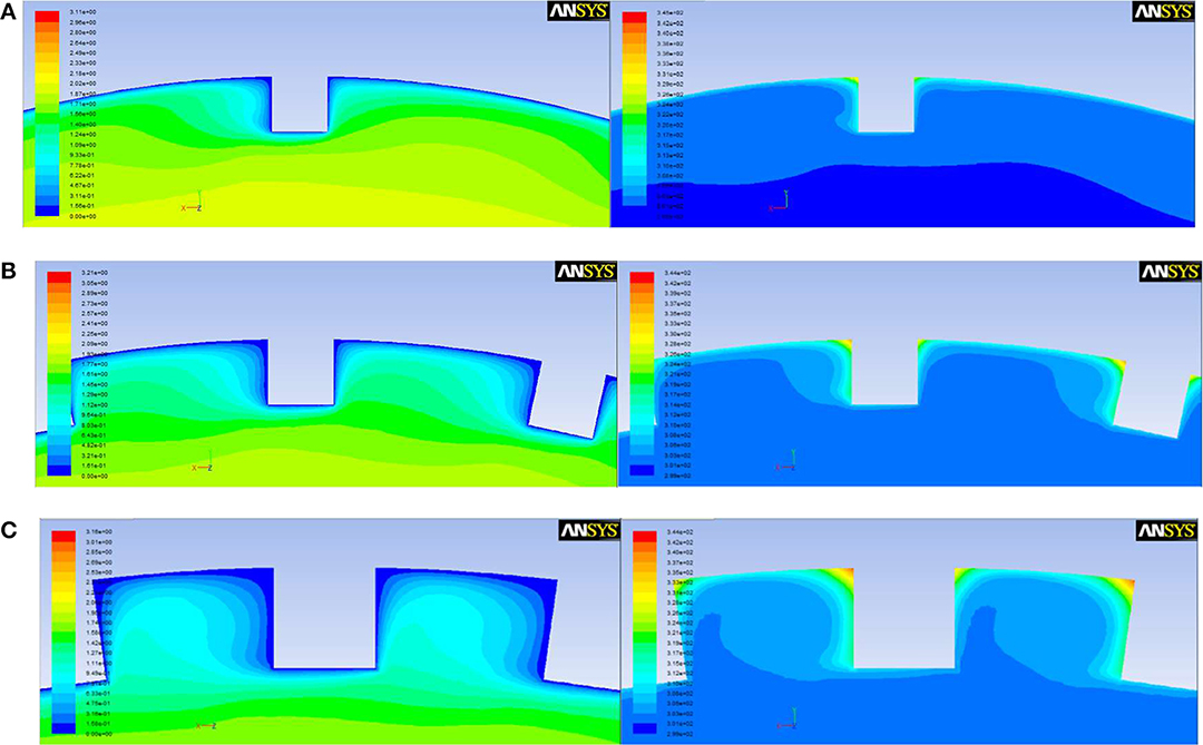
Figure 5. The velocity cloud diagram and temperature cloud diagram with different fin numbers. (A) N = 15. (B) N = 30. (C) N = 45.
Effect of Fin Height
Figure 6 shows the changes of Nu and f with the fin height under different helix angles. The fin number is 30, the fixed fin width is 0.5 mm, and the fin height is 0.3, 0.5, 0.7, and 0.9 mm, respectively (the dimensionless fin height H changes from 0.03 mm to 0.09 mm). It can be seen that the Nu and f both increase with the augment of the fin height, as it not only increases the heat transfer area on both fin sides, but also promotes the interactions between the fin top. When the helix angle is >20°, Nu and f grow significantly compared with small helix angle such as 10 and 20° with the increase of fin height, which indicates that the helix angle plays an important role in the heat transfer.
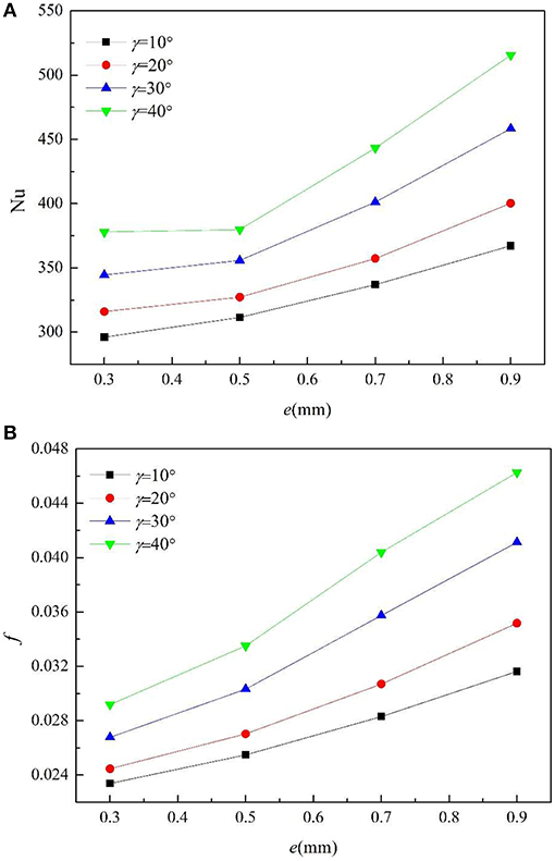
Figure 6. The effect of the fin height on the Nu and f at different helix angles. (A) Nu. (B) f.
Table 2 shows the changes of heat exchange area with the fin height and helix angle. Nu and f both increase with fin height, because the higher the fin height, the greater the disturbance to the fluid near the wall surface. Therefore, the heat transfer coefficient is enhanced and the resistance coefficient is increased. Increasing the spiral angle will further enhance the heat transfer and the resistance.
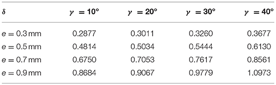
Table 2. Increment of heat exchange area under different fin height and helix angle.
The increment of the fin height increases the interaction between fins and fluid, resulting in rapid increase in f and Nu.
Effect of Fin Width
Generally, the fin width has a complex effect on the flow and heat transfer in internally finned tubes. The increment of fin width does not increase the heat transfer area, but it will cause the change of the size of the intercostal passage. Due to the limitations of time and conditions, only the effect of fin width within a small range between 0.5 and 0.9 mm is studied under the condition that the number of fins is 30.
Figure 7 shows the changes of Nu and f with the fin width. As we can see, with the increment of the fin width, Nu and f both increase slowly.
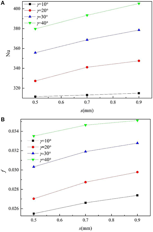
Figure 7. The effect of the fin width on the Nu and f at different helix angles. (A) Nu. (B) f.
Figure 8 shows the velocity cloud and temperature cloud when the fin width is 0.5, 0.7, and 0.9 mm, respectively. It can be seen that the increase of fin width means that the area of the fin top increases, equivalently the area in contact with the fluid is larger, and fins are more impacted by the fluid, so heat transfer and friction resistance are both enhanced.
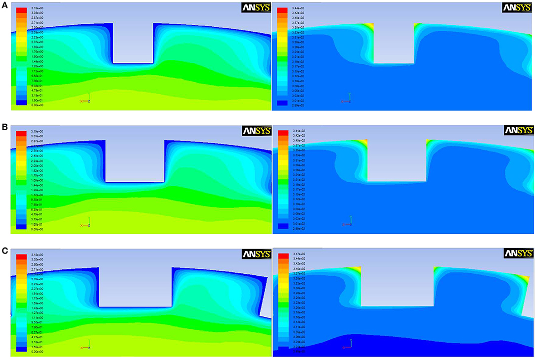
Figure 8. The cloud picture of velocity and temperature with different fin width. (A) s = 0.5 mm. (B) s = 0.7 mm. (C) s = 0.9 mm.
Similar to the increase of fin number, as fin width increases, the intercostal region decreases accordingly, the viscous effect of the fin side and the inner wall against the intercostal fluid also increases, which reduces the flow rate in the intercostal region, thickens the boundary layer and suppresses the heat transfer between the fin root and the wall, thus causes the decrease of Nu and f. The opposite effect of the two factors makes Nu and the f changed slowly.
Effect of Helix Angle
Figure 9 shows the changes of f and Nu with the helix angle under different fin numbers to study the effect of helix angle. The fixed fin width is 0.5 mm, and the fixed fin height is 0.5 mm. The reason that we chose the spiral angle of 10 to 40° is that the spiral Angle is usually 10 to 45° in industrial applications, so we chose the most representative parameters for numerical simulation.
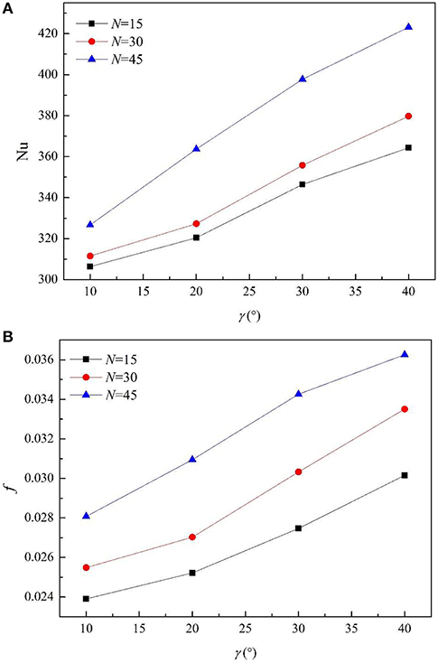
Figure 9. The effect of helix angle on the Nu and f at different fin numbers. (A) Nu. (B) f.
As we can see, Nu and f both increase with helix angle dramatically. The bigger the helix angle is, not only the area of the fin exposed to the incoming flow windward increases, but also the change of fluid flow direction increases, that is, the greater the obstruction to the incoming flow. Therefore, the incoming flow has a stronger impact on the windward side of the fin, and f and Nu both increase.
Figure 10 shows the velocity vector of intercostal area. The arrows in the bottom parts of Figures 10A–C point to left bottom, while the arrows in the bottom part of Figure 10D point to left, this is because the larger the spiral angle is, the more the fluid near the wall is affected by the spiral angle, and the greater the included Angle with the mainstream is. So it tends to the horizontal.
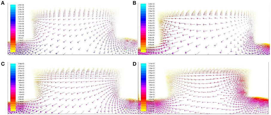
Figure 10. The velocity vector of intercostal area with different helix angle. (A) 10°. (B) 20°. (C) 30°. (D) 40°.
Effect of Fin Shape
Figure 11 shows the changes of f and Nu with three fin shapes, as shown in the picture, the average f in rectangular fins is the highest and that of triangular fins is the lowest, and that of circular fins is between them. The maximum difference between rectangular and triangular fins is 9.85%, and with the increase of Re, the difference between f gradually decreases. As can be seen from Figure 11, the Nu of rectangular and triangular fins is basically the same, and the triangular fin is slightly larger. With the increase of Re, the difference of Nu between the circular fin and the other two kinds of fins gradually increases, and the maximum difference is 5.9%.
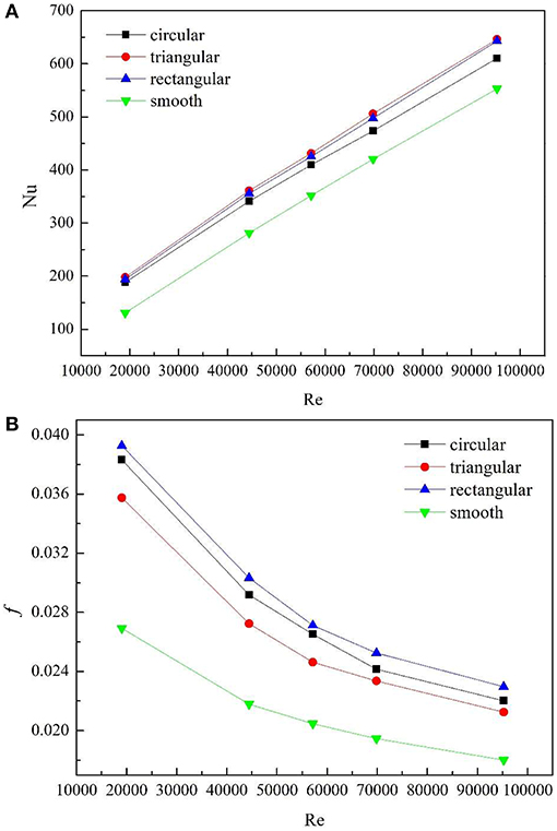
Figure 11. Comparison between three fin shapes. (A) Nu. (B) f.
Table 3 compares the increment in heat transfer area, Nu and f caused by the three types of fins in turbulent state. It can be seen from the table that the heat transfer area of rectangular fins increases the most, while that of triangular fins increases the least, and the difference of the three types of fins lies in the shape of fin top. For rectangular fins and triangular fins, the top has a sharp angle, while the top of circular fins is a smooth surface, which lead to different flow and heat transfer characteristics.
Table 3. Comparison of parameters of three kinds of fin tubes.
Figure 12 shows the velocity field cloud and temperature field cloud of rectangular fin, triangular fin and circular fin respectively when the Re is 70000 and ρ is 100000. As we can see, the sharp angles of rectangular fins and triangular fins are impacted by the incoming flow, which greatly enhance the heat transfer in the region. Therefore, the average Nu is higher than that of circular fins, and as the Re increases, the interaction between the fluid and the sharp angle of rectangular fins and triangular fins becomes more intense. It is noted that the Nu of the triangular fins is slightly higher than that of the rectangular fins, because compared with rectangular fins, the intercostal passage between adjacent fins of the tube in the triangular fins is larger, and the larger intercostal area could pump more turbulence into the root area of the fin, thinning the boundary layer, thus enhancing heat transfer. The heat transfer area of the triangular fins increases the least, f increases the least and Nu increases the most, so the heat transfer performance is the best.
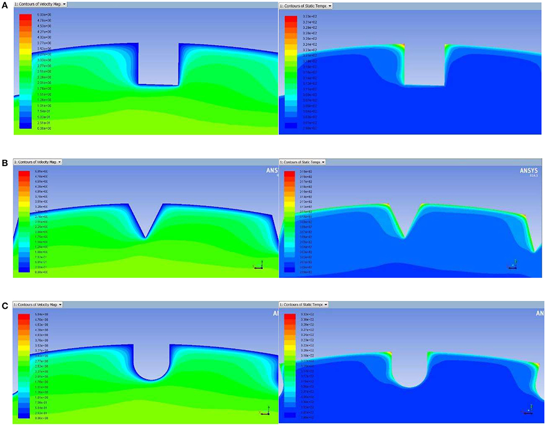
Figure 12. The velocity field cloud and temperature field cloud of different fin shapes. (A) Rectangular fins. (B) Triangular fins. (C) Circular fins.
Conclusion
In this study, FLUENT software and periodic boundary conditions are used to simulate the flow and heat transfer in internally finned tubes comprehensively, and to study the influence of various geometric parameters. The parameters are fin number (15–45), fin height (0.3–0.9 mm), fin width (0.5–0.9 mm), helix angle (10–40°) and the operating condition is Re = 44430. Meanwhile, the influence of the fin shapes on the heat transfer and the influencing mechanism are also explored. The conclusions are as follows:
(1) The geometrical parameters of internally finned tubes affect the characteristics of flow and heat transfer, and Nu and the f both increase with them.
(2) Compared with fin number, fin height has a greater influence on the flow and heat transfer of internally finned tubes.
(3) Fin width has no significant effect on the flow and heat transfer. The Nu and f both change slowly with fin width.
(4) Among all the geometrical parameters, the helix angle has the largest influence on the flow and heat transfer in the internally finned tube.
(5) The shape of the fin has no significant influence on the flow and heat transfer characteristics. The maximum difference of drag coefficient between the three finned shapes was within 10%, and the difference of nussel number was within 6%. If other parameters are the same, the heat transfer performance of the triangular fin is the best.
Data Availability
The raw data supporting the conclusions of this manuscript will be made available by the authors, without undue reservation, to any qualified researcher.
Author Contributions
In the course of the completion of this thesis, all authors have substantial contributions to design of the work, and the contribution of YY is equivalent to that of the first author. GF provided the research direction of the subject, all authors worked together to define the methodology and procedures. LS built the geometric model. ZL carried out numerical simulation and obtained, collated, and analyzed the data. GF and LS also provided guidance and assistance in the process. ZL wrote the first draft of the paper and corrected it by GF and LS. YY provided important guidance in the process, and his contribution is equivalent to that of the first author. All authors approved the final version to be published. All authors agreed to be responsible for all aspects of the work.
Funding
This work was supported by National Natural Science Foundation of China (11875117).
Conflict of Interest Statement
The authors declare that the research was conducted in the absence of any commercial or financial relationships that could be construed as a potential conflict of interest.
Acknowledgments
ZL would like to extend his sincere gratitude to his supervisor GF for his instructive advice and guidance on his thesis. ZL would also like to thank YY for his important guidance in this process, whose contribution is equivalent to that of the first author.
References
Agra, O., Demir, H., Atayilmaz, S., Kantas, F., and Dalkiliç, A. S. (2011). Numerical investigation of heat transfer and pressure drop in enhanced tubes. Int. Commun. Heat Mass Transf. 38, 1384–1391. doi: 10.1016/j.icheatmasstransfer.2011.07.013
Al-Fahed, S., Chamra, L., and Chakroun, W. (1999). Pressure drop and heat transfer comparison for both microfin tube and twisted-tape inserts in laminar flow. Exp. Thermal. Fluid Sci. 18, 323–333. doi: 10.1016/S0894-1777(98)10037-7
Celen, A., Dalkilic, A. S., and Wongwises, S. (2013). Experimental analysis of the single phase pressure drop characteristics of smooth and microfin tubes. Int. Commun. Heat Mass Transf. 46, 58–66. doi: 10.1016/j.icheatmasstransfer.2013.05.010
Celen, A., Kayaci, N., Cebi, A., Demir, H., Dalkiliç, A. S., and Wongwises, S. (2014). Numerical investigation for the calculation of TiO2ewater nanofluids' pressure drop in plain and enhanced tubes. Int. Commun. Heat Mass Transf. 53, 98–108. doi: 10.1016/j.icheatmasstransfer.2014.02.022
Chamra, L. M., and Mago, P. J. (2006). Modeling of condensation heat transfer of refrigerant mixture in micro-fin tubes. Int. J. Heat Mass Transf. 49, 1915–1921. doi: 10.1016/j.ijheatmasstransfer.2005.11.006
Chamra, L. M., Mago, P. J., Tan, M. O., and Kung, C. C. (2005). Modeling of condensation heat transfer of pure refrigerants in micro-fin tubes. Int. J. Heat Mass Transf. 48, 1293–1302. doi: 10.1016/j.ijheatmasstransfer.2004.10.005
Chamra, L. M., Tan, M. O., and Kung, C. C. (2004). Evaluation of existing condensation heat transfer models in horizontal micro-fin tubes. Exp. Thermal Fluid Sci. 28, 617–628. doi: 10.1016/j.expthermflusci.2003.10.006
Chamra, L. M., and Webb, R. L. (1996). Advanced micro-fin tubes for condensation. Int. J. Heat Mass Transf. 39, 1839–1846. doi: 10.1016/0017-9310(95)00275-8
Copetti, J. B., Macagnan, M. H., de Souza, D., and Oliveski, R. D. C. (2004). Experiments with micro-fin tube in single phase. Int. J. Refrig. 27, 876–883. doi: 10.1016/j.ijrefrig.2004.04.015
Dastmalchi, M., Arefmanesh, A., and Sheikhzadeh, G. A. (2017). Sheikhzadeh.Numerical investigation of heat transfer and pressure drop of heat transfer oil in smooth and micro-finned tubes. Int. J. Therm. Sci. 121, 294–304. doi: 10.1016/j.ijthermalsci.2017.07.027
Eiamsa-ard, S., and Wongcharee, K. (2012). Single-phase heat transfer of CuO/water nanofluids in micro-fin tube equipped with dual twisted-tapes. Int. Commun. Heat Mass Transf. 39, 1453–1459. doi: 10.1016/j.icheatmasstransfer.2012.08.007
Eiamsa-ard, S., and Wongcharee, K. (2013). Heat transfer characteristics in micro-fin tube equipped with double twisted tapes: effect of twisted tape and micro-fin tube arrangements. J. Hydrodyn. Ser. B 25, 205–214. doi: 10.1016/S1001-6058(13)60355-8
Gnielinski, V. (1975). New Equations for Heat and Mass Transfer in the Turbulent Flow in Pipes and Channels. NASA STI/Recon Technical Report A, 75.
Han, D. H., and Lee, K. J. (2005). Single-phase heat transfer and flow characteristics of microfin tubes. Appl. Therm. Eng. 25, 1657–1669. doi: 10.1016/j.applthermaleng.2004.10.015
Jensen, M.K., and Vlakancic, A. (1999). Experimental investigation of turbulent heat transfer and fluid flow in internally finned tubes. Int. J. Heat Mass Transf. 42, 1343–1351. doi: 10.1016/S0017-9310(98)00243-9
Ji, W. T., Jacobi, A. M., He, Y. L., and Tao, W. Q. (2015). Summary and evaluation on single-phase heat transfer enhancement techniques of liquid laminar and turbulent tube flow. Int. J. Heat Mass Transf. 88, 735–754. doi: 10.1016/j.ijheatmasstransfer.2015.04.008
Ji, W. T., Zhang, D. C., He, Y. L., and Tao, W. Q. (2011). Prediction of fully developed turbulent heat transfer of internal helically ribbed tubes-an extension of Gnielinski equation. Int. J. Heat Mass Transf. 55, 1375–1384. doi: 10.1016/j.ijheatmasstransfer.2011.08.028
Kim, Y., Seo, K., and Chung, J. T. (2002). Evaporation heat transfer characteristics of R-410A in 7 and 9.52 mm smooth/micro-fin tubes. Int. J. Refriger. 25, 716–730. doi: 10.1016/S0140-7007(01)00070-6
Li, X. W., Meng, J. A., and Li, Z. X. (2007). Experimental study of single-phase pressure drop and heat transfer in a micro-fin tube. Exp. Therm. Fluid Sci. 32, 641–648. doi: 10.1016/j.expthermflusci.2007.08.005
Schulz, T. L. (2006). Westinghouse AP1000 advanced passive plant. Nuclear Eng. Design. 236, 1547–1557. doi: 10.1016/j.nucengdes.2006.03.049
Seo, K., and Kim, Y. (2000). Evaporation heat transfer and pressure drop of R-22 in 7 and 9.52 mm smooth/micro-fin tubes. Int. J. Heat Mass Transf. 43, 2869–2882. doi: 10.1016/S0017-9310(99)00338-5
Siddique, M., and Alhazmy, M. (2008). Experimental study of turbulent single-phase flow and heat transfer inside a micro-finned tube. Int. J. Refrig. 31, 234–241. doi: 10.1016/j.ijrefrig.2007.06.005
Wang, C. C., Chiou, C., and Lu, D. C. (1996). Single-phase heat transfer and flow friction correlations for microfin tubes. Int. J. Heat Fluid Flow 17, 500–508. doi: 10.1016/0142-727X(96)00048-3
Xing, J., Song, D., and Wu, Y. (2016). HPR 1000:advanced pressurized water reactor with active and passive safety. Engineering 2, 83–91. doi: 10.1016/J.ENG.2016.01.017
Yu, M., Lin, T., and Tseng, C. (2002). Heat transfer and flow pattern during two-phase flow boiling of R-134a in horizontal smooth and microfin tubes. Int. J. Refriger. 25, 789–798. doi: 10.1016/S0140-7007(01)00075-5
Yun, R., Kim, Y., Seo, K., and Kim, H. Y. (2002). A generalized correlation for evaporation heat transfer of refrigerants in micro-fin tubes. Int. J. Heat Mass Transf. 45, 2003–2010. doi: 10.1016/S0017-9310(01)00321-0
Zdaniuk, G. J., Chamra, L. M., and Mago, P. J. (2008). Experimental determination of heat transfer and friction in helically-finned tubes. Exp. Thermal Fluid Sci. 32, 761–775. doi: 10.1016/j.expthermflusci.2007.09.006
Zheng, M., Yan, J., Shentu, J., Tian, L., Wang, X., Qiu, Z., et al. (2016). The general design and technology innovations of CAP1400. Engineering 2, 101–106. doi: 10.1016/J.ENG.2016.01.018
Nomenclature

Keywords: internally finned tube, heat transfer enhancement, numerical simulation, single -phase flow, heat transfer coefficient
Citation: Liu Z, Yue Y, She L and Fan G (2019) Numerical Analysis of Turbulent Flow and Heat Transfer in Internally Finned Tubes. Front. Energy Res. 7:64. doi: 10.3389/fenrg.2019.00064
Received: 30 April 2019; Accepted: 02 July 2019;
Published: 18 July 2019.
Edited by:
Jun Wang, University of Wisconsin-Madison, United StatesReviewed by:
Han Bao, Idaho National Laboratory (DOE), United StatesZhitong Bai, University of Michigan, United States
Copyright © 2019 Liu, Yue, She and Fan. This is an open-access article distributed under the terms of the Creative Commons Attribution License (CC BY). The use, distribution or reproduction in other forums is permitted, provided the original author(s) and the copyright owner(s) are credited and that the original publication in this journal is cited, in accordance with accepted academic practice. No use, distribution or reproduction is permitted which does not comply with these terms.
*Correspondence: Guangming Fan, ZmFuZ3VhbmdtaW5nMDA3QGhvdG1haWwuY29t