 Vasiliki-Eleni Kralli
 Nicolaos Theodossiou
 Theophanis Karambas
- Division of Hydraulics and Environmental Engineering, Department of Civil Engineering, Aristotle University of Thessaloniki, Thessaloniki, Greece
The European Union, in its Framework Strategy for A Resilient Energy Union, as described in the “Clean Energy for all Europeans” package of measures, marked its energy priorities for transition to a low-carbon, secure and competitive economy. Following this direction, the paper deals with the exploitation of one of the most significant and extensively available energy sources, that of nearshore waves. More specifically the paper emphasizes in the optimal design of Overtopping Breakwater for Energy Conversion systems, known as OBREC, using a novel and very effective, meta-heuristic optimization technique, the Harmony Search Algorithm. The proposed methodology is based on the combined application of wave propagation equations that simulate the compound wave field near coastal structures where the waves are subjected to the combined effects of shoaling, refraction, diffraction, reflection—total and partial—and breaking, with an optimization algorithm, aiming at the identification of the optimal dimensions of an OBREC reservoir. In order to demonstrate the effectiveness of the methodology, the port of Heraklion in the island of Crete in Greece, is used as a case study. The results of the application are very promising and strongly support the statement that the proposed methodology provides a new concept in the design of OBREC systems.
Introduction
The excessive use of conventional energy resources has resulted in significant reduction of their availability, posing a constant and increasing effect on climate. The utilization of Renewable Energy Sources (R.E.S) is essential in order to meet contemporary energy needs. Research in the ocean wave energy exploitation has received attention over the past decade and development on this field is evolving, with noteworthy studies presented and experimental Wave Energy Converter systems (WEC's) designed and improved in order to provide a reliable and sustainable alternative to the energy equilibrium. A wide variety of wave energy technologies exists, resulting from the different ways that energy can be absorbed and also depending on the water depth and on the location (shoreline, nearshore, offshore) (Falcao, 2010). Offshore wave conditions provide a larger energy content, yet the energetic amount of the nearshore wave conditions is more exploitable (Zhongxian et al., 2013).
Offshore wave energy converter devices can be characterized as systems placed on water depths >25 m. As previously mentioned, the advantage of this type of systems is the larger wave energy exploitation potential because of the energetic content of offshore waves. For this purpose, floating devices are constructed, connected with wire ropes that are anchored in the sea bed. An essential disadvantage for this type of converters is the grid connection. Wave energy converters that are constructed nearshore, in depths smaller than 25 m are usually fixed to the sea bottom ensuring the required stability during operation. A common device type is the Oscillating Wave Surge Converter (OWSC), where a flap device exploits the nearshore horizontal wave motion for electricity production that is delivered to the grid (Folley et al., 2004). The produced energy is less, since the directional spreading of the wave climate is restricted nearshore and also phenomena as wave breaking, refraction, diffraction and shoaling alter the energetic wave content. The shoreline wave energy converters pose a great advantage since the produced energy can be transferred to the grid more easily but also the device is founded in a protected environment against storm conditions. Furthermore, easier installation and maintenance classifies them as attractive systems. The Oscillating Water Column (OWC) is a typical shoreline wave energy converter type that consists of a partly submerged hollow structure that is open on top. The principle of this converter system is the air compression due to the oscillating motion of incoming waves inside the device that acts like a piston, operating an air turbine that is placed lower and drives an electrical generator. The disadvantage of this converter type is the lower energetic wave content that can be partly compensated by selection of wave concentrated locations for the placement of the device.
An important wave energy converter device category is based on the principle of wave overtopping. In this case, a collector accumulates the water from breaking waves into a reservoir and a low head turbine exploits the stored water for the purpose of electricity production. The Overtopping Wave Energy Converters (OWEC's) can be used in offshore (Wave dragon, Kofoed et al., 2006) as well as in nearshore locations (Gravas et al., 2012; Vicinanza et al., 2012, 2014; Buccino et al., 2015). The combination of wave energy converter systems with coastal structures, such as breakwaters and seawalls, forms an attractive system that provides the necessary protection to the coastal regions together with energy production (Vicinanza et al., 2014, 2019). The most recent full-scale device of OWEC embedded intro a rubble mound breakwater has been installed at the port of Naples (Italy) in 2015 (Contestabile et al., 2016).
In conclusion, the exploitation of wave energy can lead to significant energy production levels, forming an efficient option for Europe (for example in the present study case the annual energy performance for an indicative energy breakwater length of 100 m, is estimated to be order of 2,000 MWh). The use of renewable energy resources can form an important tool for covering part of the energy needs. Over the past years, the wave energy conversion technology has developed continuously. The offshore devices that have been already tested can convert a larger energy amount compared to the nearshore systems. However, several operational issues, demand further need for research. The overtopping wave energy converters pose significant advantages, as they are able to be integrated in existing coastal structures, minimizing the cost while maintenance is easier. These devices can lead the way into the exploitation of the wave energy potential, offering important energy profits even though the energy supply is not continuous. The construction of this type of structures is of order of 10% more expensive than the conventional type breakwaters. The main additional cost is the cost of maintenance, due to the unfriendly marine environment. In addition in islands (i.e., as in Crete and the small islands of the Aegean sea), the cost of energy production using oil, is 3–6 times more expensive than in the continent, making an OBREC to be an advantageous solution (considering also that it is a renewable environmentally friendly method). Furthermore, increased protection is also provided as the existing coastal structures are strengthened against sea level rise. Regions with strong wave potential can accommodate this type of devices, while proper design can lead to efficient energy exploitation. The present study proposes an optimization methodology that provides the optimal dimensions of a wave energy converter device named as Overtopping Breakwater for Energy Conversion (OBREC) in order to maximize the generated energy amount.
Description of Overtopping Breakwater for Energy Conversion Systems
The Overtopping Breakwater for Energy Conversion system, known as OBREC, exploits wave overtopping in order to produce electricity. An illustration of the device is presented in Figure 1. The converter is being placed in the front of a breakwater and consists of a specially designed reservoir, accumulating the overtopping water. The energy is generated using a low-head turbine, which exploits the difference in water levels between the reservoir and the mean sea level (MSL), creating the necessary head difference to generate flow and run the turbine. In the end, in the rear side of the breakwater, water flows back into the sea at MSL. The front side of the reservoir shares the same inclination with the breakwater, to minimize energy losses. Wave overtopping inflow is calculated by a proper equation, based on the characteristics of the device. OBREC can be even placed on existing breakwaters with relatively low cost. The device combines the advantages of energy exploitation from renewable sources with the protection of the area, against wave energetic conditions.
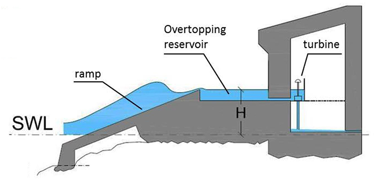
Figure 1. OBREC illustration (Source: Iuppa et al., 2016).
Critical design parameters are the crest freeboard Rc (m), that describes the height between the upper point of the sloping plate of the front reservoir and MSL, and the reservoir width Br (m), both illustrated in Figure 2. These two parameters should be selected in conjunction, allowing maximum wave overtopping inflow, and forming along with the length of the device, the suitable capacity of the reservoir, based on the prevailing wave conditions of each area. Furthermore, the length of the sloping plate, ultimately affects the behavior of the incoming water, as it determines Rc. Finally, careful design is required to avoid overtopping at the rear side of the structure.
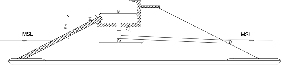
Figure 2. Depiction of OBREC parameters.
The aim of OBREC devices is to maximize the amount of wave overtopping inflow in the reservoir, creating a sufficient water column height, in order to produce energy. The efficiency of the device is proportional to the amount of water that enters the tank as well as to the hydraulic height of the water above the water turbine, Hk. The latter comprises the water column in the reservoir, denoted as h1 and the water column inside the pipe above the water turbine, denoted as hs. The elevation of the water turbine must be at least at the level of MSL or above, ensuring water flow.
Kaplan turbine is the most efficient option for such small head systems as OBREC, as it can maintain a high efficiency of the device in the varying wave field. To maximize the generated energy amount, careful design of the reservoir must precede for the proper and combined selection of the dimensions of crest level Rc and the width of the reservoir Br, per m length of the device, allowing maximum inflow and ensuring the necessary hydraulic load.
The wave overtopping equation that is used in this study, q, applies in the case of smooth steep low crested structures, according to EurOtop Manual (2007):
where: q defines the mean wave overtopping inflow (m3/s/m), Hm0 defines the incident wave height (m) and Rc defines the crest level (m).
The range of implementation of this equation is described by the following inequalities:
The above inequalities refer respectively to the slope of a breakwater, measured in rad, and to the dimensionless relative wave height, which is defined by the ratio Rc/Hm0. According to the EurOtop Manual, the reliability of the above equation is expressed considering that the factor (−2.6), which appears in Equation (1), is a stochastic variable that follows a normal distribution with mean (−2.6) and standard deviation σ = 0.35.
The power of the water turbine is given by the following equation:
where ρ = 1,000, is the water density (kg/m3), g = 9,81, is the gravitational acceleration (m2/s) qk, s, describes the inflow and in this problem is identified with wave overtopping inflow, q (m3/s/m), Hk, defines the hydraulic height of water above water turbine (m) and nhydro, defines the hydraulic efficiency of the water turbine.
The hydraulic efficiency of the OBREC device, nhydro, is defined as the proportion of the hydraulic power and the wave power and indicates how much percentage of wave power can be harvested every times the wave is acting on that structure. It is described by the ratio (Kofoed, 2000; Lander, 2012): . Phydro defines the power of collected waves and Pwave defines the initial wave power that runs in the breakwater, calculated by the following respective equations:
The hydraulic efficiency of devices such as OBREC usually ranges between 10 and 30% (Kofoed, 2000; Lander, 2012; Musa et al., 2016).
Objective—Problem Configuration
Introduction
The proposed methodology aims to identify the optimal combination of crest height and width of OBREC reservoir, in order to maximize its performance, through an optimization methodology. Initially, wave data from the case-study area of application, the city of Heraklion in the Greek island of Crete, will be presented. Then the structural features of the OBREC device and the breakwater are being defined (energy breakwater OBREC). Afterwards, the configuration of the optimization model is developed, through the identification of the objective function, the decision variables and the constraints of the problem.
The optimization problem is solved using a specially designed optimization software based on Harmony Search Algorithm (HSA). This software was selected after being extensively tested on benchmark optimization problems and was considered adequate and efficient enough to meet the non-linearities of the OBREC design problem. Finally, further analysis and evaluation of the exported results from the program will be performed, aiming to find the overall optimal solution.
Case-Study Area: The Port of Heraklion, Crete
Crete's energy supply system is isolated from the mainland and presents significant energy supply problems due to the limited coverage of the island's electricity needs especially during the summer months and the so far limited introduction of Renewable Energy Sources (RES). At the same time, the ongoing impacts of climate change, calls for the need to redesign the harbor structures, as well as the effort to cover the area's energy needs in accordance with the principles of sustainable development. Heraklion, because of its wave and wind field, is the ideal location to examine the performance of OBREC device in a breakwater (see Table 1).
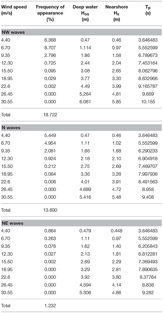
Table 1. Significant wave height, peak period, and frequency of appearance offshore the Heraklion port and in front of the breakwaters.
It becomes apparent that apart from its contribution to the energy requirements of the area, OBREC will contribute also to the protection of the port, whose needs are growing due to climate change. The prevailing winds that affect the behavior of the energy breakwater are N, NW, NE directed. OBREC performance is examined for all representative significant wave heights created by the aforementioned wave directions and for a wind strength range of 3–11 Beaufort (Bf). This leads to a total number of 27 wave conditions for which the optimal dimensions of OBREC are sought.
Design Characteristics of OBREC System
The breakwater, in which the OBREC device will be placed, follows the principles of a conventional breakwater with inclined slopes. The optimization can be achieved through the construction of a smooth, impermeable, low steep crested structure, which is described by water overtopping inflow Equation (1). The breakwater slope is defined as 1:2, a value that is expected to contribute to the optimal functioning of the structure. The dimensioning of the breakwater is based on the worst expected significant wave height that prevails in the study area, Hs = 6.081 m and accounting for shoaling and refraction phenomena, the design is ultimately carried out for a wave height of Hs = 5.294 m. The crest height is set at 5.80 m while its width at 5 m. The construction of a smooth impermeable layer of reinforced concrete on the open sea side is proposed for assisting wave climbing. The armor layer of the energy breakwater is made of artificial rocks and its construction depth is set at 10 m.
A pre-selected water turbine of Kaplan type is considered and it is placed at a level of +0.05 m above MSL. The size and efficiency of the turbine of the energy breakwater remains stable and does not interfere into the results produced by the present study. The height of the water turbine column is set at 0.40 m, while the water column above the water turbine is set at 0.40 m, ultimately forming the elevation of the bottom of the reservoir at a level height of +0.85 m, counting from MSL. The water flows out through a tube with a small inclination in the level of MSL. Finally, the construction of a “nose” is proposed at the back of the device, in order to increase water input in the reservoir and to reduce the number of waves that overtop in the rear side of the structure, up to 50–60%. Figure 3 forms a graphical demonstration of the described energy breakwater OBREC.
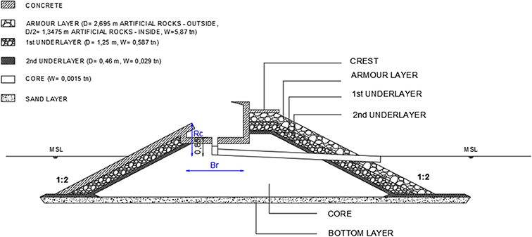
Figure 3. Graphical demonstration of a typical energy breakwater OBREC.
In the following paragraphs the nearshore wave transformation simulation model and the harmony search optimization algorithm used in this application are briefly presented.
Nearshore Wave Transformation Model
Linear wave propagation is simulated by applying a mild-slope model (Copeland, 1985; Watanabe and Maruyama, 1986), derived without the assumption of progressive waves. The model is based on the hyperbolic-type mild slope equation and is valid for a compound wave field near coastal structures where the waves are subjected to the combined effects of shoaling, refraction, diffraction, reflection (total and partial) and breaking. The module consists of the following pair of equations (Copeland, 1985; Watanabe and Maruyama, 1986):
where η is the surface elevation, Uw the mean velocity vector Uw = (Uw, Vw), d the depth, Qw = Uw hw = (Qw, Pw), hw the total depth (hw = d+η), c the celerity, and cg the group velocity. The term νh is an horizontal eddy viscosity coefficient introduced in order to include breaking effects based on the formulation of Battjes (1975):
where D is the dissipation of wave energy expressed as:
where Hm is the maximum wave height, ρ the water density, f the wave frequency, and Qb the probability for a wave to break at a depth, expressed as (1–Qb_/(lnQb) = (Hrms/Hm)2 according to Battjes and Janssen (1978). The mean square wave height Hrms is calculated from Hrms = 2 (<2η2>)1/2, with the brackets denoting a time-mean quantity.
The present model is a linear one, and it is not capable of describing waves in the swash zone, i.e., wave propagation on dry bed (‘negative' depth). The water depth from the rundown point (i.e., depth equal to R/4; R is the runup height) and up to the runup point (i.e., depth equal to -R) is considered to be constant and equal to R/4.
The model is adapted for applications based on the following:
• The input wave is introduced at a line inside the computational domain according to Larsen and Dancy (1983) and Lee and Suh (1998).
• A sponge layer boundary condition is used to absorb the outgoing waves at the four sides of the domain (Larsen and Dancy, 1983).
• The presence of vertical structures is incorporated by introducing a total reflection boundary condition (Uw = 0 or Vw = 0).
• Partial reflection is also simulated, by introducing an artificial eddy viscosity coefficient νh. The values of νh are estimated from the method developed by Karambas and Bowers (1996), using the reflection coefficient values given in the literature.
The numerical solution is based on the well-documented explicit second order finite difference staggered scheme using a mid-time method (Watanabe and Maruyama, 1986).
Using the wind data for the specific area from the Greek Metereological Service and applying the JONSWAP wave prediction method, the significant wave heights, the peak periods, and the frequencies of appearance of offshore waves were deduced (Liapis and Pantelidou, 2014). Table 1 shows the results of the JONSWAP method (deep water wave significant height Hos, offshore the Heraklion port) and the numerical model (Hs in front of the breakwater).
The computational domain covers a nearshore area of 4,000 ×1,800 m. The grid spacing is dx = 2.0 m and the time step 0.025 s. The offshore wave input is taken from Table 1.
Harmony Search Algorithm
The Harmony Search Algorithm (HSA) is a metaheuristic optimization method inspired by music harmony. It was first introduced by Geem (2000) in his Ph.D. thesis. This algorithm is based on a stochastic random search technique whose natural corresponding system is the process for the search of a better harmony by musicians. The Harmony Search Algorithm was inspired by the way a musician plays within a music group. During rehearsals or a concert, a musician has three choices:
i. To play the known—basic melody of the musical piece. This melody is known as the “theme” and it characterizes every piece. It is obviously known and already in the memory of the musician.
ii. To play something similar to the basic melody. To slightly change the “theme” enriching the piece with notes never played before.
iii. To start an improvisation by selecting new note sequences that will form a completely new music material.
The Harmony Search Algorithm is a stochastic meta-heuristic method based on the sequential production of possible solutions. It belongs to the category of “neighborhood meta-heuristics” that produce one possible solution per iteration. This procedure is completely different from that of the population methods that produce a number of possible solutions in every iteration (e.g., genetic algorithms).
Every possible solution consists of a set of values of the decision variables of the function that needs to be optimized. Each one of these sets of values is called a “Harmony.” During the optimization process, a number of “harmonies” equal to the “Harmony Memory size” are stored in the “Harmony Memory” (HM), a database that includes the produced set of solutions. The algorithm ends when the predefined total number of iterations has been achieved.
The simplicity, the fast convergence and the ease of programming of the algorithm have contributed in the spreading of the applications of HSA in various fields. HSA applies the three following procedures in every iteration. Procedure “b” is used (in a percentage) only if procedure “a” is activated. Option “c” is applied every time procedure “a” is not selected:
a) HSA is choosing any value from HS Memory. This process is defined as Memory Consideration and it is very important because it ensures that good harmonies (values that give good results) will be considered through the solution. Moreover, these “good” harmonies will be the material (similar with parents in Genetic Algorithms) for the creation of new, even better harmonies. In order to use this process effectively, Harmony Memory Considering Rate (HMCR) was defined. This index will specify the probability that a new harmony will include a value from the historic values that are stored in the Harmony Memory. If this rate is too low, only few elite harmonies will be selected. As a result HSA will converge slowly. Of course an HMCR value of 1.0 is not recommended because the exploration of the entire feasible range will be obstructed and optimization will fail. Typical values of HMCR are always >70%.
b) Every component of the new harmony chosen from HM, is likely to be pitch-adjusted. For example a Pitch Adjusting Rate (PAR) of 10%, indicates that algorithm will choose neighboring values for the 10% of the harmonies chosen from HM. The new harmony will include the value x which will be:
where, xi is the existing pitch stored in HM, Random is a random number between 0 and 1, and bw is the bandwidth of the adjustment.
c) The third choice is to select a totally random value from the possible value range. Randomization occurs with probability (100-HMCR)% and increases the diversity of the solutions. Although pitch adjustment has a similar role, it is limited in a local area. Randomization can drive the algorithm to explore the whole range and attain the global optimality.
The contribution of the authors of this paper to the development of the Harmony Search Algorithm as a widely recognized, highly credible optimization method for the solution of hydraulic engineering related problems is significant as expressed through a number of publications (Kougias and Theodossiou, 2011, 2013; Kougias et al., 2012, 2014, 2016; Theodossiou and Kougias, 2012; Theodossiou et al., 2016; Antoniou et al., 2017).
Optimization Model
The aim of the present study is to maximize the energy that is produced from OBREC. Because of this, the objective function of the problem is defined as:
which takes its final form after further elaboration of Equation 3:
The decision variables are included in both the objective function (Equation 11), and the constraints (Equation 13), in order to be determined by the optimization software. The decision variables of the problem are defined as the crest height Rc (m), X1 = Rc and the width of reservoir Br (m), X2 = Br. In addition, a third decision variable is used which represents the height of the water in the tank, X3 = h1. Its presence is necessary as it appears on the objective function and indicates the water height in the reservoir in every scenario. Also, through X3, the width of the reservoir is being calculated manually, after the programme results. HSA programme calculates the values of the decision variables X1, X3. The problem is formed based on the cross-sectional surface area of the reservoir of OBREC per current meter length, as shown in the graphic representation of Figure 3. According to that, the width Br (m), will be calculated through the cross-sectional area of the reservoir per current meter length and hence will result from the well-known equation of trapezoid area, which after conversions ends up in the following equation:
The constraints defining the problem are:
The HSA software has been executed for all the prevailing wave conditions in the area of study, emerging a total of 27 different size scenarios of the OBREC device. Each scenario presents the geometric shape of the reservoir that maximizes the power of the turbine, for the steady wave condition that has been introduced as input to the programme. Therefore, the results are not final and must be further processed by analyzing the behavior of the reservoir of each scenario in all wave conditions annually, so as to assess the real behavior and performance of OBREC.
An indicative calculation of the programme is presented in Table 2 for the OBREC device scenario 4 (considering the corresponding representative significant wave height for a NW prevailing wind of 6 Bf scale).
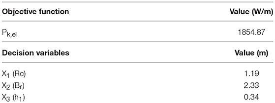
Table 2. Optimal solution for OBREC device scenario 4.
From the output results it was concluded that in any scenario, the dimensions of the reservoir are determined in order to allow maximum water storage. Therefore, in the problem it is considered that the cross-sectional area of the reservoir equals the wave overtopping inflow per meter and per second.
Analysis of the Scenarios
The behavior of OBREC reservoir must be tested for all the representative wave conditions that describe a full annual cycle in the area of study. Because water overtopping inflow coincides with the cross-sectional area A of the reservoir that stores the overtopping water per meter and per second, q = A holds in any case. So, this can be compared every time with the required water amount in order to fill the area of the reservoir for each scenario, defined as Afull. In each representative wave of the prevailing wind conditions, if the area filled by the incoming water is greater than Afull, it means that the cross-section of the reservoir overflows and subsequently Afull is used in the objective function in the place of q. Otherwise, the q value is used. Figure 4 presents the results of this application for wave scenario 4 that represents a NW wind condition of 6 Bf.
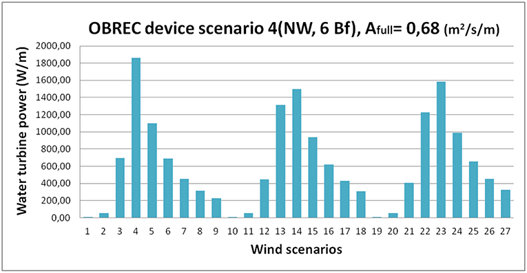
Figure 4. Analysis results of the indicative OBREC device scenario 4.
The process described above investigates the behavior of each OBREC device scenario in all waves induced by the prevailing wind conditions. However, in order to calculate the annual performance of OBREC in every scenario, wind occurrence frequency should also be taken into account, so that in the end, the cumulative performance per meter of length of the structure could be calculated. Also, an application of the annual performance of a total of 100 m length energy breakwater will be presented, for which the results of the energy performance over an annual cycle for each scenario of the OBREC reservoir will be assessed in order to select the optimal solution. The annual energy performance is calculated by the equation:
where:
• ngen, defines the performance of the electric generator. The value selected here is ngen = 0.45, as a realistic and expected value of performance.
• Pk, el, defines the power of the water turbine.
• f, defines wind frequency (%).
Figures 5A,B, present the annual energy performance for all the different scenarios of the OBREC device, as well as the corresponding annual energy performance for the indicative energy breakwater length of 100 m.
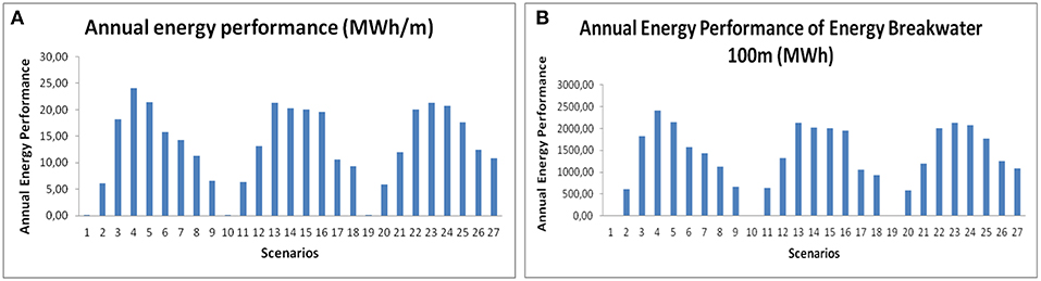
Figure 5. (A) Annual energy performance for every OBREC device scenario per current length. (B) Annual energy performance for every OBREC device scenario for an energy breakwater of 100 m length.
It should be noted that apart from each scenario's performance, the extra energy that can be produced because of the swell wave phenomenon can also be taken into account. Swell wave is defined as a wave that is not generated due to weather phenomena observed over time, but due to former wind conditions in the region, sometimes even days before, or even in another area. No adequate data exist yet to estimate the extra energy that can be generated by this phenomenon, however experimental tests have emerged that OBREC might render about 20% more energy in each scenario, due to swell waves. Figure 6 presents the overall final results of the annual energy production for all the OBREC device scenarios for an energy breakwater length of 100 m.
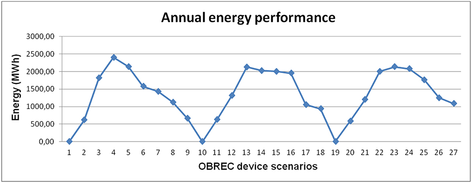
Figure 6. Annual energy performance for all OBREC device scenarios.
Assessment of Scenarios and Optimal Solution
The first criterion will assess the resulted OBREC device scenarios for an energy breakwater length of 100 m based on their maximum annual energy efficiency. According to Figure 6 and based on this criterion only, the optimal scenario is 4, with an annual performance of 2404.60 MWh. A group of solutions will also be considered acceptable at this point, whose results have little deviation from the maximum performance of the device scenario 4. This group is formed by the scenarios that show annual performance >2,000 MWh. The selected scenarios based on this first criterion are shown in Table 3.
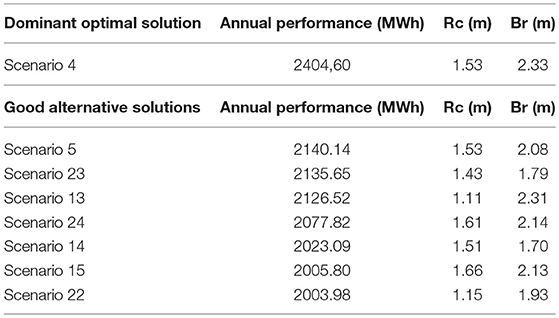
Table 3. OBREC device solutions based on maximum annual energy performance criterion.
In order to select the optimal solution, further processing will be conducted, based on two simple but significant criteria that can effectively assess all scenarios. This methodology could lead to different scenarios, ones that did not appear to be good choices or were not initially selected based on the first criterion, to be assessed as optimal solutions.
Initially, criterion Eff is being defined as . This ratio determines a simplified concept of efficiency of the device. However, it is a significant parameter that shows the importance of the energy generated by the device, based on its capacity. Thus, high values of Eff show that each reservoir scenario produces a significant amount of energy, given its capacity.
In the present study emphasis is given on the generated energy, without using data related to transport, storage and distribution of this energy amount. So, a full economic evaluation has not been conducted at this stage and could be the suggested as future research on the topic. However, it becomes apparent that the optimal solution is not necessarily the one that provides the maximum energy amount, if it could be possible to design a smaller, but more efficient reservoir, thus reducing the overall cost. Since some costs are constant, any financial difference will emerge from the circumferential length of the reservoir cross-section in each scenario. Given the selected length of 100 m of the structure, the feature that changes the capacity of the reservoir is the circumference of its cross-section. The colored part, defined as LOBREC, is what varies in each scenario's reservoir (Figure 7) and changes the cost of its construction.
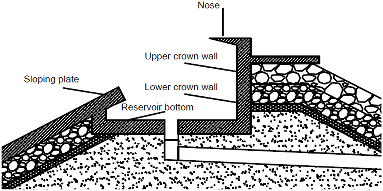
Figure 7. Definition of LOBREC (based on: Contestabile et al., 2015).
The combination of LOBREC parameter with the Eff index will further assess the accepted scenarios based on the first criterion while it is possible to highlight some others. What will determine the optimal scenarios will be the comparatively high values of ratio Eff, combined with comparatively smaller length values of LOBREC.
By applying these criteria in all considered different OBREC device scenarios, the results showed that the alternative solutions that combined higher prices of the Eff criterion, with smaller values of index LOBREC and with high annual energy performance values, are amongst the same scenarios that were selected during the first stage of the assessment.
However, scenarios 4, 13, 22, 23, as shown in Table 4, are those whose behavior is deemed most optimal according to all three criteria, forming the final acceptable group of optimal scenarios. The performance of all the final selected scenarios is expected to be high.
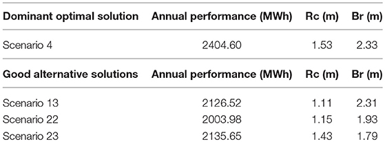
Table 4. Final optimal solutions.
Conclusions and Proposals
The proposed methodology highlights a group of good alternative, “efficient” and acceptable OBREC device scenarios combined with the derived optimal solution, whose energy performance is considered satisfactory. According to Eurostat data, the proposed optimal scenario 4, can meet the needs of approximately 687 households. Also, due to swell wave phenomenon, the estimated performance of OBREC may raise even by 20%. Finally, it was observed that in cases of N and NW winds, that are the most frequent in Heraklion, OBREC performance maximized in all scenarios, ensuring the proper exploitation of wave energy of the area.
For further optimization of OBREC systems, a careful selection of electrical equipment is proposed. Also, the selection of the appropriate pipe diameter is necessary, based on the dimensions of the reservoir. Alternatively, the device can include more than one tubes in the reservoir. The number of the tubes that will operate should depend on the incoming amount of overtopping water. Finally, the increased requirements of installation and maintenance of the device are a dominant prerequisite in order to ensure high performance of the system.
The proposed wave energy converter, OBREC, is an option with high estimated energy performance, while considered as an economically sustainable solution, where its cost is covered by the benefits of its operation both as a work of protection, and as an energy producing device. The proposed methodology aims to highlight the great contribution of optimization to the improvement of the performance of OBREC device. The integration of optimization techniques in the design of OBREC system is absolutely necessary in order to ensure in all cases proper operation and high energy performance.
Author Contributions
V-EK was responsible for executing the calculations. NT was responsible for the implementation of the optimization model. TK was responsible for the implementation of the wave propagation model.
Conflict of Interest Statement
The authors declare that the research was conducted in the absence of any commercial or financial relationships that could be construed as a potential conflict of interest.
References
Antoniou, M., Theodossiou, N., and Karakatsanis, D. (2017). Coupling groundwater simulation and optimization models, using MODFLOW and Harmony Search Algorithm. J. Desalin. Water Treat. 86, 297–304. doi: 10.5004/dwt.2017.20993
Battjes, J. A. (1975). “Modelling of turbulence in the surf zone,” in ASCE Symposium on Modelling Techniques (San Francisco, CA), 1050–1061.
Battjes, J. A., and Janssen, J. P. F. M. (1978). Energy loss and set-up due to breaking of random waves. Coast. Eng. 1978, 569–587. doi: 10.1061/9780872621909.034
Buccino, M., Stagonas, D., and Vicinanza, D. (2015). Development of a composite sea wall wave energy converter system. Renew. Energy 81, 509–522. doi: 10.1016/j.renene.2015.03.010
Contestabile, P., Ferrante, V., Di Lauro, E., and Vicinanza, D. (2016). “Prototype overtopping breakwater for wave energy conversion at port of Naples,” Proceeding of the Twenty-Sixth International Ocean and Polar Engineering Conference (Rhodes), 616–621.
Contestabile, P., Vicinanza, D., Luppa, C., Cavallaro, L., and Foti, E. (2015). Innovative rubble mound breakwaters for wave energy conversion. J. Energ. Ambiente Innov. 47, 86–95.
Copeland, G. J. M. (1985). A practical alternative to the “mild-slope” wave equation. Coast. Eng. 9, 125–149. doi: 10.1016/0378-3839(85)90002-X
Falcao, A. F. D. O. (2010). Wave energy utilization: a review of the technologies. Renew. Sustain. Energy Rev. 14, 889–918. doi: 10.1016/j.rser.2009.11.003
Folley, M., Whittaker, T., and Osterried, M. (2004). “The oscillating wave surge converter,” in 14th International Offshore and Polar Engineering Conference (Toulon).
Geem, Z. (2000). Optimal design of water distribution networks using harmony search (Ph.D., thesis). Korea University, Seoul, South Korea.
Gravas, A., Savvidis, Y., and Koutitas, C. (2012). Modelling study of wave energy harnessing port structures. Fresenius Environ. Bull. 21, 3069–3076.
Iuppa, C., Contestabile, P., Cavallaro, L., Foti, E., and Vicinanza, D. (2016). Hydraulic performance of an innovative breakwater for overtopping wave energy conversion. Sustainability 8:1226. doi: 10.3390/su8121226
Karambas, T. V., and Bowers, E. C. (1996). Representation of partial wave reflection and transmission for rubble mound coastal structures. WIT Trans. Ecol. Environ. 12, 415–423.
Kofoed, J. P. (2000). Wave overtopping of marine structures—utilization of wave energy (Ph.D. thesis). Aalborg University. Hydraulics & Coastal Engineering Laboratory, Department of Civil Engineering, Aalborg University, Aalborg, Denmark.
Kofoed, J. P., Frigaard, P., Friis-Madsen, E., and Sørensen, H. C. (2006). Prototype testing of the wave energy converter wave dragon. Renew. Energy 31, 181–189. doi: 10.1016/j.renene.2005.09.005
Kougias, I., Karakatsanis, D., Malatras, A., Monforti-Ferrario, F., and Theodossiou, N. (2016). Renewable energy production management with a new harmony search optimization toolkit. Clean Technol. Environ. Policy 18, 2603–2612. doi: 10.1007/s10098-016-1173-4
Kougias, I., Katsifarakis, L., and Theodossiou, N. (2012). Medley multiobjective harmony search algorithm. Application on a water resources management problem. Euro. Water 39, 41–52.
Kougias, I, Patsialis, T., Theodossiou, N., and Ganoulis, J. (2014). “Chapter 4: Hydropower projects within a municipal water supply system. Optimum allocation and management using harmony search,” in Exploring Innovative and Successful Applications of Soft Computing, eds A. Masegosa, P. Villacorta, C. Corona, M. Cascales, M. Lamata, and J. Verdegay (IGI Global), 59–75. doi: 10.4018/978-1-4666-4785-5.ch004
Kougias, I., and Theodossiou, N. (2011). Application of the Harmony Search optimization algorithm for the solution of the multiple dam system scheduling. Optimiz. Eng. 14, 331–344. doi: 10.1007/s11081-011-9183-x
Kougias, I., and Theodossiou, N. (2013). Multiobjective pump scheduling optimization using Harmony Search Algorithm (HSA) and polyphonic HSA. Water Resour. Manage. 27, 1249–1261. doi: 10.1007/s11269-012-0236-5
Lander, V. (2012). Optimization of the hydrodynamic performance of overtopping wave energy converters: experimental study of optimal geometry and probability distribution of overtopping volumes (Ph.D. thesis). Department of Civil Engineering, Ghent University, Ghent, Belgium.
Larsen, J., and Dancy, H. (1983). Open boundaries in short wave simulations—a new approach. Coast. Eng. 7, 285–297. doi: 10.1016/0378-3839(83)90022-4
Lee, C., and Suh, K. D. (1998). Internal generation of waves for time-dependent mild-slope equations. Coast. Eng. 34, 35–57. doi: 10.1016/S0378-3839(98)00012-X
Liapis, C., and Pantelidou, E. (2014). Design of a Wave Energy Converter breakwater at Heraklion harbour (Diploma thesis). Department of Civil Engineering, Aristotle University of Thessaloniki, Thessaloniki, Greece.
Musa, A., Maliki, Y., Ahmad, M., Yaakob, O., Samo, K., and Ibrahim, M. Z. (2016). Prediction of energy performance by adopting overtopping breakwater for energy conversion (OBREC) concept in Malaysia waters. J. Environ. Sci. Technol. 9, 417–426. doi: 10.3923/jest.2016.417.426
Theodossiou, N., Karakatsanis, D., and Fotopoulou, E. (2016). “Introducing novel optimization techniques in irrigation pipe network applications,” in 2nd EWaS International Conference (Chania).
Theodossiou, N., and Kougias, I. (2012). “Chapter 7: Harmony search algorithm,” in Heuristc Optimization in Hydrology, Hydraulics and Water Resources, ed K. L. Katsifarakis (W.I.T. Press), 117–140.
Vicinanza, D., Contestabile, P., Nørgaard, J. Q. H., and Andersen, T. L. (2014). Innovative rubble mound breakwaters for overtopping wave energy conversion. Coast. Eng. 88, 154–170. doi: 10.1016/j.coastaleng.2014.02.004
Vicinanza, D., Di Lauro, E., Contestabile, P., Gisonni, C., Lara, J. L., and Losada, I. J. (2019). Review of innovative harbor breakwaters for wave-energy conversion. J Waterway Port Coast. Ocean Eng. 145, 1–18. doi: 10.1061/(ASCE)WW.1943-5460.0000519
Vicinanza, D., Margeritini, L., Kofoed, J. P., and Buccino, M. (2012). The SSG wave energy converter: performance, status and recent developments. Energies 5, 193–226. doi: 10.3390/en5020193
Watanabe, A., and Maruyama, K. (1986). Numerical modelling of nearshore wave field under combined refraction, diffraction and breaking. Coast. Eng. Jpn. 29, 19–39. doi: 10.1080/05785634.1986.11924425
Keywords: optimization, OBREC, waves, renewable energy, breakwaters
Citation: Kralli V-E, Theodossiou N and Karambas T (2019) Optimal Design of Overtopping Breakwater for Energy Conversion (OBREC) Systems Using the Harmony Search Algorithm. Front. Energy Res. 7:80. doi: 10.3389/fenrg.2019.00080
Received: 03 January 2019; Accepted: 31 July 2019;
Published: 14 August 2019.
Edited by:
Riccardo Maria Pulselli, University of Siena, ItalyReviewed by:
Marco Aiello, University of Stuttgart, GermanyDiego Vicinanza, University of Campania Luigi Vanvitelli, Italy
Pasquale Contestabile, Università degli Studi della Campania L. Vanvitelli, Italy
Copyright © 2019 Kralli, Theodossiou and Karambas. This is an open-access article distributed under the terms of the Creative Commons Attribution License (CC BY). The use, distribution or reproduction in other forums is permitted, provided the original author(s) and the copyright owner(s) are credited and that the original publication in this journal is cited, in accordance with accepted academic practice. No use, distribution or reproduction is permitted which does not comply with these terms.
*Correspondence: Nicolaos Theodossiou, bmlrdGhlb2RAY2l2aWwuYXV0aC5ncg==