 Xiaolin Zhang
 Shuai Deng
 Li Zhao
 Wen Su1,2
- 1Key Laboratory of Efficient Utilization of Low and Medium Grade Energy, Tianjin University, Tianjin, China
- 2School of Energy Science and Engineering, Central South University, Changsha, China
In order to make better use of the thermal energy at low and medium temperature and improve the organic Rankine cycle performance, the power, and ejector-refrigeration system has been put forward and a lot of research has been carried out. This article presents a new study of the combined system and the key component ejector using the zeotropic mixture R134a/R123 as working fluid. First, the influence of heat source temperature, turbine outlet pressure, and different mixture compositions on the performance of the combined system and ejector were analyzed. It can be found that entrainment ratio is not sensitive to the change of heat source temperature. Through exergy analysis of the combined system, it can be found that ejector, evaporator, and condenser take up for most exergy destruction of the system. The result illustrate that exergy destruction mainly occurs in the component of ejector, which can reach 50.28%. Then, the relationship between input heat of ejector, net power change value and power saved by ejector was compared. It can be found that net power reduction is less than power saved by ejector and refrigeration output. Finally, the exergy efficiency of ejector was defined and the effects of other parameters on it are analyzed. The results show that the exergy efficiency of ejector and COP are oppositely changing.
Introduction
Constant increase in power and refrigeration demand calls for new technology that is more economical, safe, and environmental protection. The ORC (organic Rankine cycle) takes on the advantages of low temperature requirement, high efficiency and simple structure. This important characteristic makes it have great application potential in the industrial and waste-heat recovery (Wang et al., 2014). The ejector, which could realize the function of pressurization, vacuum and mixed, is a simple, low cost, easy-to-maintain component in thermodynamic system (Tashtoush et al., 2015). Therefore, ejector has great potential in energy utilization and environmental protection. The combined system can fully utilize the technical advantages of ORC and ejector-refrigeration cycle to simultaneously meet the user's power and cold demand. At the same time, the combined system can share some equipment and use the same working fluid, greatly saving in initial investment. The combined system is a solution to effectively recover low and medium grade energy to produce electricity and cold (Yang et al., 2016).
Existing literature have studied the power and ejector-refrigeration system from the aspects of working fluid, ORC system, ejector-refrigeration system, and so on. In order to improve system performance, zeotropic mixtures were used. Feng et al. (2017) researched the operational characteristic of:
ORC system using R245fa, R123, and their mixtures. According to the experimental result, it was found that the mixture working fluids increase pump power consumption. Meanwhile, the improvement of working fluid pump performance can effectively improve the ORC system performance. The zeotropic mixture has better performance of thermodynamic and economic than the pure working fluid. Yang et al. (2015) showed that the mixture isobutane/pentane (50/50) has the highest exergy efficiency of 7.83%. Wang and Zhao (2009) found that the thermal efficiency and collector efficiency of zeotropic mixture are higher than R245fa. Net power of the system with zeotropic mixture M3 (R245fa/R152a, 0.7/0.3) is higher than that with M1 (R245fa) and M2 (R245fa/R152a, 0.9/0.1) by 29.10 and 28.03%, respectively. Xu et al. (2018) added working fluid thermodynamic coordinates based on the original research and proposed a three-dimensional construction method of thermodynamic cycles. By considering the working fluid characteristics in each process, the three-dimensional construction method makes the thermodynamic cycle closer to the ideal cycle. Therefore, the system performance can be improved by using mixed working fluids.
The combined system is a relatively simple form of power-cooling combined supply, so it is more acceptable and practical to be applied in small-sized filed of low and medium temperature heat source. Wang et al. (2009) developed a combined cycle of organic Rankine cycle and ejector-refrigeration cycle. The thermal efficiency and exergy efficiency can reach 27.51 and 14.92%, respectively. Habibzadeh et al. (2013) researched the combined system performance with five working fluids (R123, R141b, R245fa, R600a, R601a). It was found that under optimum conditions, R141b has the lowest optimum pressure and thermal conductance. However, R601a has the highest thermal efficiency and lower total exergy destruction in the optimum case. Wang et al. (2015) optimized solar CCHP (combined cooling, heating and power) cycle with the objective function of average useful output and total heat transfer area. In the combined system, ORC cycle and ejector-refrigeration cycle share the same heat source. The ejector-refrigeration cycle has good performance and the disadvantage is that the power output becomes less. Actually, further research needs to be carried out on the combined system modification, component optimization design to improve the energy utilizing efficiency of the system.
In refrigeration system, ejector can be used alone or in combination with other equipment as entrainment and compression equipment or expander. As a technique of more efficient low temperature heat recovery and use of energy, it has attracted new attention (Aidoun et al., 2019). Bai et al. (2016) used traditional thermodynamics and advanced exergy analysis methods to study ejector for improve freezer cycle of auto-cascade. The energetic analysis showed that the optimize system has better COP than the conventional freezer cycle, and COP and volumetric refrigeration property were increased by 0.20 and 0.28, respectively. Rahamathullah et al. (2013) not only focused on ejector background principles of design method, but also on ejector performance improvements in refrigeration system. Chen et al. (2013) revisited new technological developments in terms of ejector performance enhancement techniques and ejector-refrigeration system. Lin et al. (2012) developed the CFD simulation by using experimental data. The data was measured by multi-evaporator refrigeration system with ejector of Emers. The characteristic of variable cooling load and ejector pressure lift in refrigeration system with R134a were studied. It is efficient to use an adjustable ejector with a spindle to control the constant inlet pressure under low cooling loads conditions in order to maintain system stability. Hou et al. (2017) analyzed the performance of ejector used in refrigerator-freezer cooling system with a parallel hybrid ejector-based. The results show that the primary nozzle blocking percentage with a spindle has great influence on the property of ejector. Yang et al. (2015, 2016) theoretically studied the combined system with isobutane/pentane. The result reveals that the major exergy destruction occurs in the ejector. Thence, the ejector of the combined system need to conduct more research to detail the relationship between loss and profit.
In this paper, zeotropic mixture R134a/R123 was employed as working fluid to analyze the property of the combined system. The relationship between energy saving and exergy destruction was evaluated. Different from the traditional method which uses pressure lift ratio and entrainment ratio to evaluate the equipment property of ejector, the exergy efficiency of ejector was defined to evaluate its performance. At the same time, as a kind of low and medium temperature waste heat with abundant resources, the influence of flue gas temperature (413.15-463.15k) on system performance was analyzed. In addition, the effects of thermodynamic parameters also were investigated, such as turbine outlet pressure, heat source temperature and different working fluid compositions.
The Combined Power and Ejector-Refrigeration System
Thermodynamic Cycle
The combined system is presented by Figure 1. The combined system consists of a working fluid pump, an evaporator, a turbine, a condenser, a throttle valve, an ejector and a refrigerating evaporator. In the combined system, the working fluid R134a/R123 is heated to (state 2) superheated gas from the working fluid pump outlet (state 1). Then, superheated gas goes into the turbine (state 2) and generates electricity through expansion. The turbine outlet (state 3) as a primary fluid turns into the ejector. When the primary fluid (state 3) transits the convergent-diverging nozzle inside the ejector, it accelerates to a supersonic condition (state 3a). Low pressure flow (state 9) as secondary flow of ejector is sucked from the refrigerating evaporator. In the mixing chamber of ejector, the two streams are mingled together. In the diffusion chamber of ejector, the flow experiences a shock wave and a pressure lift (state mo-4). The gas is cooled to saturated liquid in condenser (state 4–5). Part of working fluid (state 5) flows the working fluid pump (state 6) while the rest (state 7) expands in the throttle valve. Then, the two-phase working fluid (state 8) flows the refrigerating evaporator. It is heated to saturated gas (state 9) in a refrigerating evaporator. The system goes through a complete cycle.
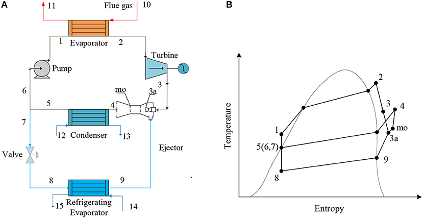
Figure 1. Schematic diagram of the combined power and ejector-refrigeration system: (A) system chart, (B) T-s schematic diagram.
In this paper, the combined system was simulated by using flue gas waste heat as heat source. As the complex mixing law of two working fluid mixtures, it is difficult to choose the compositions of the mixtures. The objective of this article is to analyze the combined system performance with working fluid of R134a/R123. Therefore, the characteristic of both ORC subsystem and ejector-refrigeration subsystem must be considered. The rational selection of working fluid not only should consider the thermodynamic properties, but also need to consider chemically stable, safe and environmental protection property. R134a is widely used in refrigeration system of low and medium temperature environmental. Meanwhile, R123 is a very effective and safe refrigerant. Due to its good comprehensive performance. They are typical zeotropic mixtures, with noteworthy temperature glides in the evaporator, refrigerating evaporator, and condenser. Thus, R134a/R123 is a specific mixed object in this research. At the same time, other simulation and experiments with R134a/R123 as working fluid, reference (Du and Xu, 2009; Zhang et al., 2014; Zhong et al., 2018). The main environmental protection parameters and thermal parameters of R134a and R123 are listed in Table 1.
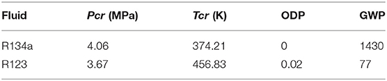
Table 1. The property of working fluid.
Mixture R134a/R123 was elected as working fluid of the combined system. The thermodynamic parameters were obtained by software of REFPROP 9.1. Some simplifying assumptions were made for the theoretical simulation, listed in Table 2. Figure 3 shows the exergy destruction distribution of equipment in combined system. This is the result under heat source temperature is 453.15K, evaporation temperature is 363.15K, mass fraction of R134a = 30% and turbine outlet pressure is 1.53MPa. It can be found that the proportion of exergy destruction in ejector is the largest at 50.28%, followed by evaporator 27.6% and condenser 17.54%. Similar results were found in Yang et al. (2016). Hence, ejector exergy destruction is very large in the simulation.
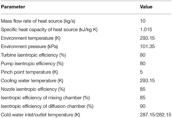
Table 2. Cycle parameter assumptions.
Thermodynamic Model
To simplify the theoretical calculation, some assumptions Table 2 and simplifications are made for the actual cycle thermal process, including:
(1) Condenser and refrigerating evaporator outlet are saturated liquid and saturated gas, respectively.
(2) The working fluid flow inside ejector is one-dimensional and stable.
(3) The throttling process is an isentropic process.
(4) Ejector inlet and outlet speeds are ignored.
Energy Analysis Model
The combined system model. The flue gas input energy in the evaporator is:
The mass flow rate of ORC subsystem can be expressed by:
The mass flow rate of ejector-refrigeration subsystem is calculated as:
The turbine output power is expressed as:
Refrigeration output of refrigerating evaporator is:
The power consumed by pump is defined by:
The net power output of ORC subsystem is:
The COP of the combined system is determined by:
The reduction or increase in net power of the ORC subsystem is calculated by:
0 is the reference point and k is other point.
The power saved by ejector is defined as:
Ejector input heat is defined by:
Ejector model. Ejector entrainment ratio is:
Ejector model consists of a nozzle, a mixing chamber and a diffusion chamber.
Motive nozzle efficiency:
By using the energy equation of motive nozzle, the speed of the nozzle outlet flow can be calculated as follows:
Compared with the primary fluid, the speed of secondary fluid can be neglected at nozzle outlet.
The momentum conservation equation:
Mixing efficiency:
Energy conservation equation of mixing section is:
Diffuser efficiency:
Mass fraction:
Exergy Analysis Model
Taking into account the fact that the kinetic and potential energies and chemical exergy are neglected in the exergy balance equations, exergy at each state point can be calculated by:
0 is the environmental status and i = 1-15.
The exergy destruction for the jth equipment:
The combined system exergy destruction can be formulated as follows:
Ejector exergy efficiency can be defined as follows:
The calculation process is shown in Figure 2. Matlab 2017 was used for calculation.
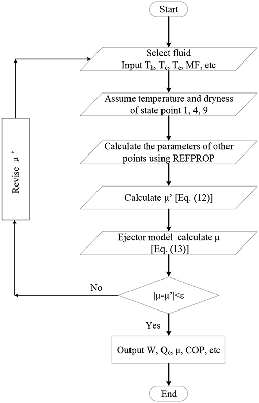
Figure 2. Simulation flowchart of the combined system performance analysis.
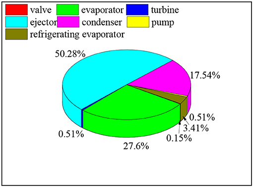
Figure 3. Exergy destruction distribution of equipment in the combined system.
Results and Discussion
In the combined system, scholars have done a lot of research on evaporator, condenser, turbine and pump. This article mainly focuses on factors that affect ejector performance. Compared with compressors, ejector consumes less power. Therefore, the relationship between saving power and exergy destruction in ejector requires more research. Many parameters affect net power and refrigeration output of the combined system. According to the research situation, this article studies the influence of turbine outlet pressure, heat source temperature and mass fraction on the performance of the combined system.
The Combined Power and Ejector-Refrigeration System
Figure 4A shows the impact of turbine outlet pressure and mass fraction on the combined system net power. This is the result under heat source temperature is 423.15K and evaporation temperature is 363.15K. The study found that net power W drops as turbine outlet pressure ranges from 1.13 to 1.53MPa. When turbine outlet pressure rises, turbine outlet temperature will increase, leading working fluid specific enthalpy to be higher. As a consequence, net power of the ORC subsystem also decreases according to Equation (7). At the same time, we can see that net power rises with the increase of R134a mass fraction. This indicates that under the same conditions, R123 has a lower working ability than R134a.
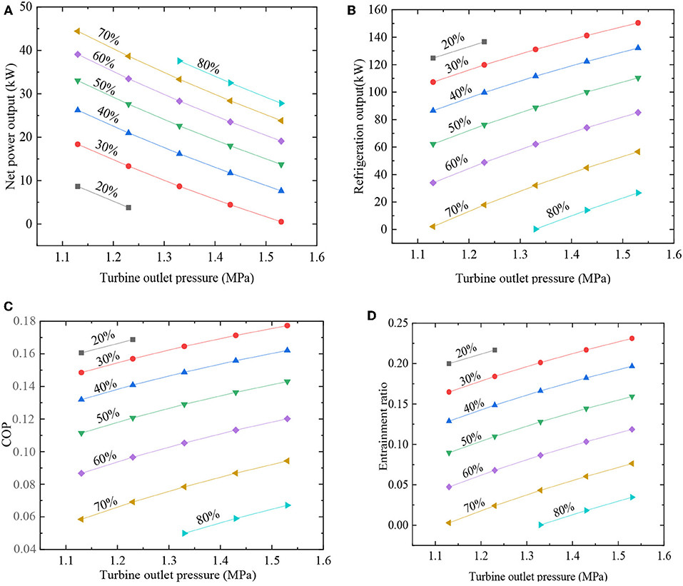
Figure 4. Effect of turbine outlet pressure and mass fraction. (A) Net power; (B) refrigeration output; (C) COP; (D) entrainment ratio.
Figure 4B reveals the impact of turbine outlet pressure and mass fraction on the ejector-refrigeration subsystem output. This is the result under heat source temperature is 423.15K and evaporation temperature is 363.15K. As is shown in Figure 4B, refrigeration output increases with turbine outlet pressure ranges from 1.13 to 1.53MPa. This is the result of ejector primary fluid pressure increases and second fluid pressure remains constant. Therefore, entrainment ratio keeps increasing in Figure 4D. That means an increase in refrigeration output. Meanwhile, net power decreases, but it's much less than refrigeration output increases. As a result, the COP also keeps increasing in Figure 4C. Figure 4C shows the impact of turbine outlet pressure and mass fraction on the COP. It is found that the COP keeps increasing with the turbine outlet pressure increase. Under the same condition, with the augment of mass fraction of R134a from 20 to 80%, net power increment is less than the reduction of refrigeration output, so COP decreases according to Equation (8).
Net power and refrigeration output with various of heat source temperature and mass fraction are shown in Figures 5A,B. This is the result under evaporation temperature is 363.15K and turbine outlet pressure is 1.53MPa. As seen, along with the augment of heat source temperature from 413.15 to 453.15K, net power and refrigeration output increases. This is due to the increase of R134a/ R123 mass flow rate in the ORC subsystem. This is the reason for the increase of refrigeration output. As the increase of R134a mass fraction, net power increases and refrigeration output decreases, which is similar to the results in Figures 4A,B. As we can see in Figure 5A, with mass fraction of R134a increases, net power increases more and more obviously. Net power and refrigeration output show opposite change trend with the increase of R134a mass fraction.
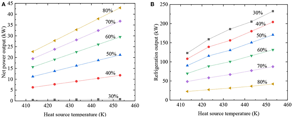
Figure 5. Effect of heat source temperature and mass fraction. (A) Net power; (B) refrigeration output.
Meanwhile, net power and refrigeration output increase as the increase of heat source temperature in Figures 6A,B. That's the result under mass fraction of R134a = 50% and turbine outlet pressure is 1.53MPa. Figure 6A also shows that the increase in evaporation temperature has a positive impact on net power. However, refrigeration output changes with evaporation temperature increases in the opposite trend in Figure 6B.
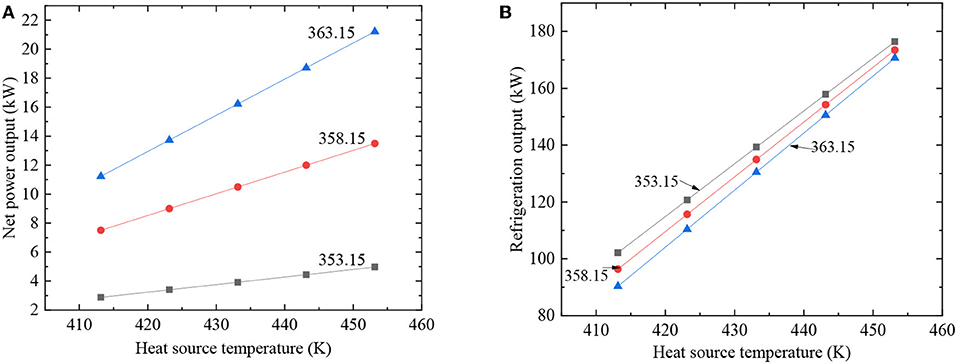
Figure 6. Effect of heat source temperature and evaporation temperature. (A) Net power; (B) refrigeration output.
Figure 7 shows the impact of evaporation temperature and mass fraction on net power, refrigeration output, COP and entrainment ratio. This is the result under heat source temperature of 423.15K and turbine outlet pressure is 1.53MPa. The results show that net power increases for as evaporation temperature increases from 348.15K to 363.15K in Figure 7A. However, refrigeration output shows an opposite trend in Figure 7B. It is found that COP keeps increasing as the evaporation temperature increases from 348.15K to 363.15K in Figure 7C. However, as mass fraction of R134a increases, COP and entrainment ratio decrease. At the same time, we can see that the influence of evaporation temperature on entrainment ratio almost can be ignored in Figure 7D.
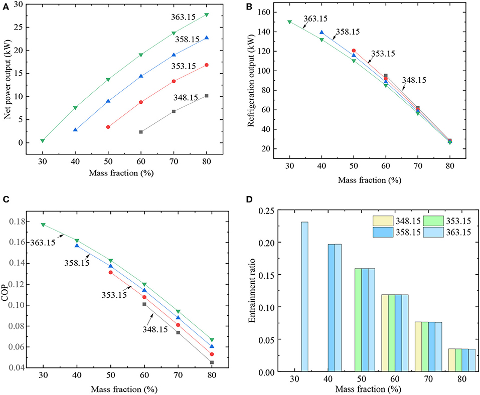
Figure 7. Effect of mass fraction and evaporation temperature. (A) Net power; (B) refrigeration output; (C) COP; (D) entrainment ratio.
Figures 8A–C, respectively illustrate exergy destruction in each equipment of the combined system with a function of turbine outlet pressure, heat source temperature and mass fraction. As we see in Figure 8, ejector, evaporator and condenser take up for most exergy destruction of the combined system. Exergy destruction rises with increase of turbine outlet pressure and heat source temperature in the combined system. This is mainly due to entrainment ratio increases, resulting in an increase in the exergy destruction of ejector. The R134a/R123 mass flow rate keeps increasing as heat source temperature increases and exergy destruction of the combined system also increases in Figure 8B. This is the result under evaporation temperature is 363.15K, mass fraction of R134a is 50% and turbine outlet pressure is 1.53MPa. The combined system exergy destruction reduces as mass fraction of R134a varies from 30 to 80% in Figure 8C. This is the result under heat source temperature is 423.15K, turbine outlet pressure is 1.53MPa and evaporation temperature is 363.15K. The exergy destruction of evaporator increases very few as R134a mass fraction varies from 30% to 80%. In contrast, exergy destruction greatly increases in ejector.
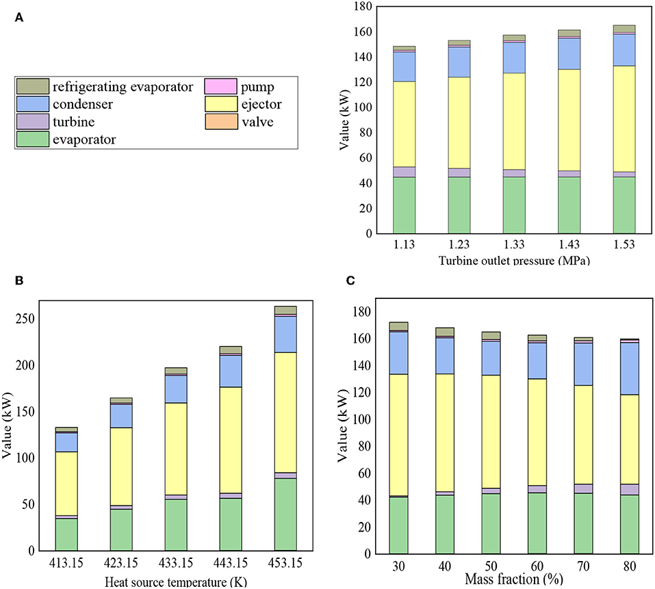
Figure 8. Distribution of components destruction of. (A) Turbine outlet pressure; (B) heat source temperature; (C) mass fraction.
The Key Component Ejector
Figure 9A reveals the impact of turbine outlet pressure on net power reduction, ejector heat input, refrigeration output and ejector saves power. This is the result under heat source temperature is 423.15K, evaporation temperature is 363.15K and R134a mass fraction = 50%. As pressure increases, ejector saves power increases and second fluid flow rate rises, which is caused by entrainment ratio increases in Figure 9A. As can be seen both ejector saves power and refrigeration output keep increasing as turbine outlet pressure from 1.13MPa to 1.53MPa. As ejector input heat increases, ejector saves power and refrigeration output augments, which is caused by entrainment ratio increases. At the same time, refrigeration output increases even more. Net power added value, ejector input heat, ejector saves power and refrigeration output distributions with heat source temperature are shown in Figure 9B. This is the result under evaporation temperature is 363.15K, R134a mass fraction = 50% and turbine outlet pressure is 1.53MPa. With the increases of R134a/R123 mass flow rate, the above parameter values also increase. Figure 9C illustrates the influence of mass fraction on net power added value, ejector input heat, refrigeration output, and ejector saves power. This is the result under heat source temperature is 423.15K, evaporation temperature is 363.15K and turbine outlet pressure is 1.53MPa. It is found that net power added value increases as R134a mass fraction increases from 30 to 80% to gets the maximum value = 27.29kW with mass fraction = 80%, but net power added value gets minimum value = 7.14kW with mass fraction = 40%. Because of the different working fluid compositions of zeotropic mixtures in liquid and vapor, the working fluid compositions in condenser, evaporator, and turbine are also different. It makes a difference in the ability to net power output. As display in Figure 9C, ejector input heat decreases as mass fraction increases. Because of the difference in the working fluid composition, input heat value is also different. Similarly, ejector saves less power. As ejector input heat decreases, refrigeration output and entrainment ratio are reduces.
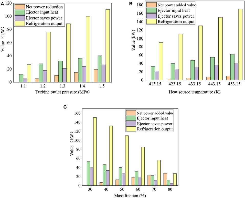
Figure 9. Effect on the performance of ejector and the combined system. (A) Turbine outlet pressure; (B) heat source temperature; (C) mass fraction.
Figure 10A illustrates the impact of turbine outlet pressure and mass fraction on ejector exergy efficiency. This is the result under heat source temperature is 423.15K and evaporation temperature is 363.15K. With the raises of turbine outlet pressure, ejector exergy efficiency increases. It can be found that the lower turbine outlet pressure, the lower ejector exergy efficiency. On the contrary, exergy efficiency of ejector is increased.
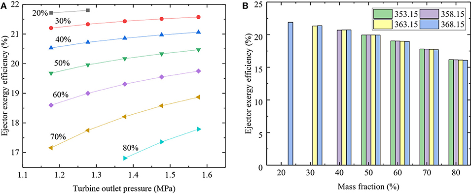
Figure 10. Effect on the ejector exergy efficiency. (A) Turbine outlet pressure and mass fraction; (B) mass fraction and evaporation temperature.
Figure 10B shows the relationship between ejector exergy efficiency and mass fraction and evaporation temperature. Ejector exergy efficiency = 21.89% for evaporation temperature is 368.15K, turbine outlet pressure 1.277MPa. This is the result of heat source temperature is 423.15K and mass fraction = 20%. And it achieves the maximum value when R134a mass fraction is 20%. With R134a mass fraction is 80%, ejector exergy efficiency yields a minimum value. Ejector exergy efficiency reduces when R134a mass fraction from 30 to 80%. This indicates that it is more suitable for the operation of ejector when mass fraction is higher of R123. Under the same operating conditions, evaporation temperature has little effect on exergy efficiency of ejector.
Conclusion
In this article, the ejector and power and ejector-refrigeration system with R134a/R123 were studied theoretically. The influence of turbine outlet pressure, heat source temperature, evaporation temperature and different working fluid compositions were analyzed. The following summaries can be obtained from this article:
(1) When mass fraction of R134a is 30%, the maximum COP and entrainment ratio are 0.18 and 0.23, respectively. This is the result under the heat source temperature is 423.15K, evaporation temperature is 363.15K and turbine outlet pressure is 1.53MPa.
(2) Net power reduction is 21.18kW far less than the power saved 28.85kW and refrigeration output 110.42kW by ejector brings. This is the result under the heat source temperature is 423.15K, evaporation temperature is 363.15K and R134a mass fraction = 50%.
(3) The ejector exergy efficiency was defined to analyze its performance. Entrainment ratio, refrigeration output and COP raises with the increase of the turbine outlet pressure. However, the exergy efficiency of ejector decreases. In the combined system, ejector exergy efficiency reaches a maximum of 59% when R134a/R123 (70/30).This is the result under the heat source temperature is 423.15K, evaporation temperature is 363.15K, R134a mass fraction = 70% and turbine outlet pressure is 1.13MPa.
Data Availability Statement
The datasets generated for this study are available on request to the corresponding author.
Author Contributions
SD and WS contributed conception and design of the study. WX performed the statistical analysis. XZ wrote the first draft of the manuscript. All authors contributed to manuscript revision, read and approved the submitted version.
The corresponding author takes primary responsibility for communication with the journal and editorial office during the submission process, throughout peer review, and during publication. The corresponding author is also responsible for ensuring that the submission adheres to all journal requirements.
Funding
This study was supported by China's national key research and development program (2018YFB0905103) and the National Natural Science Foundation of China (No. 51276123). TianJin talent development special support program high-level innovation and entrepreneurship team project and national Marine economy innovation and development demonstration project (BHSF2017-19).
Conflict of Interest
The authors declare that the research was conducted in the absence of any commercial or financial relationships that could be construed as a potential conflict of interest.
Acknowledgments
The National key research and development program of China (2018YFB0905103), National Natural Science Foundation of China (No. 51276123), TianJin talent development special support program high-level innovation and entrepreneurship team project and National Marine economy innovation and development demonstration project (BHSF2017-19) support this research.
References
Aidoun, Z., Ameur, K., Falsafioon, M., and Badache, M. (2019). Current advances in ejector modeling, experimentation and applications for refrigeration and heat pumps. part 1: single-phase ejectors. Inventions 4, 1–73. doi: 10.3390/inventions4010015
Bai, T., Yu, J. L., and Yan, G. (2016). Advanced exergy analysis on a modified auto-cascade freezer cycle with an ejector. Energy 113, 385–398. doi: 10.1016/j.energy.2016.07.048
Chen, X., Omer, S., Worall, M., and Riffat, S. (2013). Recent developments in ejector refrigeration technologies. Renew. Sustain. Energy Rev. 19, 629–651. doi: 10.1016/j.rser.2012.11.028
Du, K., and Xu, W. R. (2009). Concentration Optimization of R134a/R123 in Auto-cascade Heat Pump Systems. J. Refriger. 02, 33–38.
Feng, Y. Q., Hung, T. C., He, Y. L., Wang, Q., Wang, S., Li, B. X., et al. (2017). Operation characteristic and performance comparison of organic Rankine cycle (ORCn) for low-grade waste heat using R245fa, R123 and their mixtures. Energy Convers. Manage 144, 153–163. doi: 10.1016/j.enconman.2017.04.048
Habibzadeh, A., Rashidi, M. M., and Galanis, N. (2013). Analysis of a combined power and ejector-refrigeration cycle using low temperature heat. Energy Convers. Manage 65, 381–391. doi: 10.1016/j.enconman.2012.08.020
Hou, W., Wang, L., Yan, J., Li, X., and Wang, L. (2017). Simulation on the performance of ejector in a parallel hybrid ejector-based refrigerator-freezer cooling cycle. Energy Convers. Manage. 143, 440–447. doi: 10.1016/j.enconman.2017.04.030
Lin, C., Cai, W. J., Li, Y. Z., Yan, J., and Hu, Y. (2012). The characteristics of pressure recovery in an adjustable ejector multi-evaporator refrigeration system. Energy 46, 148–155. doi: 10.1016/j.energy.2012.09.007
Rahamathullah, M. R., Palani, K., and Venkatakrishnan, P. (2013). A review on historical and present developments in ejector systems. Int. J. Eng. Res. Appl. 3, 10–34.
Tashtoush, B., Alshare, A., and Al-Rifai, S. (2015). Performance study of ejector cooling cycle at critical mode under superheated primary flow. Energy Convers. Manage 94, 300–310. doi: 10.1016/j.enconman.2015.01.039
Wang, E. H., Zhang, H. G., Fan, B. Y., Ouyang, M. G., Yang, F. Y., Yang, K., et al. (2014). Parametric analysis of a dual-loop ORC system for waste heat recovery of a diesel engine. Appl Therm Eng. 67, 168–178. doi: 10.1016/j.applthermaleng.2014.03.023
Wang, J., Dai, Y., and Sun, Z. (2009). A theoretical study on a novel combined power and ejector refrigeration cycle. Int. J. Refrig. 32, 1186–1194. doi: 10.1016/j.ijrefrig.2009.01.021
Wang, M., Wang, J., Zhao, P., and Dai, Y. (2015). Multi-objective optimization of a combined cooling, heating and power system driven by solar energy. Energy Convers. Manage 89, 289–297. doi: 10.1016/j.enconman.2014.10.009
Wang, X. D., and Zhao, L. (2009). Analysis of zeotropic mixtures used in low-tempera solar Rankine cycles for power generation. Sol. Energy 83, 605–613. doi: 10.1016/j.solener.2008.10.006
Xi, H., Li, M. J., He, Y. L., and Tao, W. Q. (2015). A graphical criterion for working fluid selection and thermodynamic system comparison in waste heat recovery. Appl. Therm. Eng. 89:772–782. doi: 10.1016/j.applthermaleng.2015.06.050
Xu, W. C., Deng, S., Su, W., Zhang, Y., Zhao, L., and Yu, Z. X. (2018). How to approach Carnot cycle via zeotropic working fluid: research methodology and case study. Energy Convers. Manage 144, 316–327. doi: 10.1016/j.enconman.2018.07.031
Yang, X., Zheng, N., Zhao, L., Deng, S., Li, H., and Yu, Z. (2016). Analysis of a novel combined power and ejector-refrigeration cycle. Energy Convers. Manage 108, 266–274. doi: 10.1016/j.enconman.2015.11.019
Yang, X. Y., Zhao, L., Li, H. L., and Yu, Z. X. (2015). Theoretical analysis of a combined power and ejector refrigeration cycle using zeotropic mixture. Appl. Energy 160, 912–919. doi: 10.1016/j.apenergy.2015.05.001
Zhang, Z. Y., Wang, F., Liu, Z. D., Wang, H. J., and Huang, Y. Y. (2014). Experimental study on a linde cycle with quaternary refrigerant mixtures R134a, R123, R23 and R14. Fluid Machinery 04, 62–66. doi: 10.3969/j.issn.1005-0329.2018.04.013
Keywords: flue gas waste heat, ejector, zeotropic mixtures, exergy analysis, power and ejector-refrigeration system
Citation: Zhang X, Deng S, Zhao L, Su W and Xu W (2019) Performance Analysis on a Power and Ejector-Refrigeration System and the Involved Ejector. Front. Energy Res. 7:117. doi: 10.3389/fenrg.2019.00117
Received: 29 June 2019; Accepted: 07 October 2019;
Published: 25 October 2019.
Edited by:
Enhua Wang, Beijing Institute of Technology, ChinaCopyright © 2019 Zhang, Deng, Zhao, Su and Xu. This is an open-access article distributed under the terms of the Creative Commons Attribution License (CC BY). The use, distribution or reproduction in other forums is permitted, provided the original author(s) and the copyright owner(s) are credited and that the original publication in this journal is cited, in accordance with accepted academic practice. No use, distribution or reproduction is permitted which does not comply with these terms.
*Correspondence: Li Zhao, am9uc0B0anUuZWR1LmNu