 Shivom Sharma
 François Maréchal
- Industrial Process and Energy Systems Engineering, École Polytechnique Fédérale de Lausanne, EPFL Valais Wallis, Sion, Switzerland
In order to reduce the CO2 emissions in the transportation sector, one can electrify the vehicle, switch to biofuel, or capture and store CO2 on board. In this study, integration of an on board CO2 capture and storage unit with an internal combustion engine has been proposed. The technology can be applied for various internal combustion or Stirling engines with targeted applications in the transportation sector. Truck transport for goods delivery is used as an example for on board CO2 capture and storage system design. The investigated system integrates a temperature swing adsorption system for CO2 capture with a turbo-compressor system to compress and liquefy the captured CO2 using the waste heat of the exhaust gases of the engine. Energy and exergy analyses of the proposed CO2 captured system are studied in details. The CO2 capture system for engine exhaust stream (car, truck, bus, ship, or train) can capture 90% of the emitted CO2, without any energy penalty. This system can be integrated into overall mobility system (fuel-engine-CO2-fuel), where captured CO2 can be recycled as conventional liquid or gaseous fuels produced from renewable energy sources.
Introduction
Among the challenges of the energy transition, reducing CO2 emissions of the transportation sector is one of the most difficult. Electrification of the vehicles is of course a good solution to replace fossil fuel for mobility. This path is however penalized by the density of the electricity storage in the batteries. Fossil fuels are a finite resource, hence they should be replaced by bio-based fuel equivalent. This however requires lots of land that may compete with the food production. CO2 capture is also an alternative, if one can capture with limited energy penalty, and converts captured CO2 into fuels using renewable electricity.
In the year 2014, CO2 emissions due to human activities accounted for about 65% of greenhouse gas emissions globally (IPCC, 2014). In 2016, transportation sector was accountable for about 28 percent of CO2 emissions in USA (United States Environmental Protection Agency, 2016). In 2016, according to European Automobile Manufacturers Association, 2.7 million commercial vehicles were produced in the European Union. This number shows a huge potential for on board CO2 capture technology for vehicles. However, it could be very difficult to capture CO2 from vehicles due to large number of vehicles. There has been limited research on CO2 capture from vehicles due to mobile nature of source, relatively smaller production rate, discontinuous emissions, space limitation, and on board CO2 storage. Ligterink et al. (2016) has reported 2.65 kg of CO2 emission per liter diesel consumption by heavy duty vehicles. In 2015, according to the European Environment Agency (2017), road transportation sector contributed about 0.746 giga tons CO2 emissions. Hence, CO2 capture from vehicles could be an attractive way to reduce the CO2 emissions significantly.
Figure 1a shows typical composition of exhaust gas from diesel engine. CO2 and pollutant emissions are about 12 and 1% (CO, HC, NOx, SO2, PM), respectively (Majewski and Khair, 2006). Figure 1b presents emission standard of European Union for heavy duty vehicles (Delphi, 2012), NO accounts for 90% of total NOx emissions, with the remainder being NO2 (Hebbar, 2014). The diesel engine has an efficiency of about 35%, and about 25 and 40% energy is lost in cooling system and exhaust heat, respectively (Hossain and Bari, 2014).
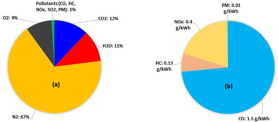
Figure 1. (a) Composition of exhaust gas from diesel engine; (b) Euro emissions standard for heavy duty vehicles.
For CO2 capture, amine absorption, membrane separation, cryogenic separation and adsorption are main technologies for post combustion CO2 capture from power plant and process industry. The amine absorption for capturing CO2 is commonly used in power plant and process industry including natural gas sweetening (Sharma et al., 2017). The amine absorption process is energy intensive: 3.6–4.0 MJ/kg using mono-ethanolamine and 2.0–3.8 MJ/kg using advanced amines, for 90% CO2 capture rate (Bui et al., 2018). For 90% CO2 capture, performance of amine absorption process and membrane process are similar with about 10% loss in the plant efficiency (Wang et al., 2017). For natural gas power plant with 85% CO2 capture using amine, efficiency of the integrated plant decreases by over 8% due to the energy penalty of CO2 capture (Tock and Maréchal, 2014). Amine absorption process is difficult to use in mobile applications, although it has been proposed in marine application (Luo and Wang, 2017). Pressure swing adsorption (PSA) is well established gas separation technology, which has found applications in air separation, hydrogen purification, and natural gas industry. Further, temperature swing adsorption (TSA) is an attractive technology for CO2 capture that requires low grade waste heat which may be available close to the CO2 emission source (See Figure 2). In a TSA cycle, cooled exhaust gases are passed through the adsorbent bed, where CO2 is adsorbed in the material and the remaining gases are released into the environment. Once adsorbent bed is saturated with CO2, it is heated to recover the CO2 from the material. After CO2 recovery from the adsorbent bed, it is cooled down from the desorption temperature to the adsorption temperature. Note that heat is removed during adsorption step, whereas heat is supplied during desorption step of a TSA cycle.
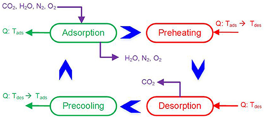
Figure 2. Simple schematic of TSA cycle with four steps. Q, Heat Supplied or Removed; Tads, Absorption Temperature; Tdes, Desorption temperature.
The temperature of engine exhaust normally range from 350 to 700°C (Dimitrova and Maréchal, 2017; Kanchibhotla and Bari, 2018). Further, the heat of cooling system can also be recovered as around 95°C (Abdelghaffar et al., 2002). The waste heat from engine exhaust and cooling system has been used in Rankine cycle to generate mechanical power for heavy duty trucks (Grelet et al., 2016) and cruise ships (Luo and Wang, 2017). Sprouse and Depcik (2013) have reviewed many studies on the use of organic Rankine cycle for the waste heat recovery from the exhaust of internal combustion engine, and claimed 10% improvement in the fuel economy. In order to overcome the dynamic nature of the engine waste heat availability, a heat storage material can be used to maintain the steady supply of heat to the Rankine cycle (Dinker et al., 2017). Lu et al. (2017) used a thermal fluid for the heat transfer between engine exhaust stream and working fluid of organic Rankine cycle, this mechanism is useful in maintaining steady operation of organic Rankine cycle.
The idea of the study is to investigate the possibility of integrating a Rankine cycle and a temperature swing adsorption system for vehicles. Proll et al. (2016) evaluated a fluidized bed TSA system for CO2 capture from flue gas stream, and in terms of heat transfer, fluidized bed reactor was found better than fixed, and moving bed reactors. Gibson et al. (2016) have evaluated several adsorption materials and process designs for CO2 capture from gas fired power plant. They have developed an adsorption model to predict the separation efficiency and to obtain the optimum separation conditions. Ntiamoah et al. (2016) performed cyclic experiments on single adsorption column, and product (hot) CO2 was used to supply the heat of desorption in the desorption step. In order to increase the purity of product CO2, they used product CO2 purge before the desorption step. Marx et al. (2016) studied cyclic behavior and separation performance of TSA for post-combustion CO2 capture. They performed break-through, heating and cooling, and steady-state cyclic experiments to evaluate separation performance of the process.
This work combines organic Rankine cycle with TSA to capture the CO2 from exhaust stream of an internal combustion engine. Amine doped adsorbents are selected for CO2 capture, as they show good performance in the presence of water (Huck et al., 2014). Part of the mechanical power produced by organic Rankine cycle is used to generate cold utility using CO2-based heat pump (turbo-compressor 1). This cold utility is used to remove heat of adsorption, and condense the water from engine exhaust stream. The remaining mechanical power generated by organic Rankine cycle is used to compress and liquefy the produced CO2 (turbo-compressor 2). The CO2 capture system has energy self-sufficiency, and does not require any external power. In other words, TSA with turbo-compressors is an attractive choice for CO2 capture from vehicles without any energy penalty. The CO2 capture system for engine exhaust stream aims at capturing 90% of the emitted CO2 (i.e., 2.11 kg CO2 per liter of diesel consumption). The captured CO2 can be utilized as a carbon source for producing green fuel (methane or liquid fuels) by integrating hydrogen produced from renewable energy resources.
Energy and Exergy Balance of Engine, TSA and CO2 Compression
Figure 3 describes the integrated CO2 capture system, based on 1 l diesel consumption in an internal combustion engine. First of all, diesel engine exhaust is analyzed for energy content and its composition. Figure 3 shows simple heat and mass flows for CO2 capture system. One liter diesel contains 37.27 MJ energy (lower heating value), which is divided into three parts by the internal combustion engine: 13.05 MJ as mechanical power to drive the vehicle, 14.21 MJ as waste heat in exhaust gas, and 10.02 MJ as heat removed using coolant (Hossain and Bari, 2014).
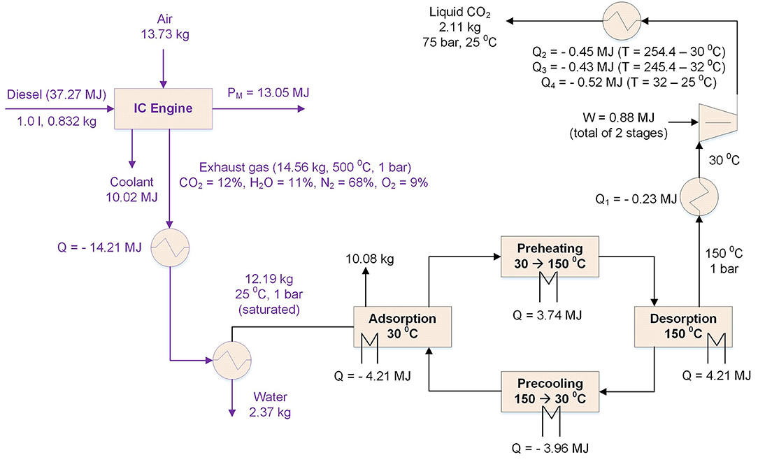
Figure 3. Simple heat and mass flows for CO2 capture from diesel engine exhaust: exhaust cooling, TSA cycle, product CO2 compression, and liquefaction.
The exhaust gas stream is cooled down to 25°C, and water is condensed and removed. The cooled exhaust gas stream (saturated with water at 25°C) goes to the adsorption bed, where CO2 is attached to the adsorbent. Finally, CO2 is desorbed from the adsorbent at high temperature, and then compressed and liquefied (multi-stage compression with inter-stage cooling). After desorption step, adsorbent bed is cooled down so that it can be used in the next TSA cycle. Belsim Vali models were developed for exhaust cooling and CO2 compression with inter-stage coolers. These models compute heat available from the exhaust stream at different temperature levels, and total compression power and inter-stage cooling requirements for CO2 compression. A TSA model was developed in gPROMS process simulator, based on the mathematical model shown in Table B of Supplementary Material (Casas et al., 2013). The TSA model has adsorption, preheating, desorption, and precooling steps. A mixture of N2 (84%) and CO2 (16%) was used to calculate heat of desorption, preheating of bed, heat of desorption and precooling of bed, at different adsorption, and desorption temperatures. The developed TSA model uses PPN-6-CH2TETA (Table C in Supplementary Material; Huck et al., 2014) as an adsorbent material. Finally, adsorption temperature of 30°C and desorption temperature of 150°C were chosen (see Figure A in Supplementary Material).
Figure 4 shows enthalpy-temperature profiles for exhaust cooling, heating and desorption of adsorbent, cooling and adsorption of adsorbent, and product CO2 compression and liquefaction. The exhaust stream contains 14.21 MJ/l-diesel waste heat, heating and desorption step requires 7.96 MJ/l-diesel heat, 8.17 MJ/l-diesel heat has to be removed during cooling and adsorption step, and 1.63 MJ/l-diesel heat has to be removed for CO2 compression and liquefaction.
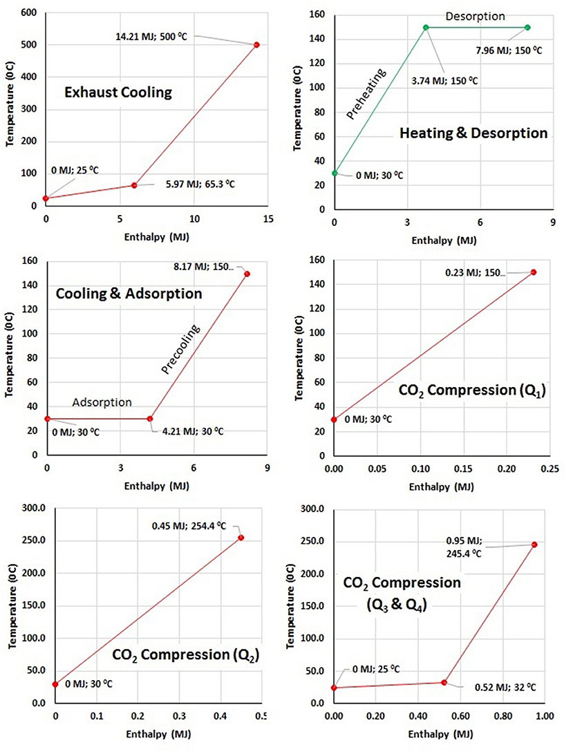
Figure 4. Enthalpy-temperature profiles for exhaust cooling, adsorption cooling, desorption heating and CO2 compression, and liquefaction for 1 l diesel.
Table 1 presents energetic and exergetic analyses of an internal combustion engine, TSA and CO2 compression and liquefaction (Al-Najem and Diab, 1992; Kul and Kahraman, 2016). The CO2 capture system design looks feasible from the exergetic point of view (Table 1 and Figure 5). In total, 3.04 MJ of net exergy is available. See the Supplementary Material for Exergy Calculations given in Table 1. In reality, this system is dynamic in nature due to exhaust variations and TSA cycle. The reported exergy analysis is for steady-state operation of the system which gives indication on the heat availability and heat requirements by the system. Assuming a 50% exergy efficiency, therefore there is a potential to produce the equivalent of 1.52 MJ of mechanical power for the CO2 capture and storage system. Assuming an isentropic efficiency of 75% for the compressors, this value can be compared with the compression power needed to produce CO2 in the liquid form (compression at 75 bar): 0.88 MJ or compressed CO2 at 150 bar: 1.05 MJ. For 1 l diesel consumption in an internal combustion engine, 2.11 kg CO2 is captured by the system, which has a volume of 2.96 l as liquid CO2 product (at 75 bar) or 4.53 l as compressed CO2 product (at 150 bar).
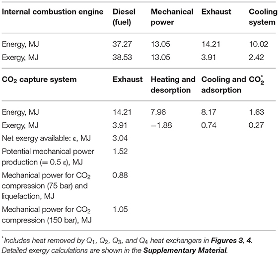
Table 1. Energy and exergy analyses of the internal combustion engine, the CO2 capture system, and compression power required for CO2 liquefaction (1 l diesel).
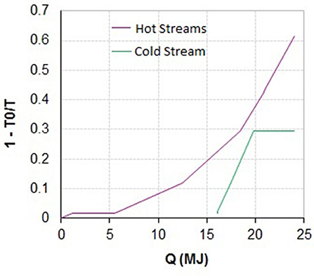
Figure 5. Q vs. 1-T0/T plot for CO2 capture system (1 l diesel); T0 (reference temperature) = 298 K.
Design of CO2 Capture Systems for a Delivery Truck
The preliminary exergy analysis shows that there is the opportunity by system integration to generate cold, heat, and work that is needed to capture the exhaust CO2 using the energy available in the exhaust gases. Referring to the usage in a mobile application, there is a need to generate cooling for adsorption step, and therefore production of cooling capacity is considered at a temperature lower than the 40°C. The overall system design concept combines exhaust cooling, TSA cycle, product CO2 compression and cooling, Rankine cycle and heat pumping, as shown in Figure 6.
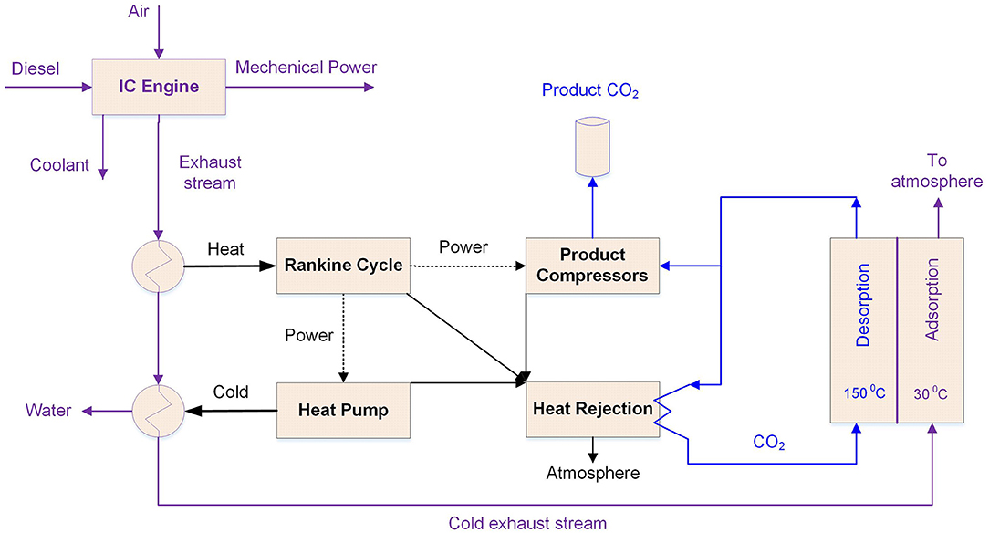
Figure 6. Overview of CO2 capture system design: integration of Rankine cycle (RC) and heat pump (HP).
The CO2 capture system is designed for 1 day operation of delivery truck in a city, which travels 250 km in 8 h (~20 l diesel/100 km, Delgado et al., 2017). The diesel engine emits 117.2 kg of CO2 by consuming 50 l diesel, and 105.5 kg of CO2 (90% capture) should be captured and stored by the CO2 capture system. The working capacity (or CO2 loading) of the adsorbent material is 0.1 kg-CO2/kg-adsorbent (Verdegaal et al., 2016). Finally, 1 h adsorption-desorption cycle time has been assumed (Gibson et al., 2016). Initially, three cases for CO2 capture system are analyzed, as summarized in Table 2.
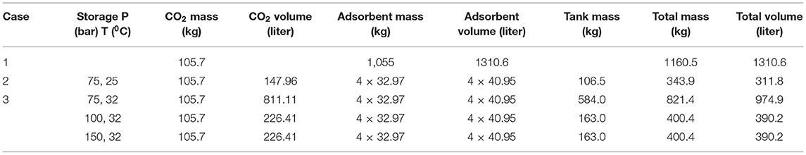
Table 2. Details of CO2 capture system specification (1 day operation, 250 km travel, 50 l diesel consumptions).
Adsorption on Truck and Desorption in the Parking Lot
In total, 105.5 kg of CO2 should be captured by the adsorbent. It requires 1055 kg of adsorbent, with CO2 loading of 0.1 kg-CO2/kg-adsorbent. Hence, the total mass of the system is 1160.5 kg. The density of adsorbent is 0.805 kg/liter, and so the volume of adsorbent or capture system is 1310.6 l. In the parking lot, CO2 can be converted into methane, and exothermic heat of methanation reaction can be used to recover CO2 from the adsorbent bed.
Adsorption-Desorption on Truck With CO2 Liquefaction (Liquid CO2)
In this case, CO2 is captured, compressed, liquefied, and stored in a storage tank. The critical point of CO2 is 31.1°C and 73.8 bar. In order to store liquid CO2 around 25°C in summer, an efficient cooling system would be required for operation of CO2 capture and storage system. The diesel engine consumes 6.25 l diesel per hour that means 13.19 kg CO2 should be captured per hour (1 l diesel = 2.34 kg CO2 emission, 90% CO2 capture, see Figure 3). Hence, the CO2 capture system requires 131.88 kg/h (163.8 l/h) of adsorbent. The duration of a TSA cycle is 1 h, and the regenerated adsorbent material can be used in the next TSA cycle. The estimated mass of storage tank is 273.6 kg to store 105.5 kg (or 147.96 l) liquid CO2 at 75 bar and 25°C (Turton et al., 2012). Further, typical weight of storage tank (modified CrMo steel) is 0.72 kg/liter for compressed natural gas at 200 bar (Ashok Leyland Report, 2012), and this light weight tank can also be used to store liquid or compressed CO2.
gPROMS model was developed for TSA cycle, whereas Belsim Vali models were developed for exhaust cooling, CO2 compression with inter-stage cooling, Rankine cycle and heat pump. CO2 based Rankine cycle (160 and 75 bar) is used to extract heat from the exhaust gas stream, and to produce the mechanical power in a turbine. This mechanical power is used in CO2 based heat pump (75 and 50 bar) to generate cold utility for removing heat of adsorption from bed and precooling of bed from desorption temperature to adsorption temperature. The lower pressure level for Rankine cycle and upper pressure level for heat pump are same (75 bar), so that streams from Rankine cycle and heat pump cycle can be combined for discharging waste heat into the environment. Figure 7 shows integrated operations of CO2 based Rankine cycle and heat pump. Further, heat rejected from CO2 based Rankine cycle is used for supplying heat of desorption and preheating of bed from adsorption temperature to desorption temperature. Finally, compressors are used to compress the product CO2 after the desorption step. The mechanical power generated using turbine is sufficient to run compressor for CO2 based heat pump and compressors for product CO2.
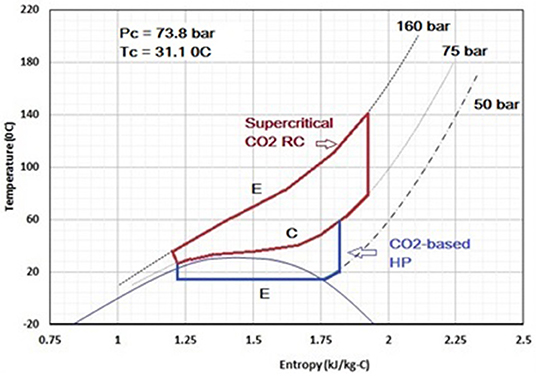
Figure 7. Integrated operation of CO2-based Rankine cycle (RC) and heat pump (HP).
In order to perform heat integration of the system, heat cascade model (Maréchal and Kalitventzeff, 1998) was used for heat integration among TSA cycle, exhaust cooling, inter-stage heat exchangers/coolers for CO2 compression, Rankine cycle, and heat pump. Figure 8 presents composite and grand composite curves for cooling of exhaust gas stream, heat of adsorption and precooling, heat of desorption and preheating, CO2 based Rankine cycle and heat pump, and product CO2 compression. In Figure 8, no external hot utility is required to close the heat balance which shows the feasibility of the CO2 capture system. The composite curves provides minimum energy targets (i.e., hot and cold utilities) that can be used in the heat exchanger network synthesis. Figure 9 presents a simple schematic of CO2 capture system design, without showing heat integration between hot and cold streams. In Figure 9, streams in red color show Rankine cycle operation, whereas streams in blue color show heat pump cycle operation. It can be seen that Rankine cycle and heat pump cycle streams are merged to discharge waste heat (RH1) into the environment. The product CO2 stream from desorption step is shown in green color, and it is compressed from 1 bar to 50 bar, before merging with heat pump cycle. The product CO2 is removed from the heat pump cycle at 75 bar and 30°C. Alternatively, a separate product CO2 compression and liquefaction system is also possible. The purity of product CO2 has been calculated using adsorbed phase CO2 and bulk phase gas mixture (i.e., cooled exhaust gas) inside the adsorption bed. The purity of product CO2 is about 99.5%, assuming 40% inter-particle empty space.
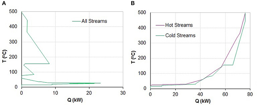
Figure 8. Grand composite (A) and composite (B) curves for the CO2 capture system.
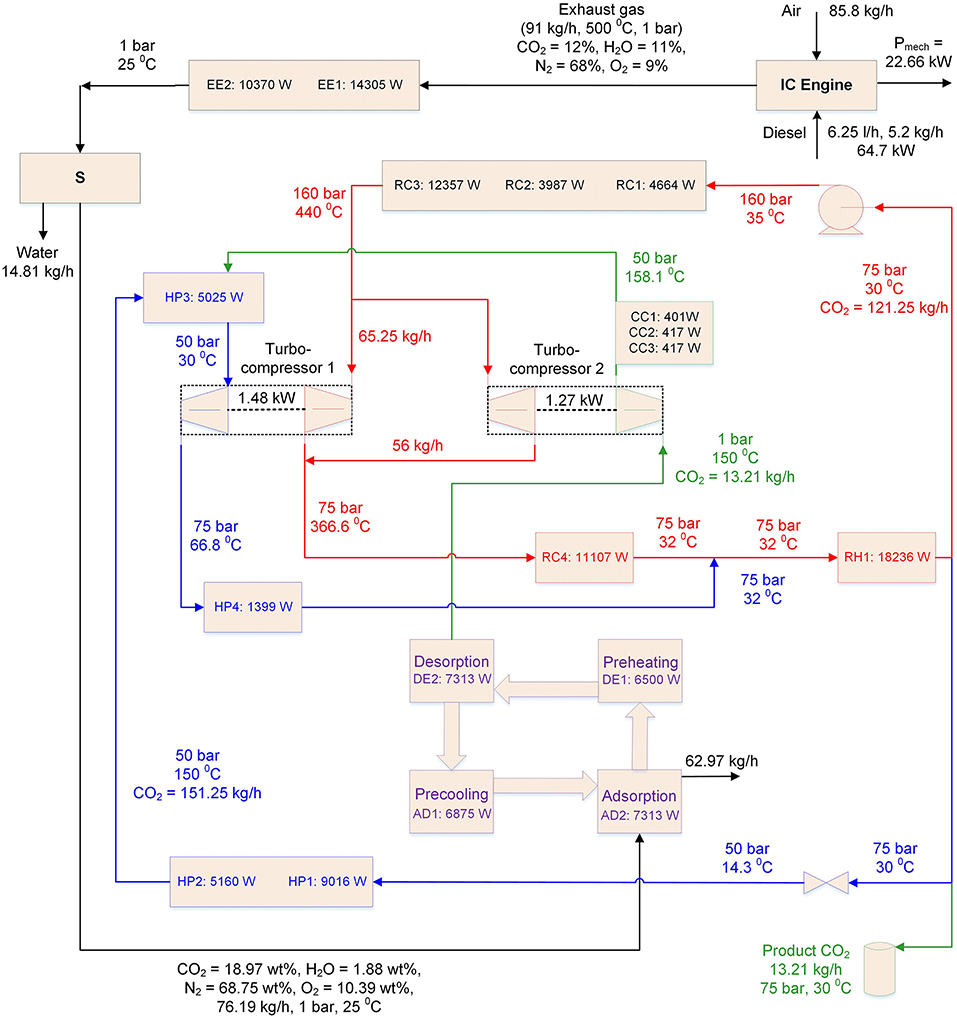
Figure 9. Heat and mass flow details of design of CO2 capture system (1 h operation or 6.25 l diesel consumptions).
In order to achieve the target temperatures of hot and cold streams with minimum utilities, hot and cold streams should exchange heat whenever possible. In this work, the heat exchanger network synthesis (stage-wise superstructure model) has been studied by mathematical programming method. For this, a mixed integer linear programming (MILP) optimization problem, written in AMPL, has been solved using CPLEX solver (Yee and Grossmann, 1990; Mian et al., 2016). In the optimization problem, minimization of number of heat exchangers is considered as objective function. There are 11 hot streams (AD1, AD2, EE1, EE2, RC4, RH1, HP3, HP4, CC1, CC2, and CC3) and 7 cold streams (DE1, DE2, RC1, RC2, RC3, HP1, and HP2) in the CO2 capture system. Table 3 presents heat exchanger network synthesis results, which has 20 heat exchangers. See Supplementary Material for grid representation of HEN. In Table 3, overall heat transfer coefficient (U) for a heat exchanger, with low heat transfer coefficients streams (exhaust cooling, precooling, adsorption, preheating and desorption), is assumed to be 25 W/(m2.K) (Clausse et al., 2011; Ribeiro et al., 2013; Marx et al., 2016). Further, the U-value for a heat exchanger, with high heat transfer coefficients streams (Rankine cycle, heat pump and cooling utility), is assumed to be 2000 W/(m2.K) (Yang, 2016). Finally, U-value of 500 W/(m2.K) is assumed for a heat exchanger with one low heat transfer coefficient stream and other high heat transfer coefficient stream. Table 3 presents estimated heat transfer areas for different heat exchanges, and AD1-DE1 heat exchanger (precooling and preheating of adsorption bed) has largest heat transfer area (11.23 m2). Total heat transfer area of all heat exchangers is 22.47 m2. More accurate heat exchanger area may be calculated by estimating overall heat transfer coefficients for different streams/heat exchangers. This heat transfer area can be provided in compact volume by using micro-channel heat exchangers, wherever it is possible (Hesselgreaves, 2001). TSA is a cyclic process with four steps, and so the heat exchangers inside the adsorbent beds should be heated and cooled in a cyclic way. Hence, heating and cooling of heat exchangers material will increase the thermal duty of the system.
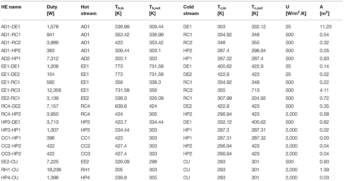
Table 3. Heat exchanger network synthesis for CO2 capture system.
Adsorption-Desorption on Truck With CO2 Compression (Compressed CO2)
In this case, product CO2 is compressed and stored at high pressure. The mass of compressed CO2 storage tank is much higher compared to the mass of storage tank for liquid CO2 (in Case 2). This case is suitable when compressed methane or natural gas is used as a fuel in the vehicle. Fuel tank for compressed fuel can also be used to store the compressed product CO2. Three pressures for storing compressed CO2 are considered: 75, 100, and 150 bar. It can be noted in Table 2 that compressed CO2 volume at 75 bar (811.11 l) is significantly larger when compared at 100 and 150 bar (226.41 l). The mass of storage tanks, for storing compressed CO2 at different pressures, are calculated as function of CO2 volume (0.72 kg/liter; Ashok Leyland Report, 2012). Compressed CO2 storage at 100 or 150 bar found to be better (lowest weight and volume) compared to 75 bar.
The CO2 capture system design in Case 2 (i.e., adsorption-desorption on truck with liquid CO2 product) is an attractive choice due to its lower weight and lower volume. For daily operation of a delivery truck, the total mass and volume of the adsorbent beds and captured CO2 with storage tank are about 343.9 kg and 311.8 l. Additionally, some weight and space will be required for piping, turbo-compressors and heat exchanger network. In general, about 2 m3 space is available over the truck cabin (www.uhaul.com). Hence, temperature swing adsorption based CO2 capture system can easily be placed over the truck cabin. Figure C in Supplementary Material presents estimated volume of CO2 capture and storage system for delivery truck. The CO2 storage tank can be placed below the truck cabin, so that it can easily be removed and replaced.
Green Fuel Production and Use of Alternate Fuels
The captured CO2 by the system can be sequestrated in underground or used as feedstock to produce gas or liquid green fuels and chemicals. Conversion of CO2 into chemicals is a good option from economic perspective due to their high prices (Chen et al., 2018). Table D (in Supplementary Material) presents the conversion of 1 kg of CO2 into green fuel by co-electrolysis (solid oxide electrolysis cell) using renewable electricity (Wang et al., 2018). The renewable electricity for CO2 conversion into green fuels can be provided by the PV panels. For calculating total area of PV panels in Switzerland, 400 W/m2 average annual solar irradiation (17.28 MJ/day/m2; www.meteoswiss.admin.ch) has been considered in Table D (Supplementary Material). Further, solar irradiation to electricity conversion efficiency of 20% has been assumed for the PV panels.
The delivery truck consumes 50 l (41.6 kg) diesel for 250 km travel, or 1,885 MJ energy based on the lower heating value of diesel fuel. Assuming same efficiency of the engine for different fuels, Table 4 presents amount of alternate fuels used, CO2 produced, CO2 captured, fuel produced using captured CO2, renewable energy consumed, and PV panel area. The fuel produced / fuel used ratio is different for different carbon based green fuels. In Table 4, H2 fuel is also reported for comparison purpose. The efficiency of electrolysis (electricity to H2) is assumed to be 80% (Schaaf et al., 2014), H2 efficiency in the internal combustion engine is considered same as for diesel engine (Verhelst and Wallner, 2009). In order to use H2 in existing internal combustion engine, fuel supply system has to be modified to avoid pre-ignition in the premixed H2 and air (Salvi and Subramanian, 2015). Further, high NOx emission has been reported for H2 in spark ignition engine due to increase in combustion temperature (Shivaprasad et al., 2018). Figure 10 presents weight of fuel with storage tank and CO2 capture system with liquid CO2 storage, for different fuels. For compressed CH4 fuel, it is assumed that captured CO2 can be stored in the same storage tank. For different fuels, the total weight (fuel with storage tank, adsorbent material, and CO2 with storage tank) are compared at initial point (0 km), mid-point (125 km), and end point (250 km). For carbon based fuels, added weights of fuel and CO2 capture and storage systems are comparable.
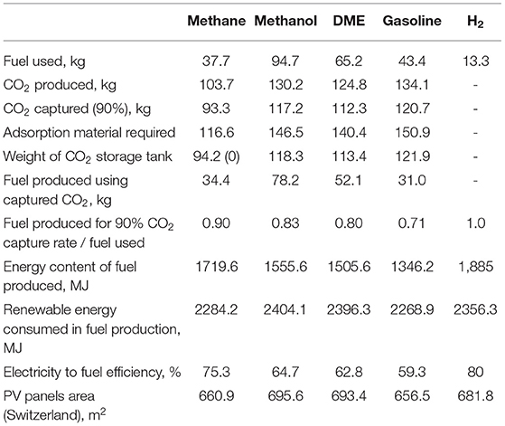
Table 4. Use of alternate fuels in the delivery truck for 250 km travel.
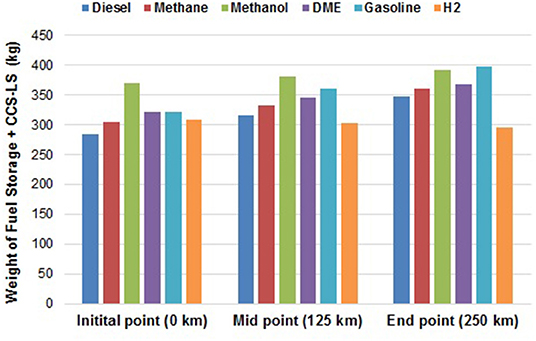
Figure 10. Weight comparison between on-board storage of H2 and different carbon based fuels with CCS-LS for conventional internal combustion engine.
CO2 Capture System and Liquid Storage for Different Vehicles
The CO2 capture system and liquid storage (CCS-LS) can be integrated on different types on vehicles such as cars, trucks, buses, ships, and trains. Average weights, payloads and fuel (diesel) consumptions for different types of vehicles are reported in the Supplementary Material (Table E). The added weight of CCS-LS includes weights of CO2 with storage tank and adsorbent material. For comparison basis, each vehicle is assumed to be traveled 250 km (diesel fuel), and travel time for each vehicle is reported in the Supplementary Material (Table F). Figure 11 presents percentage added weight of CCS-LS with respect to total weight of vehicle (i.e., empty weight of vehicle + payload on vehicle) and payload on vehicle. For ferry and cruiseship, payloads are estimated based on maximum number of on-board persons. As expected, percentage added weight of CCS-LS is larger for small vehicles (car, SUV) compared to large vehicles (ferry, cruiseship, train). CCS-LS can be used on vehicle to reduce the CO2 emissions by allowing a higher share of renewables used in the transport and reducing the fossil CO2 emissions to environment and the same time to generate cooling by using waste heat available in the engine exhaust stream and cooling system.
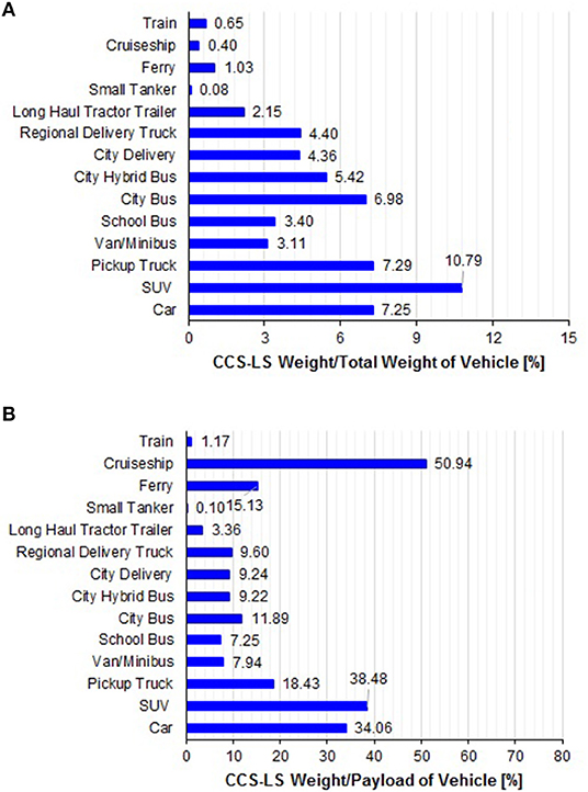
Figure 11. Percentage added weight of CO2 capture system and liquid storage (CCS-LS) with respect to total weight (A) and payload (B) of different vehicles.
Conclusions and Future Works
This study presents a system for CO2 capture from the exhaust stream of an internal combustion engine. Energy and exergy analyses of the CO2 capture system has been performed in details. Three CO2 capture system designs have been compared, and adsorption-desorption on vehicle with liquid CO2 product found to be better than the other two designs. The system design includes integration of temperature swing adsorption, Rankine cycle, heat pump (i.e., cold generation), and CO2 compression and liquefaction on vehicle. The proposed system design has energy self-sufficiency, as it converts waste heat available in the exhaust stream into mechanical power (via Rankine cycle) to drive the heat pump compressor and product compressors. The captured CO2 can store renewable energy by converting product CO2 into green fuels using co-electrolysis. About 90% of the carbon present in the fuel can be recycled using CO2 capture system, and the remaining 10% carbon can be supplied from the biomass. This study compares conversion of captured CO2 into methane, methanol, DME and gasoline. Further, percentage added weights of CO2 capture system and liquid storage for several vehicles are calculated, that shows high potential for the integration of CO2 capture in the transportation sector. Finally, weights of on-board hydrogen storage for fuel cell electric vehicle and CO2 capture system with liquid storage for conventional diesel vehicle are compared.
This study is an initial effort for capturing CO2 from vehicles, and it may require several years to realize such system in practice. In this study, fixed composition and flow rate of the exhaust gas have been assumed, to calculate the heating/cooling requirements of the TSA. This choice is suitable for train and ship transports, but exhaust variations are expected for cars, trucks, and buses. Further, steady-state operation of Rankine cycle is very critical, and so an intermediate thermal fluid will be required to store the exhaust heat and to maintain the Rankine cycle operation. In future, dynamic study on the system will be performed. This system analysis and design have several assumptions and uncertainties, which should be improved by experimental data. Hence, we are planning to develop a prototype of the CO2 capture system.
Data Availability Statement
The raw data supporting the conclusions of this manuscript will be made available by the authors, without undue reservation, to any qualified researcher.
Author Contributions
All authors listed have made a substantial, direct and intellectual contribution to the work, and approved it for publication.
Conflict of Interest
The authors declare that the research was conducted in the absence of any commercial or financial relationships that could be construed as a potential conflict of interest.
Acknowledgments
This research project is financially supported by the Swiss Innovation Agency lnnosuisse and is part of the Swiss Competence Center for Energy Research SCCER EIP.
Supplementary Material
The Supplementary Material for this article can be found online at: https://www.frontiersin.org/articles/10.3389/fenrg.2019.00143/full#supplementary-material
References
Abdelghaffar, W. A., Osman, M. M., Saeed, M. N., and Abdelfatteh, A. I. (2002). “Effects of coolant temperature on the performance and emissions of a diesel engine,” in Asme Internal Combustion Engine Division Spring Technical Conference (Rockford, IL), 187–197. doi: 10.1115/ICES2002-464
Al-Najem, N. M., and Diab, J. M. (1992). Energy-exergy analysis of a diesel engine. Heat Recov. Syst. CHP 12, 525–529. doi: 10.1016/0890-4332(92)90021-9
Ashok Leyland Report (2012). Report on CNG Cylinders for Automotive Vehicle Applications. Chennai: Product Development Ashok Leyland Technical Centre.
Bui, M., Adjiman, C. S., Bardow, A., Anthony, E. J., Boston, A., Brown, S., et al. (2018). Carbon capture and storage (CCS): the way forward. Energy Environ. Sci. 11, 1062–1176. doi: 10.1039/C7EE02342A
Casas, N., Schell, J., Joss, L., and Mazzott, M. (2013). A parametric study of a PSA process for pre-combustion CO2 capture. Sep. Purif. Technol. 104, 183–192. doi: 10.1016/j.seppur.2012.11.018
Chen, C., Kotyk, J. F. K., and Sheehan, S. W. (2018). Progress toward commercial application of electrochemical carbon dioxide reduction. Chem 4, 2571–2586. doi: 10.1016/j.chempr.2018.08.019
Clausse, M., Merel, J., and Meunier, F. (2011). Numerical parametric study on CO2 capture by indirect thermal swing adsorption. Int. J. Greenhouse Gas Control 5, 1206–1213. doi: 10.1016/j.ijggc.2011.05.036
Delgado, O., Rodriguez, F., and Muncrief, R. (2017). Fuel Efficiency Technology in European Heavy-Duty Vehicles: Baseline and Potential for the 2020–2030 Time Frame. Berlin: The International Council on Clean Transportation.
Dimitrova, Z., and Maréchal, F. (2017). Energy integration on multi-periods for vehicle thermal powertrains. Can. J. Chem. Eng. 95, 253–264. doi: 10.1002/cjce.22588
Dinker, A., Agarwal, M., and Agarwal, G. D. (2017). Heat storage materials, geometry and applications: a review. J. Energy Inst. 90, 1–11. doi: 10.1016/j.joei.2015.10.002
European Environment Agency (2017). National Emissions Reported to the UNFCCC and to the EU Greenhouse Gas Monitoring Mechanism. Copenhagen: Directorate-General for Environment, United Nations Framework Convention on Climate Change.
Gibson, J. A. A., Mangano, E., Shiko, E., Greenaway, A. G., Gromov, A. V., Lozinska, M. M., et al. (2016). Adsorption materials and processes for carbon capture from gas-fired power plants: AMPGas. Ind. Eng. Chem. Res. 55, 3840–3851. doi: 10.1021/acs.iecr.5b05015
Grelet, V., Reiche, T., Lemort, V., Nadri, M., and Dufour, P. (2016). Transient performance evaluation of waste heat recovery rankine cycle based system for heavy duty trucks. Appl. Energy 165, 878–892. doi: 10.1016/j.apenergy.2015.11.004
Hebbar, G. S. (2014). NOx from diesel engine emission and control strategies-a review. Int. J. Mech. Eng. Rob. Res. 3, 471–482. Available online at: http://www.ijmerr.com/uploadfile/2015/0409/20150409042911754.pdf
Hesselgreaves, J. E. (2001). Compact Heat Exchangers, Selection, Design and Operation. Pergamon: Elsevier Ltd.
Hossain, S. N., and Bari, S. (2014). Waste heat recovery from exhaust of a diesel generator set using organic fluids. Procedia Eng. 90, 439–444. doi: 10.1016/j.proeng.2014.11.753
Huck, J. M., Lin, L. C., Berger, A. H., Shahrak, M. N., Martin, R. L., Bhown, A. S., et al. (2014). Evaluating different classes of porous materials for carbon capture. Energy Environ. Sci. 7, 4132–4146. doi: 10.1039/C4EE02636E
IPCC (2014). Climate Change 2014: Mitigation of Climate Change. Contribution of Working Group III to the Fifth Assessment Report of the Intergovernmental Panel on Climate Change. Cambridge: Cambridge University Press.
Kanchibhotla, S. A., and Bari, S. (2018). Optimum Design Point to Recover Maximum Possible Exhaust Heat Over the Operating Range of a Small Diesel Truck Using Bottoming Rankine Cycle. Warrendale, PA: SAE International, SAE Technical Paper 2018-01-1377.
Kul, B. S., and Kahraman, A. (2016). Energy and exergy analyses of a diesel engine fuelled with biodiesel-diesel blends containing 5% bioethanol. Entropy 18:387. doi: 10.3390/e18110387
Ligterink, N. E., van Zyl, P. S., and Heijne, V. A. M. (2016). Dutch CO2 Emission Factors for Road Vehicles. Utrecht: TNO R10499.
Lu, Y., Roskilly, A. P., Smallbone, A., Yu, X., and Wang, Y. (2017). Design and parametric study of an organic Rankine cycle using a scroll expander for engine waste heat recovery. Energy Procedia 105, 1420–1425. doi: 10.1016/j.egypro.2017.03.530
Luo, X., and Wang, M. (2017). Study of solvent-based carbon capture for cargo ships through process modelling and simulation. Appl. Energy 195, 402–413. doi: 10.1016/j.apenergy.2017.03.027
Majewski, W. A., and Khair, M. K. (2006). Diesel Emissions and Their Control. Warrendale, PA: SAE International. doi: 10.4271/R-303
Maréchal, F., and Kalitventzeff, B. (1998). Process integration: selection of the optimal utility system. Comp. Chem. Eng. 22, 149–156. doi: 10.1016/S0098-1354(98)00049-0
Marx, D., Joss, L., Hefti, M., and Mazzotti, M. (2016). Temperature swing adsorption for post-combustion CO2 capture: Single- and multicolumn experiments and simulations. Ind. Eng. Chem. Res. 55, 1401–1412. doi: 10.1021/acs.iecr.5b03727
Mian, A., Martelli, E., and Maréchal, F. (2016). Framework for the multiperiod sequential synthesis of heat exchanger networks with selection, design, and scheduling of multiple utilities. Ind. Eng. Chem. Res. 55, 168–186. doi: 10.1021/acs.iecr.5b02104
Ntiamoah, A., Ling, J., Xiao, P., Webley, P. A., and Zhai, Y. (2016). CO2 capture by temperature swing adsorption: use of hot CO2-rich gas for regeneration. Ind. Eng. Chem. Res. 55, 703–713. doi: 10.1021/acs.iecr.5b01384
Proll, T., Schony, G., Sprachmann, G., and Hofbauer, H. (2016). Introduction and evaluation of a double loop staged fluidized bed system for post-combustion CO2 capture using solid sorbents in a continuous temperature swing adsorption process. Chem. Eng. Sci. 141, 166–174. doi: 10.1016/j.ces.2015.11.005
Ribeiro, R. P. P. L., Grande, C. A., and Rodrigues, A. E. (2013). Activated carbon honeycomb monolith – Zeolite 13X hybrid system to capture CO2 from flue gases employing electric swing adsorption. Chem. Eng. Sci. 104, 304–318. doi: 10.1016/j.ces.2013.09.011
Salvi, B. L., and Subramanian, K. A. (2015). Sustainable development of road transportation sector using hydrogen energy system. Renew. Sust. Energy Rev. 51, 1132–1155. doi: 10.1016/j.rser.2015.07.030
Schaaf, T., Grunig, J., Schuster, M. R., Rothenfluh, T., and Orth, A. (2014). Methanation of CO2 - storage of renewable energy in a gas distribution system. Energy Sust. Soc. 4:2. doi: 10.1186/s13705-014-0029-1
Sharma, S., Rangaiah, G. P., and Maréchal, F. (2017). “Integrated multi-objective differential evolution and its application to amine absorption process for natural gas sweetening,” in Differential Evolution in Chemical Engineering: Developments and Applications, eds G. P. Rangaiah and S. Sharma (Singapore: World Scientific), 128–155. doi: 10.1142/9789813207523_0005
Shivaprasad, K. V., Rajesh, R., Anteneh Wogasso, W., Nigatu, B., and Addisu, F. (2018). Usage of hydrogen as a fuel in spark ignition engine. Mater. Sci. Eng. 376:012037. doi: 10.1088/1757-899X/376/1/012037
Sprouse, C. III, and Depcik, C. (2013). Review of organic Rankine cycles for internal combustion engine exhaust waste heat recovery. Appl. Ther. Eng. 51, 711–722. doi: 10.1016/j.applthermaleng.2012.10.017
Tock, L., and Maréchal, F. (2014). Process design optimization strategy to develop energy and cost correlations of CO2 capture processes. Comp. Chem. Eng. 61, 51–58. doi: 10.1016/j.compchemeng.2013.10.011
Turton, R., Bailie, R. C., Whiting, W. B., and Shaeiwitz, J. A. (2012). Analysis, Synthesis and Design of Chemical Processes, 4th Edn. New Jersey, NJ: Prentice Hall.
United States Environmental Protection Agency (2016). Inventory of U. S. greenhouse gas emissions and sinks: 1990–2016, EPA 430-R-18-003.
Verdegaal, W. M., Wang, K., Schulley, J. P., Wriedt, M., and Zhou, H.-C. (2016). Evaluation of metal-organic frameworks and porous polymer networks for CO2-capture applications. ChemSusChem 9, 636–643. doi: 10.1002/cssc.201501464
Verhelst, S., and Wallner, T. (2009). Hydrogen-fueled internal combustion engines. Progress Energy Comb. Sci. 35, 490–527. doi: 10.1016/j.pecs.2009.08.001
Wang, L., Perez-Fortes, M., Madi, H., Diethelm, S., Herle, J. V., and Maréchal, F. (2018). Optimal design of solid-oxide electrolyzer based power-to-methane systems: a comprehensive comparison between steam electrolysis and co-electrolysis. Appl. Energy 211, 1060–1079. doi: 10.1016/j.apenergy.2017.11.050
Wang, Y., Zhao, L., Otto, A., Robinius, M., and Stolter, D. (2017). A review of post-combustion CO2 capture technologies from coal-fired power plants. Energy Procedia 114, 650–665. doi: 10.1016/j.egypro.2017.03.1209
Yang, M. (2016). Numerical study on the heat transfer of carbon dioxide in horizontal straight tubes under supercritical pressure. PLoS ONE 11:e0159602. doi: 10.1371/journal.pone.0159602
Keywords: carbon dioxide capture, internal combustion engine, exergy analysis, temperature swing adsorption, system design and integration, heat exchanger network
Citation: Sharma S and Maréchal F (2019) Carbon Dioxide Capture From Internal Combustion Engine Exhaust Using Temperature Swing Adsorption. Front. Energy Res. 7:143. doi: 10.3389/fenrg.2019.00143
Received: 16 May 2019; Accepted: 18 November 2019;
Published: 16 December 2019.
Edited by:
Fateme Rezaei, Missouri University of Science and Technology, United StatesReviewed by:
Jenny G. Vitillo, Università dell'Insubria, ItalyLisa Joss, University of Manchester, United Kingdom
Copyright © 2019 Sharma and Maréchal. This is an open-access article distributed under the terms of the Creative Commons Attribution License (CC BY). The use, distribution or reproduction in other forums is permitted, provided the original author(s) and the copyright owner(s) are credited and that the original publication in this journal is cited, in accordance with accepted academic practice. No use, distribution or reproduction is permitted which does not comply with these terms.
*Correspondence: François Maréchal, ZnJhbmNvaXMubWFyZWNoYWxAZXBmbC5jaA==
†These authors have contributed equally to this work