 Maruf A. Aminu
- Department of Electrical Engineering, Waziri Umaru Federal Polytechnic, Birnin Kebbi, Nigeria
Energy theft through meter bypass by residential consumers constitutes significant revenue loss to electric power distribution companies. This unpleasant phenomenon is particularly worrisome in sub-Saharan Africa and some parts of Asia. This paper reports the outcome of a study that attempts to develop a modified distribution and metering system to demotivate energy theft by residential consumers. The project involves modeling and simulating a 5-Hz distribution system in SimPowerSystems. The developed system is then implemented using laboratory-scale power electronics components. The modified distribution system is thereafter interfaced with a modified digital consumer energy meter. The system is subsequently tested by deploying it to power two categories of lighting loads. The test results show that one category of lighting load flickers while the other category is non-operational whenever the proposed system is bypassed, though the power remains available. This is expected to demotivate the practice of energy theft through meter bypass. Thus, it is further expected that the proposed system will mitigate revenue loss by power distribution companies, thereby stimulating investments in the sub-sector.
Introduction
The development of poor countries like Nigeria has been hampered by electricity shortage (Golden and Min, 2011). One of the problems preventing the development of the electricity sub-sector in Nigeria is the history of the nation, which sees it emerging from a mentality that views electricity as a non-tangible item with worthless value. Until recently, many Nigerians did not see electricity theft as a crime against the provider of the commodity as well as a crime against other consumers. Under the law, electricity theft is punishable in Nigeria (Garba and Akpeneye, 2017; Adeniran, 2018; Akamihe et al., 2018).
In 2008, the World Bank Group (WBG) draft report, which describes the performance of utilities in sub-Saharan countries, revealed huge inefficiencies. According to the report, only 50 percent of the electricity generated is paid for due to a number of factors, including low rates of revenue collection. The report indicates significant variation in performance, with the highest inefficiencies in Nigeria, where the utility is capturing only 25 percent of the revenues owed: “Some recent studies have shown that hidden costs of distribution losses in sub-Saharan Africa are usually more than 0.5 percent of GDP, and may be as large as 1.2 percent of GDP in some countries” (Antmann, 2009). For a long time, electrical energy has been illegally consumed by residential, commercial, and industrial customers in developing countries. On one hand, this has contributed to reducing the useful life of the system. On the other hand, it has contributed to massive revenue loss to system operators (Seger and Icove, 1988). This menace is less observed among industrial consumers, but it could be severe when it takes place among this class of consumers (Golden and Min, 2011). This is, perhaps, attributable to the fact that industrial consumers are highly supervised. Energy theft is usually more rampant among residential consumers (Saikiran and Hariharan, 2014). As reported in literature, a number of efforts have been made to curtail or prevent this unwanted phenomenon.
In 2009, P. Antmann prepared a paper for the World Bank Group energy sector strategy (Antmann, 2009). The paper advocates for the use of pre-paid energy meters for electricity distribution. The meters advocated in the paper are based on Advanced Metering Infrastructure (AMI), which is currently in use in Nigeria. The World Bank Group energy sector believes that, since the bypass of these meters can be detected by the distribution company (DISCO), energy consumers are shamed when detected and this discourages potential energy theft (Antmann, 2009). This is probably true in some countries but may not represent the reality in Nigeria. In Nigeria, these meters still leave the DISCOs vulnerable to revenue loss (Enwere et al., 2016; Oladejo, 2017).
In 2012, Omijeh et al. proposed an intelligent power theft detection model for prepaid energy metering in Nigeria (Omijeh et al., 2012). The proposed meter model is based on GSM communication. It monitors the total consumption of a group of consumers and compares it with a preset reference. Upon violation of the set ratio, energy theft is detected, and a theft alert is sent to the DISCO. This proposal appears novel but is obviously associated with several drawbacks in addition to the fact that it is vulnerable to bypass by consumers. Firstly, it is based on third-party communication. This makes the model unreliable since communication links are vulnerable to failures. A second deficiency of this proposal is that it requires frequent re-calibration. This is because consumer population as well as the appetite for electricity always grows, resulting in increasing demand for electricity (Aminu, 2016).
In 2015, Dike et al. proposed a GSM-based energy meter to minimize household electricity theft in Nigeria (Dike et al., 2015). Its principle of operation is essentially similar to the proposal by Omijeh et al. (2012), and it thus suffers similar drawbacks.
In 2015, Uzedhe and Ofualagba published a paper that proposed a multi-channel energy meter for grouped residential consumers (Uzedhe and Ofualagba, 2015). Their proposal is based on channel splitting using a microcontroller. The proposed meter is limited to only one class of residential consumers that are grouped on a single meter and have potential for dispute over payment contribution. It does not solve the problem of energy theft since a group of consumers could collude to bypass the proposed meter, and the meter itself is vulnerable to bypass.
Several concepts for solving the problem of energy theft by electricity consumers have been reported in literature, but the reported proposals suffer from vulnerability to consumer behavior. This is aggravated when DISCO personnel are involved in collusion with consumers.
The Head of the Revenue Protection Department of Port Harcourt Electricity Distribution Company was quoted as saying, “We are losing N=238bn monthly to theft”, those were the words of the Head” (Ekpimah, 2016). This is not an isolated case. The situation requires an urgent solution through minimal human interference. Such a solution is a system that ensures that consumers do not enjoy the service if they bypass the meter, and this is proposed in this report. This report proposes a plug-and-play modification to the existing distribution system so that consumers are free to bypass their meters but do not enjoy the service whenever they bypass their meters.
This work makes two direct and one indirect contribution to relevant scholarship:
(i) Proposal of a modified power distribution network that helps mitigate energy theft by residential consumers;
(ii) Proposal of a modified power distribution network with potential to improve revenue collection of power distribution companies in Nigeria and sub-Saharan Africa.
By extension, this work indirectly contributes to a proposal for a power distribution network that has the potential to provide relief for the distribution network since customers who normally bypass energy meters and overstress the network through use of high-power and inefficient electrical appliances are likely to be prudent in their use of electricity.
Consequently, the researcher hopes that this work shall contribute to efforts aimed at reducing energy theft through meter bypass, increasing the useful life of the system, increasing revenue accruable to DISCOs, and increasing the potential for sustainable electricity supply by DISCOs in Nigeria and beyond.
Description of the Proposed 5-Hz Distribution System
The 5-Hz distribution system is inspired by the theory of persistence of vision. When an event occurs at a rate that is greater than (or equal to) 15 repetitions per seconds, it appears persistent to the normal human vision (McKinney, 2008). The response (effect) received by a user of household electrical (or electronic) appliances is dependent on the frequency of the input signal. Excitation of the circuitry is therefore inadequate if the appropriate signal frequency is not supplied. This results in over-excitation or under-excitation if the signal frequency is higher or lower than the nominal range, respectively (Hart, 2011).
In addition to over-excitation and unpleasant consumer effects, higher frequencies result in increased power losses within the appliance and associated components. Lower frequencies result in reduced power loss, under-excitation, and unpleasant consumer effects as given by Equation (1). Thus, parameter variation by lowering the frequency is favored in this work. In line with the theory of persistence of vision, reducing the power signal frequency sufficiently below 15-Hz eliminates its persistence to the normal human vision. In Nigeria, the supply frequency is 50-Hz. Arbitrarily reducing the supply frequency to one-tenth of nominal frequency ensures sufficiently low frequency. Applying this reduced frequency of supply to household electrical appliances leads to reduced power loss, under-excitation, and a non-persistence of response of consumer appliances, such as unpleasant flickering of lighting appliances. It could also result in an outright non-response of some lighting and non-lighting appliances. Using analogous logic, it is expected that other electronic circuitries are unable to receive appropriate excitation and consequently become non-responsive.
The proposed system involves the deployment of 50 to 5-Hz frequency converters (called down-frequency converters in Figure 1A) as an add-on to the contemporary distribution system. The proposed add-on network is realized using requisite power electronics components so that it connects the consumer's appliance to the contemporary distribution system, as depicted in Figure 1A.
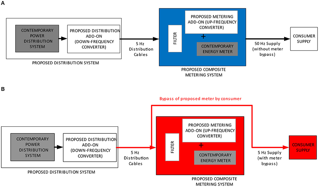
Figure 1. Block diagram of the proposed system: (A) without bypass of proposed meter; (B) with bypass of proposed meter.
The proposed metering system integrates 5 to 50-Hz frequency converters (called up-frequency converters in Figure 1A) to the contemporary energy meter as well as input filter network. The up-frequency converter circuit is embedded on the same printed circuit board (PCB) as the contemporary Watt-hour prepaid meter to inhibit access to the internal circuitry by users, thereby preventing possible access to terminals of the up-frequency converter by consumers.
Bypass of the proposed composite meter is depicted in Figure 1B. When a consumer bypasses the proposed composite meter, the consumer receives a 5-Hz power supply. This supply is inappropriate for excitation of typical household appliances, resulting in poor or non-response of consumer appliances. This poor or non-response of consumer appliances demotivates further bypass of the proposed composite meter, mitigating energy theft by residential consumers.
The proposed system is split into two parts: one part is added to the contemporary distribution substation while the other part is added to the metering asset (Figure 1A). At the output of the distribution transformer, a down-frequency converter is added to step down the power frequency from 50 to 5-Hz. The unfiltered 5-Hz power signal is passed to the consumer's premise through 5-Hz distributors. The distributors connect the unfiltered 5-Hz substation to the consumer's proposed metering asset, as shown in Figure 1A. The proposed meter consists of composite input filter, contemporary Watt-hour meter and an up-frequency converter. The up-frequency converter steps up the 5-Hz power signal to 50-Hz to service the consumer. The composite meter circuits are printed onboard so that the consumer is unable to separate the circuit blocks.
Description of Electrical Loads
Electrical Load Modeling
Electrical appliances are usually described as electrical load models (Collin et al., 2014). The power demanded by an electrical load is a function of both the native load characteristics and the input supply. Generally, all electrical loads can be categorized on the basis of supply voltage magnitude:
(i) Constant power load—this category of loads demands constant power from the supply regardless of the supply voltage. If the supply voltage drops, it draws more currents in order to demand constant power from the supply system.
(ii) Constant current load—this category of loads demands a constant current from the supply regardless of the supply voltage. If the supply voltage drops, the power it draws from the supply system drops proportionately.
(iii) Constant impedance load—in this category of loads, the active and reactive power demands vary proportionately to the square of the supply voltage magnitude.
Modern loads are non-linear and are therefore more accurately represented by a mixture of the three general categories. The relationship describing this static non-linear load model is presented in Equation (1) for active power and in Equation (2) for reactive power (Tsagarakis et al., 2013).
where,
P = active power demand, Po = rated active power;
Q = reactive power demand, Qo = rated reactive power;
V = supply voltage, Vo = rated voltage;
Zp, Ip, Pp, and Zq, Iq, Pq are the polynomial load model coefficients.
Parametric Load Description
Electrical loads can be categorized on the basis of their native impedance. The impedance is a summation of resistance, inductive reactance, and capacitive reactance. The three basic classifications on the basis of impedance are resistive loads, inductive loads, and capacitive loads. These classes of loads differ in the manner in which they consume power from alternating sources. Their responses to alternating sources also differ. Resistive, inductive, and capacitive loads correspond to heating, mechanical, and lighting loads, respectively (Beck, 2018).
Resistive Loads
These loads consist of heating elements. They are found in residential premises and include incandescent lights, toasters, ovens, space heaters, and coffee makers.
Inductive Loads
These loads consist of electrical motors. They are found in various household items with moving parts. They include fans, vacuum cleaners, washing machines, dishwashers, and compressors in both refrigerators and air conditioners.
Capacitive Loads
Practically, this category of loads does not exist in isolation. Capacitive loads do not exist in the same manner as resistive or inductive. Rather, capacitance exists as part of either resistive or inductive loads.
Distribution Network Modeling
The model presented assumes a balanced three-phase system and implements a one-phase distributed parameter line with lumped losses (Figure 2). The model is based on Bergeron's traveling wave method as used by Electromagnetic Transient Programs (EMTP). The model is used since it supports attenuation of high frequencies. Due to skin effects in the conductors and ground, the R and L matrices exhibit strong dependence on frequencies, thereby causing the attenuation of signals with high frequencies. In comparison to the π-section line model, the distributed line represents wave propagation phenomena and line end reflections with much better accuracy (Dommel, 1969).
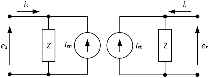
Figure 2. Two-port model of a single-phase distribution line.
The lossless distributed line in this model is characterized by two values (for a single-phase line): the surge impedance (Zc) and the wave propagation speed (v), presented in Equations (3) and (4).
where l and c are the per-unit length inductance and capacitance respectively.
For a lossless line (r = 0), the quantity e + Zci must arrive unchanged at the other end after a transport delay τ, where e is the line voltage at one end and i is the line current entering the same end.
where d is the line length.
The model voltage Equations for a lossless line are presented in Equations (6) and (7).
The current Equations are given in Equations (8) and (9).
The two current sources Ishand Irh in a lossless line are modeled as in Equations (10) and (11).
In practical systems, losses are not neglected, and new model Equations for Ish and Irh are thus obtained by lumping R/4 at both ends of the line and R/2 in the middle of the line as presented in Equation (13).
where R is the total line resistance.
The current sources Ish and Irh are then recomputed as presented in Equations (13) to (18).
where r, l, c are the per unit length parameters and d is the line length in meter. For a lossless line, r = 0, h = 1, and Z = ZC.
Converter Modeling
Figure 3 shows the schematic diagram of the line filter and converter. The converter is a composite ac-dc-ac type. The line inductance and dc-side capacitor of the rectifier are described in Equation (19) (Paku and Marschalko, 2010).
where u(t) and i(t) are the ac input instantaneous line voltage and current, respectively. Û is the magnitude of u(t), L and RL are the inductance and resistance of the ac side inductor, uc(t) is the converter input instantaneous voltage, ud(t) and ird(t) are the dc-rectified voltage and current, respectively, C is the capacitance of the output filtering capacitor, and is is the current flowing through the dc load.
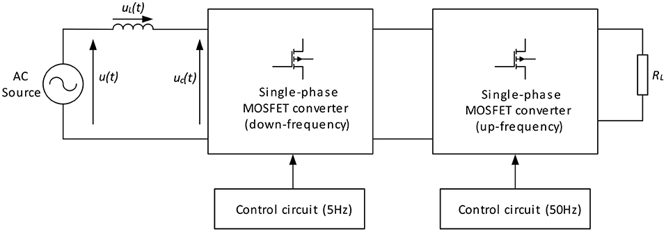
Figure 3. Block diagram of PWM ac-to-ac converters and associated elements.
The rectifier ac voltage is given in Equation (20).
where Δi(t) is the difference between the current given by the active line conditioning unit i*(t), the actual current i(t) measured at the rectifier's ac side, and hbw represents the hysteresis bandwidth.
After filtering the dc voltage of the rectifier, it is compared with the reference voltage . The error is subsequently applied to a PI voltage controller, which results in the active current, . The active current is computed on the basis of Equation (21).
where Kp and Ki are proportional and integral gains of the controller, respectively.
The active current is then applied to the line conditioning block. The block provides the appropriate signal i*(t) [depending on the conditioning signal c(t) and the measured ac voltage u(t)] corresponding to the required line conditioning mode. The function of this block is to decide which of the three mentioned operation modes it is necessary to implement based on the conditioning signal and all other inputs. The block outputs the reference current, and this is described in Equation (22).
where IMAX is the amplitude of the reference current of the rectifier, and is the active current's value given by the PI controller so that:
The signal i*(t) is compared with the actual current measured on the ac-side of the rectifier; i(t) and the result Δi(t) are applied to the bi-level current controller. The controller provides the control pulses for the rectifier's bridge (Paku and Marschalko, 2010).
Signal Analysis
When the proposed system is not bypassed by the consumer, the recommended 50-Hz power is supplied to the consumer appliances. However, when the consumer bypasses the metering part of the proposed system, the consumer appliance receives 5-Hz power. The single phase 5-Hz and 50-Hz rms voltages are depicted in Figures 4A,B, respectively.
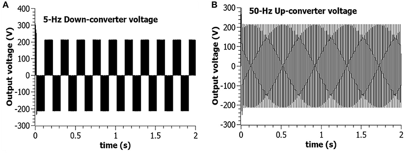
Figure 4. Single phase rms converter output voltage: (A) 5-Hz output voltage of down-converter; (B) 50-Hz output voltage of up-converter.
The effective value of an ac voltage (Veff) is given by Equation (24).
For a resistive load, the power supplied to the consumer's appliance under bypass condition is given by Equation (25).
where Vrms = RMS voltage; T = period of the signal; and v(t) = instantaneous value of voltage.
Equation (24) shows that if a consumer bypasses the proposed meter using a resistive load, the effective voltage across the load reduces as the frequency of the voltage is reduced to 5-Hz. By extension, Equation (25) shows that the power dissipated by the resistive load under bypass condition reduces in comparison with a 50-Hz supply.
If bypassed by a consumer using an inductive load, power losses caused by the load in the proposed system are expected to decline as a function of frequency (Hart, 2011), as provided by Equation (26). It is also intended to be capable of plug-and-play integration with a contemporary distribution system.
where,
XL = Line reactance in Ohms; f = nominal power frequency; L = Line inductance in Henry; Z = Line impedance in Ohms; R = Line resistance in Ohms; i = Line current in Amperes; and PLoss = Power loss in Watts.
Simulating the Proposed System
The system is first simulated in SimPowerSystems. Parameters of the distribution transformer, simulated distribution system, and converter are given in the Tables 1–4. The load is modeled as constant current type.
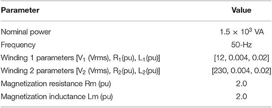
Table 1. Parameters of distribution transformer.
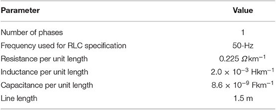
Table 2. Parameters of the simulated distribution line.
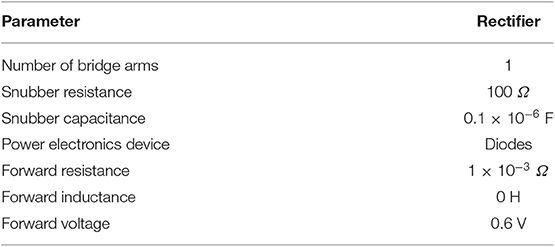
Table 3. Parameters of simulated rectifier for down-frequency converter.
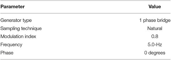
Table 4. Parameters of simulated pulse generator for down-frequency converter.
Experimental Setup and Test on the Proposed System
After the simulation, the proposed system is developed by realizing it using laboratory-scale power electronics components. The basic elements of the setup are shown in Figure 5 (photo of the setup excluding the supply mains and modified metering system). It consists of requisite measuring instruments and a modified distribution system with a modified energy metering system. Note that the modified metering system is not shown in Figure 5. The modified distribution system is interfaced with the modified metering system, which provides points for servicing a single-phase load.
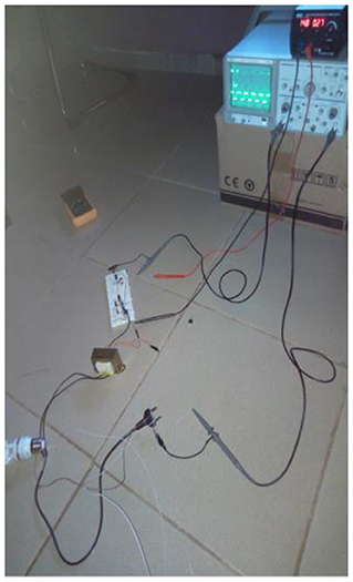
Figure 5. Photo showing part of the setup.
It is tested by first energizing it from the 50-Hz distribution system. Two categories of lamps are used as test appliances. One category is an incandescent type and the other is discharge type. Each lamp category is connected alternately first without bypassing the proposed system and subsequently with the proposed system bypassed, using a total of 10 lamps. Under both conditions, the response of each lamp is observed. In addition to lamps, the proposed system is tested using a hair clipper and phone chargers.
Results
Discussion of Simulated Response
Figures 4A,B depict rms values of the voltages at the outputs of down-frequency converters and up-frequency converters, respectively. As seen in Figure 4A, the voltage signal is unfiltered 5-Hz, while that of Figure 4B is a filtered 50-Hz signal. The 5-Hz signal is applied to the appliance of a consumer if he or she bypasses the proposed composite metering system (Figure 1B). The 5-Hz signal provides inadequate excitation of consumer appliances. Typically, when the 5-Hz signal is applied to the input of an appliance, which has a 50-Hz transformer at its input, the transformer presents reduced impedance but an increased winding current, reduction of flux linkages, and excessive winding loss (more heat). This results in inadequate operation of the appliance (Bimbhra, 1995).
In addition to inadequate excitation of consumer appliance, the unfiltered 5-Hz signal results in high noise and harmonics, as shown in Figure 6. Figure 6 presents Fast Fourier Transform (FFT) plots of the 5-Hz and 50-Hz voltage signals. The plot in Figure 6A indicates that the fundamental of the signal is centered at its nominal frequency but has a concentration of harmonics in both upper and lower frequencies. This is indicative of higher harmonic content in comparison with Figure 6B, which has minimal harmonics. The high harmonic content is additional suppressor of excitation when passed to inputs of consumer appliances, which lack adequate input filters (Mohan et al., 1995).
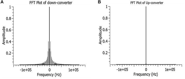
Figure 6. FFT plots of converter output voltage: (A) 5-Hz converter; (B) 50-Hz converter.
Response of Experimental Setup
The responses of the lamps when powered without bypassing the proposed system as well as when the proposed system is bypassed are observed and summarized in this section. All lamps in either category made consistent responses. The response of the discharge lamps was such that each lamp operated appropriately by glowing, without interruption or flickers, when the lamps were powered without bypassing the proposed system. However, when the lamps were powered by bypassing the proposed system, so that each lamp received its supply directly from the output of the down-frequency converter, each discharge lamp operated inappropriately with persistent flickers. The persistent flickers are unpleasant to human vision and present some degree of discomfort. It is expected that this is likely to demotivate consumers from bypassing the proposed metering system.
The incandescent lamps also responded with sustained glow when powered without bypassing the proposed system. However, when the same lamps were powered by bypassing the proposed system, their response resulted in a lack of glow, thus demotivating the bypassing of the proposed system for lighting by consumers.
Another household appliance used for testing was a hair clipper. When the clipper was supplied without bypassing the proposed system, the clipper responds adequately by properly cutting human hairs. However, when the clipper was supplied under bypass of the proposed system, the clipper responded with a humming noise and reduced cutting speed whilst also cutting human hair poorly and sometimes not cutting the hair at all, and this was occasioned by reduced supply frequency only.
Another household appliance used for testing was phone chargers. While some phone chargers operated, though with highly reduced charging speeds under bypass conditions, others did not operate to charge the phones under the same bypass condition.
Conclusion
This report presents an overview of the revenue loss by power distribution companies in sub-Saharan Africa using typical values of monthly revenue losses in Nigeria. It further presents a summary of attempts by researchers to solve the challenge of energy theft by residential consumers and drawbacks associated with proposed solutions. The major gap in literature is the fact that proposed solutions do not demotivate energy theft; instead, they detect when meter bypasses takes place. This leaves the power distribution companies to prosecute defaulting customers, and litigation becomes cumbersome since large number of residential consumers are involved, thus justifying the need for a system that demotivates energy theft. This paper presents a new approach to power distribution by adding a system that modifies the frequency of the power distribution such that, when the proposed metering and distribution system is bypassed, the consumer does not enjoy the energy, and this consequently demotivates energy theft by residential consumers. The proposed system is modeled and realized using power electronics components to represent a prototype 5-Hz distribution system. The system has been tested using lighting loads, and the response indicates flickers in the case of discharge lamps and non-response in the case of incandescent lamps. It is also developed to be capable of plug-and-play integration with a contemporary distribution system. An amount of 5-Hz was arbitrarily chosen to sufficiently reduce the frequency to ten times less than the nominal frequency of 50-Hz. The proposed system is not to detect energy theft but to mitigate and, subsequently, prevent energy theft. The link between the reduction of frequency and mitigation/prevention of energy theft is established: when the proposed system is further developed, prototyped, demonstrated outdoors, and deployed, word will go around that there is a new generation of energy meters that does not allow consumers who bypass the meter to enjoy an energy service. When consumers understand that it they are not rewarding to bypass the new meter, they will certainly be demotivated from energy theft through meter bypass. It is obvious that residential consumers bypass meters to enjoy the energy stolen, not to store the energy, resell the energy, or sabotage the service provider. Thus, when the consumer cannot enjoy theft of energy, energy theft by the consumer will be prevented, and revenue loss by the service provider will be mitigated. Finally, the work supports the established theory and contributes to scholarly efforts that seek to mitigate energy theft by residential consumers, improve the revenue collection of power distribution companies, and relieve the distribution networks of stress due to abusive consumer behavior.
Data Availability Statement
The raw data supporting the conclusions of this manuscript will be made available by the authors, without undue reservation, to any qualified researcher.
Author Contributions
The sole author designed, implemented and tested the project as well as the manuscript.
Funding
The author thanks Management and staff of Waziri Umaru Federal Polytechnic Birnin Kebbi for the support they provided in receiving the grant for this work from the Tertiary Education Trust Fund of Nigeria.
Conflict of Interest
The author declares that the research was conducted in the absence of any commercial or financial relationships that could be construed as a potential conflict of interest.
References
Adeniran, A. (2018). Mitigating Electricity Theft in Nigeria. Abuja: Centre for Public Policy Alternatives.
Akamihe, E., Omovbude, C., Fadipe, O., and Shekarau, A. (2018). Circular on Electricity Theft. Abuja: Abuja Electricity Distribution Company.
Aminu, M. A. (2016). Modeling and Simulation of Protective Relay for Short Circuits in AC Micro-Grids Using Fuzzy Logic. Perth, WA: Curtin University.
Antmann, P. (2009). Reducing Technical and Non-technical Losses in the Power Sector - Background Paper for the World Bank Group Energy Sector Strategy. Washington, DC: World Bank Group.
Collin, A. J., Tsagarakis, G., Kiprakis, A. E., and McLaughlin, S. (2014). Development of low-voltage load models for the residential load sector. IEEE Trans. Power Syst. 29, 2180–2188. doi: 10.1109/TPWRS.2014.2301949
Dike, D. O., Obiora, U. A., Nwokorie, E. C., and Dike, B. C. (2015). Minimizing household electricity theft in Nigeria using GSM based prepaid meter. Am. J. Eng. Res. 4, 59–69. doi: 10.6084/m9.figshare.1300012.v1
Dommel, H. (1969). Digital computer solution of electromagnetic transients in single and multiple networks. IEEE Trans. Power Apparatus Syst. 88, 388–399. doi: 10.1109/TPAS.1969.292459
Enwere, C., Aningo, G., and Okoye, C. (2016, September). Electricity sector operators raise alarm over meter bypass. Uyo: Vanguard Nigeria. Nigeria.
Garba, S., and Akpeneye, D. C. (2017). Order on Unauthorised Access, Meter Tampering and By-Pass. Abuja: The Nigerian Electricity Regulatory Commission.
Golden, M., and Min, B. (2011). “Theft and loss of electricity in an Indian State,” in IGC-ISI India Deleopment Policy Conference (Los Angeles, CA: University of California).
Mohan, N., Undeland, T. M., and Robbins, W. P. (1995). Power Electronics: Converters, Applications, and Design. New York, NY: John Wiley and Sons.
Oladejo, B. (2017, February). Eko electric laments energy theft and meter bypass. Sparkonline Newspaper. Nigeria.
Omijeh, B. O., Ighalo, G. I., and Anyasi, F. I. (2012). Intelligent power theft detection model for prepaid energy metering in Nigeria. Int. J. Electron. Commun. Comp. Eng. 3, 1366–1371.
Paku, R., and Marschalko, R. (2010). MATLAB/simulink/simpowersystems model for a PWM ac-to-dc converter with line conditioning capabilities. Acta Electrotechnica 51, 152–159.
Saikiran, B., and Hariharan, R. (2014). Review of methods of power theft in power system. Int. J. Sci. Eng. Res. 5, 276–280.
Seger, K. A., and Icove, D. J. (1988, March). Power Theft - The Silent Crime. Investigative Techniques - FBI Law Enforcement Bulletin, p. 20–25.
Tsagarakis, G., Collin, A. J., and Kiprakis, A. E. (2013). Statistical review of UK residential sector electrical loads. Int. J. Emerg. Electr. Power Syst. 14, 509–523. doi: 10.1515/ijeeps-2013-0078
Keywords: energy, power, loss, distribution, consumer
Citation: Aminu MA (2020) 5-Hz Distribution System for Mitigation of Energy Theft by Residential Consumers. Front. Energy Res. 7:153. doi: 10.3389/fenrg.2019.00153
Received: 16 September 2019; Accepted: 06 December 2019;
Published: 14 January 2020.
Edited by:
Chau Yuen, Singapore University of Technology and Design, SingaporeReviewed by:
Wen-Tai Li, Singapore University of Technology and Design, SingaporeHwei-Ming Chung, University of Oslo, Norway
Copyright © 2020 Aminu. This is an open-access article distributed under the terms of the Creative Commons Attribution License (CC BY). The use, distribution or reproduction in other forums is permitted, provided the original author(s) and the copyright owner(s) are credited and that the original publication in this journal is cited, in accordance with accepted academic practice. No use, distribution or reproduction is permitted which does not comply with these terms.
*Correspondence: Maruf A. Aminu, bWFydWYuYW1pbnVAZ21haWwuY29t