 A. Elnady
 M. Al-Shabi
 Ali Ahmed Adam1
- 1Electrical and Computer Engineering Department, University of Sharjah, Sharjah, United Arab Emirates
- 2Royal Military College, Electrical and Computer Engineering Department (adjunct), Station Forces Kingston, Kingston, ON, Canada
- 3Mechanical and Nuclear Engineering Department, University of Sharjah, Sharjah, United Arab Emirates
This paper introduces a new operational scheme for several multilevel (five-level diode-clamped) inverters in the microgrid. The presented operational scheme has a central structure (different from the distributed controllers for droop schemes) to alleviate the drawback of the conventional droop control for microgrid operation. The contribution of this paper is focused on the suggested operational scheme, which has two contributory components. The first component is the novel smooth variable structure filters (SVSF), which are formulated to estimate the disturbances of voltage harmonics and voltage unbalance. The second component is an efficient adaptive sliding mode controller to operate these inverters. This proposed operational achieves equal power sharing among working inverters, compensating for voltage unbalance at the point of common coupling (PCC) at loads, and mitigation for voltage harmonics at the PCC. More importantly, the propounded operational scheme efficiently stabilizes voltage with the variation of balanced, unbalanced, and non-linear loads in addition to the seamless transient and steady-state performance for injected power by inverters. The performance of the suggested operational scheme is justified by simulation results.
Introduction
The microgrid has become into the focus of research at the distribution system level because microgrid fetches some merits such as low-carbon emission, its modularity, integration of renewable dispersed energy sources, and its ability to work independently or connected to the central power grid (Jiayi et al., 2008; Mariam et al., 2013). In addition to aforementioned merits, any microgrid has also several challenges such as the stability of voltage and frequency with variable loads, existence of harmonics due to non-linear loads, control of dispersed energy sources, circulating current among inverters, existence of inverters associated with renewable energy sources, and procedure for connection/disconnection to/from the central grid (Parhizi et al., 2015; Hirsch et al., 2018).
The operational scheme for the microgrid becomes a challenging research topic because it is supposed for this scheme to realize several simultaneous objectives. Therefore, some publications survey/review the types/structures of operational/control schemes employed to operate the microgrid (Huang et al., 2011; Vandoorn et al., 2013; Canizares and Palma-Behnke, 2014; Han et al., 2016a; Rajesh et al., 2017; Sen and Kumar, 2018). The idea presented in this paper focuses on how the voltage harmonics and voltage unbalance are mitigated in addition to stabilizing the voltage at the loads' side with different loading conditions for linear and non-linear loads. Therefore, the coming literature survey explicates the state-of-art for the mitigation and extraction tools for harmonics and voltage unbalance within microgrid environments.
The conventional droop control has two levels (primary and secondary), and the voltage unbalance is compensated at the secondary level by the control action of the proportional integral (PI) controller (Lexuan et al., 2015). This presented droop control in Lexuan et al. (2015) is used to equalize the power among three two-level inverters, and there are no details on how the negative-sequence is extracted. Another enhanced control scheme is designed for a four-leg inverter (Moghaddam et al., 2018). This inverter is powered by a battery based energy storage system under unbalanced and non-linear loads. The operational scheme of this inverter is operated using the decoupled model in the d − q frame such that the total harmonic distortion (THD) and unbalance factors are reduced. A hierarchical droop control of Savaghebi et al. (2012) includes the primary and secondary control levels. Its primary control has a local droop control for active and reactive power. Meanwhile, the central secondary controller is designed to manage the compensation of voltage unbalance at the PCC in the microgrid. An operational scheme including double control loops for the positive and negative-sequence currents in the d − q frame is developed to mitigate the current unbalance (Reyes et al., 2012). This presented control scheme is further improved by adding a filter to get rid of double the fundamental frequency in this frame. The droop control scheme presented in Ren et al. (2018) is integrated with voltage unbalance compensation, but this paper does not give details of how voltage unbalance is extracted and mitigated. Another multi-function operational scheme, which handles voltage unbalance compensation, harmonic power sharing, selective virtual harmonic impedance, virtual fundamental impedance, and conventional droop control is introduced in Han et al. (2016b). Its secondary loop is employed to restore the voltage and frequency to their normal values with help of proportional resonant (PR) controllers. Meanwhile, its primary control loop operates the inverters such that the power is equally divided among the working inverters. A virtual impedance loop inside the droop control scheme is modified to include the voltage unbalance and harmonics compensation (Liu et al., 2014), in which the harmonic voltage drop and unbalanced voltage drop are mitigated by the control action of PR and PI controllers. New cascaded loops of voltage and current for the positive and negative-sequence voltages are proposed in Acharya et al. (2019), and the extraction of the negative-sequence voltage and current is done using passive filters in the d − q frame. The proposed scheme of Acharya et al. (2019) achieves a reduction of the negative unbalance factor to be smaller than 2%. The conventional droop control along with two traditional levels (primary and secondary) is suggested in Savaghebi et al. (2011, 2013), at which the secondary control level of the droop scheme is used to calculate the power of negative-sequence components (voltage and current) and converted into a reference voltage. This reference voltage is summed with other references to operate the primary control level. Another cascaded structure of voltage and current control loops for each working inverter is introduced in Zhao et al. (2015), where the virtual impedance loop contributes to the voltage references, and these references are applied to the voltage loop. The extraction of the negative-sequence voltage in Zhao et al. (2015) is conducted in the d − q frame using a passive filter. Thus, this extracted negative-sequence voltage is converted into a voltage reference that is augmented with other voltage references. Another technique for compensating voltage unbalance is realized by the extraction and mitigation of the negative-sequence current (Shi et al., 2016), which is extracted and converted into a current reference that is applied to the current loop of the primary control level in its droop scheme.
This paper introduces a new technique for the extraction of voltage disturbances (particularly voltage unbalance and harmonics). The forthcoming paragraph gives a brief survey about the different extraction/estimation tools that have been developed to estimate those voltage disturbances. The most common technique to extract the voltage unbalance is to convert the phase voltages from the a-b-c natural frame to the d − q frame, and then a low-pass filter is used to distinguish between the positive and negative-sequence voltages (Reyes et al., 2012; Moghaddam et al., 2018; Acharya et al., 2019). The estimation of voltage unbalance is also reported in Javier Alcántara and Salmerón (2005) by three blocks of the neural network: The 1st block is to estimate the Parks vector and the zero-sequence voltage, while the 2nd block is employed to estimate the harmonics, and the 3rd block is dedicated to estimate the voltage unbalance components. The adaptive linear neuron (ADALINE) is used to estimate the negative- and positive-sequence components, it works well, but its formulation is based on matrix equations, which consume much time for its calculation (Marei et al., 2004). The extended Kalman filter is developed to estimate the positive and negatives-sequence voltage in the α − β frame (Sun and Sahinoglu, 2011), and the extended part of Kalman filter is used to detect any variation in the fundamental frequency. The linear Kalman filter is adopted to estimate the positive and negative-sequence voltage (Soliman and El-hawary, 1997), in which the developed model presents the state transitional matrix in the form of an identity matrix, and the measurements matrix varies with time. The presented results in Soliman and El-hawary (1997) show an accurate estimation, but the existence of harmonics is not included.
Most of aforementioned publications (Savaghebi et al., 2011, 2012, 2013; Reyes et al., 2012; Liu et al., 2014; Lexuan et al., 2015; Zhao et al., 2015; Han et al., 2016b; Shi et al., 2016; Moghaddam et al., 2018; Ren et al., 2018; Acharya et al., 2019), are related to the extraction and mitigation of voltage disturbances in the microgrid, and some of these publications suffer some flaws such as,
• The mitigation of the voltage unbalance is done through the droop control scheme at the secondary control level, which adds more complexity to the employed droop operational scheme.
• The voltage unbalance is calculated in the α − β frame or d − q frame using the PLL and passive filters, which lead to error in the magnitude of extracted unbalance components.
• The mitigation of voltage unbalance is done through the negative-sequence voltage only; meanwhile, the connection of the microgrid to the ground is common (Mohammadi et al., 2019), which yields zero-sequence components in the microgrid. In the most of publications (Savaghebi et al., 2011, 2012, 2013; Reyes et al., 2012; Liu et al., 2014; Lexuan et al., 2015; Zhao et al., 2015; Han et al., 2016b; Shi et al., 2016; Moghaddam et al., 2018; Ren et al., 2018; Acharya et al., 2019), the zero-sequence voltage is not considered for mitigation in the microgrid.
The contribution of this paper is exemplified in the development of an operational scheme, which is designed in such a way to alleviate the preceding drawbacks in addition to stabilizing the voltage at any variation in loading conditions of the microgrid. The operational scheme has two main contributory points: Estimation of voltage disturbances and controlling of multilevel inverters. The paper is organized in five main sections. The second section demonstrates the microgrid under study. The third section shows the operational scheme along with the formulation of the smooth variable structure filter to estimate the current harmonics and voltage unbalance. The fourth section illustrates simulation results. The last section summarizes the findings of the paper.
Microgrid Under Study
The microgrid under study, shown in Figure 1, has three dispersed energy sources, which are PV solar arrays connected to battery systems. Their harvested energies are injected to the microgrid through three inverters; each three-phase inverter consists of three single-phase full-bridge five-level diode-clamped inverters whose topology and its output voltage waveforms are already given in Figures 2A,B, respectively.
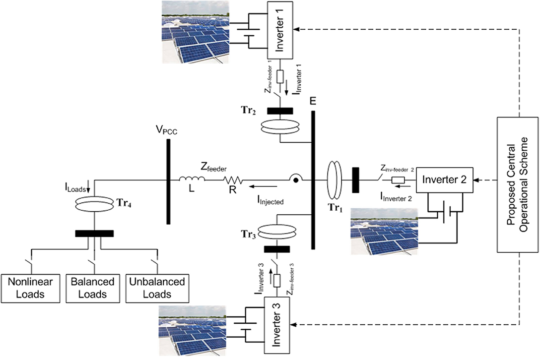
Figure 1. Microgrid under study.
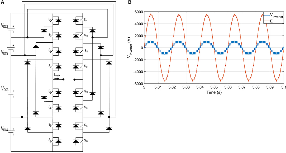
Figure 2. Topology of utilized multilevel inverter with its injected voltage. (A) Topology five-level diode-clamped inverter per phase. (B) Voltage waveforms before and after transformer Tr1 for one phase of inverter 2.
In this research, all inverters are have the same topology as shown in Figure 2A and have the same rating as written in Table 1. The loads in the microgrid are groups of balanced, unbalanced, and non-linear loads. The parameters of the microgrid are given in Table 1.
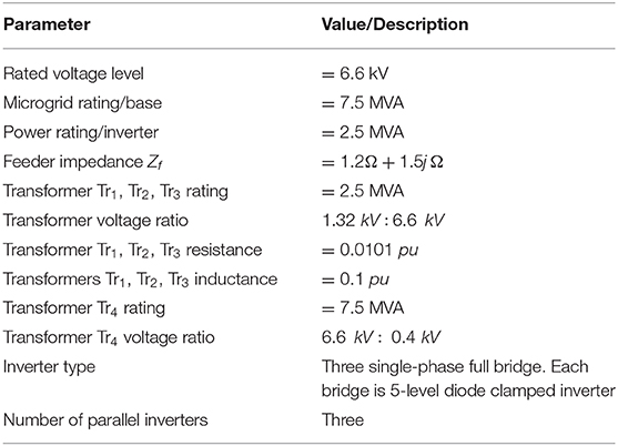
Table 1. Microgrid and inverter parameters.
Each inverter circuit is operated by the phase-disposition pulse width modulation (PD-PWM), where the control signal is compared to four carrier signals with 3-kHz to operate the first leg for switches from S1 to S8 in Figure 2A and the inverted control signal is used to operate the other leg of switches from S9 to S16 in Figure 2A. The details of its operation are documented in Elnady and Suleiman (2017).
Proposed Operational Scheme
The contribution of this paper includes two mains components, which are the development of the novel SVSF for the estimation of voltage harmonics/unbalance and the employment of adaptive sliding mode controller to operate the inverters. This section is divided into three different subsections. The first subsection is related to the development of the SVSF to estimate the disturbances, the second subsection shows the formulation of the adaptive sliding mode controller, and the last subsection illustrates the structure of the whole operational/control scheme of the microgrid.
Smooth Variable Structure Filter
The Smooth Variable Structure Filter (SVSF) is a new estimation filter that was recently developed and evolved through several works such as Al-Shabi et al. (2013), Gadsden et al. (2015), and Al-Shabi and Elnady (2019). The basic idea is that the SVSF uses a switching hyperplane from the measurement and forces the estimate to be in its neighborhood. This filter will be newly formulated in this work to estimate the voltage harmonics and unbalance in the microgrid of Figure 1. The mechanism of operation for the SVSF is simple, it can be summarized as,
Firstly: an unrefined estimate is obtained as follows:
where,
Xunrefined,k is the in-phase of the voltage harmonics and is defined as,
A and H are the voltage harmonics in the microgrid and measurement matrices are they are defined as,
Ts is the sampling time, and zunrefined,k is the total voltage harmonics and are defined as,
This step is similar to the one used in Kalman filter presented in Girgis et al. (1991).
Secondly, the estimate is refined to its final refined value as follow:
where
and ψ is the boundary layer to be tuned to obtain the best results. For simplicity, γ is assumed to have a value of zero. This proposed filter is simpler than the Kalman filter in three main points
• The formulation using Kalman filter depends on calculating the covariance matrix and updating it continuously. Then, this updated covariance matrix is used to calculate the corrective gain, which is the refined estimate.
• The noise covariance matrices of Kalman filter (Q and R) are not easy to be tuned (Girgis et al., 1991). No information can be obtained for the microgrid noise. Moreover, this noise cannot be assumed as white noise as in Kalman filter, as it includes of voltage and current harmonics.
• Formulation of this proposed filter [as given in (1) and (6–8)] is also easier than the perdition-correction formulation of Kalman filter (Girgis et al., 1991).
After the fundamental voltage and voltage harmonics are estimated using the formulation given in (1–8). This estimated fundamental voltage contains the unbalance components. The same procedure was used to extract the unbalanced voltages. Its formulation is similar to the previous formulation such that the state-space form in (9) for positive and negative-sequence voltages replaces (2), and it is written as,
also replacing (3) and (4) with
and finally replacing zk with
The refined estimates are given as follow:
where Wi, k is the ith row of the matrix/vector W at time step k. The positive and negative-sequence voltages are then obtained in (14) as,
Finally, the previous formulation estimates the voltage harmonics and voltage unbalance in two different stages. The 1st stage [formulation from (1) to (8)] is used to estimate the fundamental voltage and harmonics, while the 2nd stage [formulation (1), (6–8), (9–14)] receives the fundamental voltage from the 1st stage and it produces the voltage unbalance components (positive, negative, and zero-sequence voltages). All these estimated voltage disturbances/components are used in the operational scheme as will explained later.
Adaptive Sliding Mode Control
The adaptive sliding mode control adopted in this paper comprises of two inputs to form its control law. The suggested control law is based on the state-space model of the microgrid depicted in Figure 1, this state-space model is deduced and given for the positive sequence components in the d-q rotating frame as,
where E is the injected voltage of the inverters, VPCC is the voltage at the loads' side. R and L are the equivalent resistance and inductance of the main feeders inside the microgrid between E bus and VPCC bus. Iloads is the equivalent current of loads. The previous equations can be rewritten in a state space form as,
Equations (15) and (16) are general and can be used for the positive-sequence and negative-sequence components as well with changing the sign of ω. The suggested control law is expressed as,
Each term in (17) represents the required input (injected) voltage by each inverter to the system in order to realize the objective of the control scheme. The udis is the discrete input that transfers the system's states from a certain sliding manifold (surface) to another, while ueq is the equivalent input that keeps the system's states on a certain sliding manifold. This sliding manifold is innovatively defined by an integral form as,
where n is the number of states, λ1 and λ2 are positive constants, and e is the error which is defined as,
The ueq is designed such that the system with the sliding mode controller becomes stable, the system stability is justified by Lyapunov stability criterion such that a certain Lyapunov function is selected to express the distance between the system's state and sliding manifold, its definition is written as,
The derivative of this function should be less than or equal to zero as,
For tracking the state variables like the case of this paper , which leads to
Finally, the equivalent input of the control law ueq is given by,
The matrices (A, B, F) of (23) are obtained from their definition in (16) for positive and negative-sequence components based on the system's parameters of Table 1. The discrete input of the control law udis is deducted from Huang et al. (2008) and defined by its adaptive form for the positive and negative-sequence components as,
Eventually, the suggested sliding surface in (18) and its control law in (17) along with its two terms in (23) and (24) are employed to control the inverters in such a way to inject a certain voltage, which is used to realize all objectives of the suggested operational/control scheme.
Structure of Operational Scheme
The previous two subsections attribute the contribution of this paper along with the suggested structure of the operational scheme, which is given in Figure 3. The operational scheme has two contributory components, which are the estimation for disturbances using SVSF and the adaptive SMC based control scheme to operate the inverters.
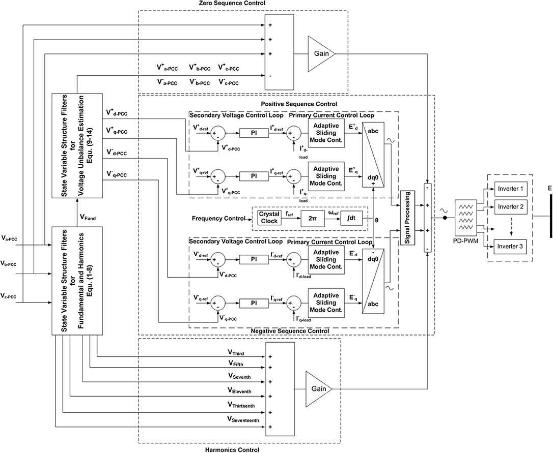
Figure 3. Suggested operational (control) scheme for microgrid.
The objective of the estimation tool, SVSF, along with the developed state-space models is to estimate/extract voltage harmonics (1–8) and voltage unbalance (9–14), which are used to get the feedback voltages in the operational scheme of Figure 3. The positive-sequence voltage represents the dominant voltage in the microgrid, while the negative-sequence voltage represents the most common disturbance in the microgrid. Therefore, these two loops are controlled using cascaded structure of voltage and current control loops. The voltage control loop receives the required voltages (set values) based on the values given in Table 1, and it produces current references to the current control loop. The current control loop is the corner stone in this control scheme because it deals with non-linear systems (inverters along with switching modulation and the grid). Thus, its controller should provide adaptive and fast characteristics toward any change in loads. The adopted controller in the voltage loop is the PI controller and the utilized controller in the current loop is the adaptive SMC. Both harmonics mitigation and unbalance compensation are realized after the extraction of their disturbances using the two estimation blocks depicted in Figure 3, and then these disturbances are processed to generate corresponding control signals. Consequently, these control signal are augmented to operate the PD-PWM and inject particular voltages as illustrated in Figure 3. Finally, these voltages are employed to cancel voltage unbalance and harmonics at the PCC. The frequency of the generated voltage by inverters in the microgrid is constant because the frequency of the control signal, used to drive the PD-PWM and generate the injected voltage, is obtained from a constant crystal clock (fixed frequency source) as depicted in Figure 3. More importantly, the frequency of this control signal within the switching modulation (PD-PWM) does not change with any load changes. Thus, the frequency of the injected voltage does not change with any load change accordingly. This point is considered as a great advantage compared to the conventional droop control schemes, at which both the frequency and magnitude of the injected voltage change with any variation in loads (Huang et al., 2011; Canizares and Palma-Behnke, 2014; Sen and Kumar, 2018). These voltage changes should be corrected at the secondary control level within the droop schemes. This voltage correction adds more complexity to the employed control scheme.
Simulation Results
This section is divided into several subsections. The first subsection illustrates the performance of the SVSF for estimation of the voltage harmonics and unbalance. The second subsection displays the performance of the presented controller. The last section shows the performance of the whole operational scheme. All results of coming subsections are obtained when the microgrid has several loads (referred to primary side of Tr4), changing as follows:
• From t = 0 to t = 2 s, the 1st balanced three-phase load of Zload1 = 55 + 18.84j and 2nd balanced three-phase load of Zload2 = 65 + 31.4j are connected in parallel in the microgrid.
• From t = 2 s to t = 4 s, the 2nd load Zload1is disconnected.
• From t = 4 to t = 6 s, the 1st unbalanced three-phase load is connected to the microgrid with the values of Z1 − ph − a = 25 + 6.28j, Z1 − ph − b = 50 + 31.4j, Z1 − ph − c = 35 + 15.7j.
• From t = 6 s to t = 8 s, the 2nd unbalanced three-phase load is connected to the microgrid with the values of Z2 − ph − a = 30 + 9.42j, Z2 − ph − b = 33 + 11j, Z2 − ph − c = 45 + 14.13j.
• From t = 8 s to t = 10 s, a non-linear load of full rectifier circuit with an inductive load is connected to the microgrid with R = 100 Ω, H = 50 mH.
Performance of SVSF
The formulation of the SVSF along with the harmonics state-space equations presented before is used to estimate the fundamental voltage and voltage harmonics (1st stage estimation); then, the estimated three-phase fundamental voltages are applied on another SVSF to estimate the positive, negative, and zero-sequence voltages (2nd stage estimation). The instantaneous estimation performance of the 1st stage SVSF for the fundamental and some voltage harmonics is given in Figures 4A,B for fundamental voltage and voltage harmonics, respectively. The instantaneous estimated fundamental voltage is displayed with the actual distorted voltage at the PCC for one phase. The voltage harmonics in Figure 4B are estimated using the SVSF with the state-space formulation presented in section Smooth variable structure filter. The performance of the 2nd stage SVSF is depicted in Figure 5, where it shows the instantaneous estimation of the voltage unbalance components for the 2nd unbalanced loads.
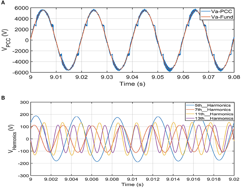
Figure 4. Performance of 1st stage SVSF for fundamental and harmonics voltage at PCC. (A) Estimated fundamental voltage with actual voltage. (B) Estimated voltage harmonics.
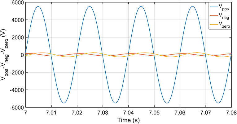
Figure 5. Performance of 2nd stage SVSF for voltage unbalance components at PCC.
Performance of Adaptive Sliding Mode Controller
The performance of control scheme is displayed in this subsection. The development of the adopted controller is described in section Adaptive sliding mode control. The controller parameters for both loops are given in Table 2. This presented controller is compared with regular PI controllers to prove its meritorious performance. Simply, these PI controllers are replaced the adaptive SMC in the scheme of Figure 3. The parameters of the PI controllers for their best performance are tuned by the empirical modified Ziegler-Nichols method, and they are listed in Table 3.
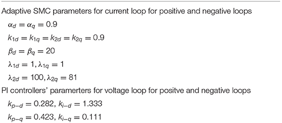
Table 2. Parameters of adaptive SMC.
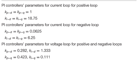
Table 3. Parameters of PI controllers.
The performance of the adaptive SMC is depicted in Figure 6A, where it shows its performance with that of the regular PI controllers whose parameters are tuned using Ziegler-Nichols method. The good performance of the voltage stability at the PCC emanates from the control action in the current loops. The current reference and its feedback for the direct axis current control (just as an example) are depicted in Figure 6B.
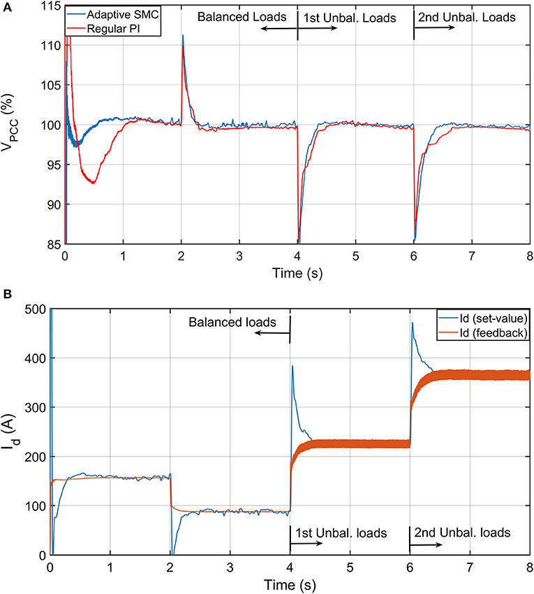
Figure 6. Performance of proposed operational (control) scheme for voltage stability at PCC. (A) Performance of adaptive SMC vs. PI controllers for voltage stability. (B) Performance of currents in current control loop of d-axis.
Performance of Operational Scheme
The suggested operational scheme belongs to the central control category and its output is applied to all inverters at the same time (Huang et al., 2011; Canizares and Palma-Behnke, 2014; Rajesh et al., 2017; Sen and Kumar, 2018). This concept brings some important advantages which are
• The power/current is equally divided among working inverters.
• The difference in feeder impedance does not badly influence its operation.
• Its simplicity compared to the droop scheme presented in Huang et al. (2011), Vandoorn et al. (2013), Canizares and Palma-Behnke (2014), Han et al. (2016a), and Sen and Kumar (2018).
Power Sharing Among Inverters in Microgrid
One major advantage of this control scheme is its central structure. Meaning, the output control signals are applied on all inverters at the same time, which yields equal power sharing among the working inverters. Even if one inverter is lost for any reason, the other working inverters share the whole load power. The power of each inverter vs. the total load power is given in Figure 7, which shows equal power (active and reactive) for all three inverters. In Figure 7B, the reactive power of each inverter is close to the reactive power of other inverters; consequently, they look above each other.
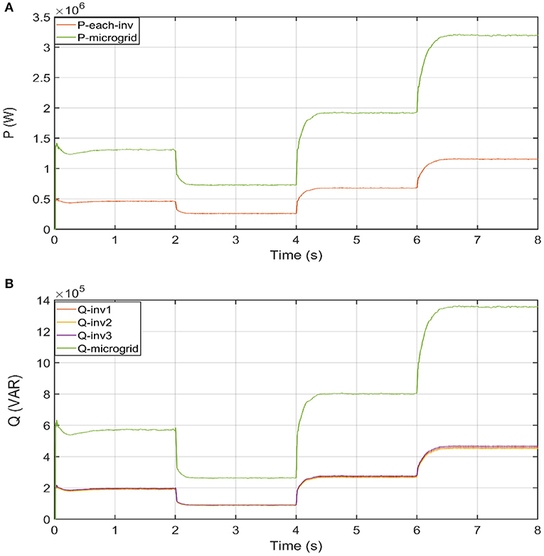
Figure 7. Power sharing among three inverters. (A) Active power sharing. (B) Reactive power sharing.
Voltage Unbalance Mitigation in Microgrid
The mitigation of the voltage unbalance starts with the extraction of the unbalance components (positive, negative, and zero-sequence voltages), this extraction process is conducted continuously through the state variable structure filters block for voltage unbalance in Figure 3. The output of this block is minimal and neglected in case the loads are balanced. If the loads are unbalanced, then the unbalance components are considerable, and these components are extracted, processed, and mitigated as will be illustrated in Figures 8, 9. The three-phase unbalanced voltages are shown in Figure 8A. Their estimated voltage unbalance components are already given in Figure 5. These voltages are processed by the scheme of Figure 3 to generate a voltage reference. The three-phase voltages with the mitigation of the negative-sequence and zero-sequence components are apparent in Figure 8B. The efficiency of the mitigation for voltage unbalance is justified by the negative and zero unbalance factor (defined in IEEE Std. 1159–1995) as,
The efficiency of the voltage waveforms given in Figure 8 is affirmed by the negative- and zero-unbalance factor without and with the activation of the negative-voltage control loop and zero-voltage loop. These negative- and zero-unbalance factors are shown in Figures 9A,B, respectively. With the activation of the unbalance loop, the negative- and zero-unbalance factors (UVF−, UVF0) are less 2% as stipulated in IEEE Std. 1159–1995.
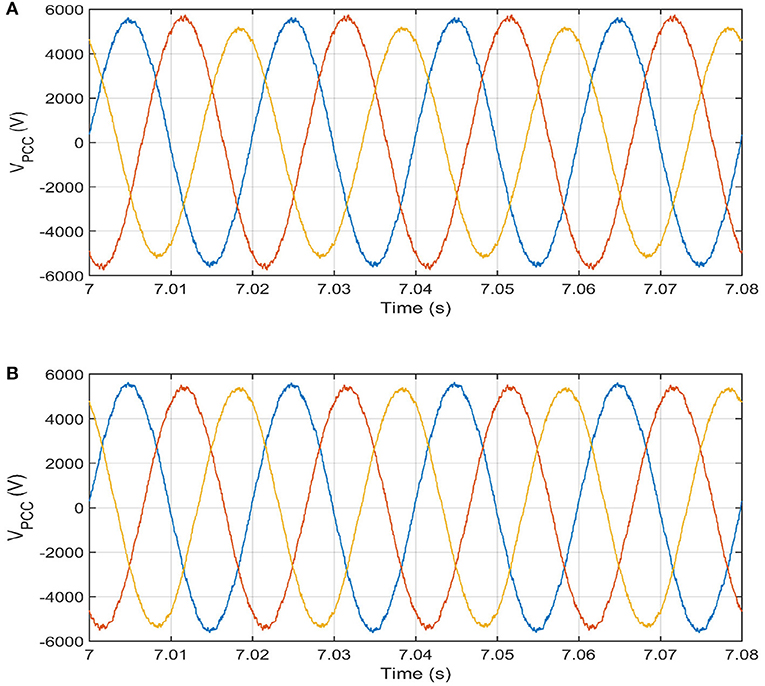
Figure 8. Voltage waveforms before and after the activation for mitigation of voltage unbalance at 2nd unbalanced load (from t = 6 s to t = 8 s). (A) Voltage waveforms at PCC for 2nd unbalanced loads without mitigation. (B) Voltage waveforms at PCC for 2nd unbalanced loads with mitigation.
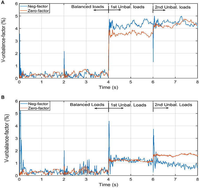
Figure 9. Voltage unbalance factors before and after the activation of unbalance control. (A) Voltage unbalance factor without activation of unbalance control. (B) Voltage unbalance factor with activation of unbalance control.
Voltage Harmonics Mitigation in Microgrid
Starting from t = 8 s, the non-linear load is connected to the microgrid, which injects current harmonics such as 3rd, 5th, 7th, 11th, 13th, … etc. In this research, these harmonics are estimated through the formulation given in section Smooth variable structure filter. The three-phase voltages at the PCC without and with the activation of the harmonics loop is depicted in Figures 10A,B, respectively. The efficiency of harmonics mitigation is affirmed by the total harmonic distortion and harmonic spectrum. The harmonic spectrum without and with the activation of the harmonic mitigation loop is illustrated in Figures 11A,B, respectively. The harmonic spectrum reflects the THD at the PCC, which is transferred from 9 to 3%.
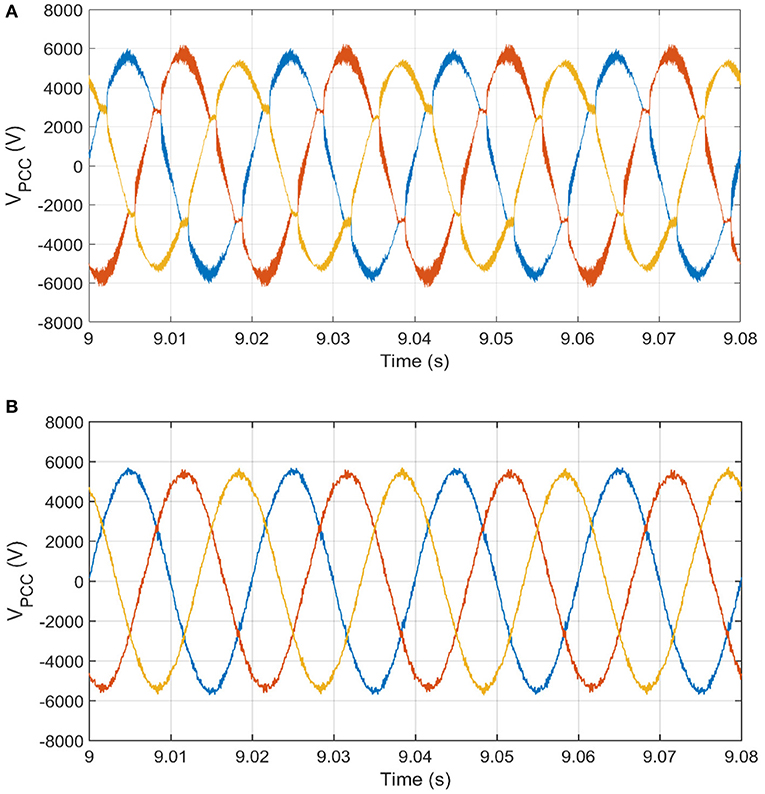
Figure 10. Voltage waveforms at PCC before and after the activation of unbalance and harmonics control. (A) Voltage waveform at PCC distorted by harmonics and unbalance. (B) Voltage waveform at PCC with mitigation of harmonics and unbalance.
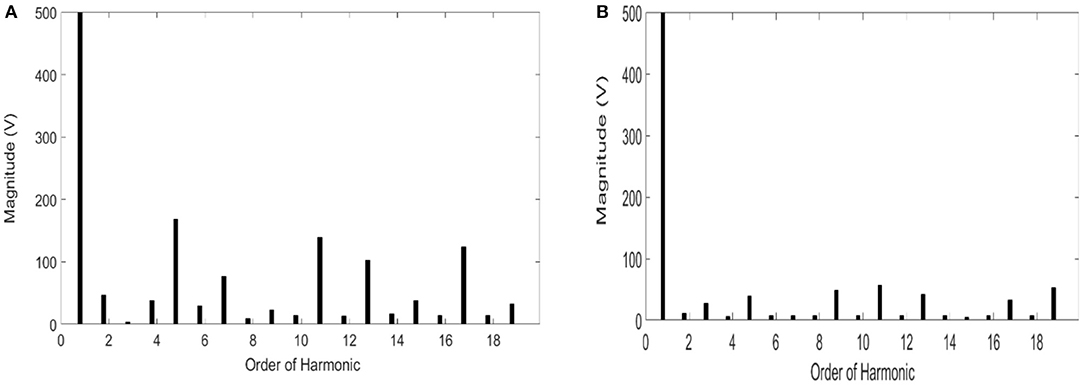
Figure 11. Harmonic spectrum before and after the activation of harmonics control. (A) Harmonic spectrum before activation of harmonics loop. (B) Harmonic spectrum after activation of harmonics loop.
The good performance for stabilizing the voltage and power sharing at loads side is verified by the preceding simulation results. For the real time implementation, it is expected to have a slight difference in results for equal power sharing because identical inverters along with their operation cannot be practically guaranteed, which may lead to unequal power generation among the inverters and a small circulating current due to a small difference in the generated voltage by each inverter.
Conclusion
This paper presents an effective operational/control scheme, which is able to achieve some objectives in the microgrid. These multiple objectives of the operational scheme have been realized because the proposed scheme has two main contributory components. The 1st component is the newly developed SVSF, which is used to estimate all voltage disturbances under study in this paper. The 2nd component is the adaptive SMC along with its integral sliding surface, which gives a seamless transient and steady-space performance for the injected voltage/power of inverters. The integration of the SVSF and adaptive SMC enables the operational scheme to give the optimum required voltage/power performance at the loads. The voltage is stabilized at the PCC to 1 pu for any loading condition. In addition, the unbalance factors (negative and zero-sequence voltages) at the PCC become <2%, and voltage harmonics (3rd, 5th, 7th, 11th, 13th, 17th) at the PCC are smaller than 5%. More importantly, the loads' power is equally shared among the working inverters.
Data Availability Statement
All datasets generated for this study are included in the article/Supplementary Material.
Author Contributions
AE has contributed to everything in the paper including idea under study in the paper, the modeling of the system under study, mathematical equation development, simulation results, analysis of the results, and finally editing and proofreading the whole paper. MA-S has contributed to modeling of the system under study, mathematical equation development, simulation results, analysis of the results, and finally editing the whole paper. AA has contributed to modeling of the system under study, mathematical equation development, reviewing the whole paper, and editing and proofreading.
Funding
This research work is sponsored by the University of Sharjah under the grant no 1802040393-P and 1602040826-P.
Conflict of Interest
The authors declare that the research was conducted in the absence of any commercial or financial relationships that could be construed as a potential conflict of interest.
References
Acharya, S., El-Moursi, M. S., Al-Hinai, A., Al-Sumaiti, A. S., and Zeineldin, H. (2019). A control strategy for voltage unbalance mitigation in an islanded microgrid considering demand side management capability. IEEE Trans. Smart Grid 10, 2558–2568. doi: 10.1109/TSG.2018.2804954
Al-Shabi, M., and Elnady, A. (2019). Recursive smooth variable structure filter for estimation processes in direct power control scheme under balanced and unbalanced power grid. IEEE Syst. J. 1–12. doi: 10.1109/JSYST.2019.2919792
Al-Shabi, M., Gadsden, S., and Habibi, S. (2013). Kalman filtering strategies utilizing the chattering effects of the smooth variable structure filter. J. Signal Proce. 93, 420–431. doi: 10.1016/j.sigpro.2012.07.036
Canizares, C. A., and Palma-Behnke, R. (2014). Trends in microgrids control. IEEE Trans. Smart Grid 5, 1905–1919. doi: 10.1109/TSG.2013.2295514
Elnady, A., and Suleiman, M. S. (2017). Simulation and experimental comparison between multilevel and conventional inverters. Int. J. Power Energy Syst. 37, 1–10. doi: 10.2316/Journal.203.2017.3.203-6329
Gadsden, S. A., Al-Shabi, M., and Kirubarajan, T. (2015). Square-root formulation of the SVSF with applications to nonlinear target tracking problems. J. Signal Process 9474, 1–12. doi: 10.1117/12.2177226
Girgis, A., Chang, W., and Makram, E. (1991). A digital recursive measurement scheme for on-line tracking of power system harmonics. IEEE Trans. on Power Deliv. 6, 1153–1991. doi: 10.1109/61.85861
Han, H., Hou, X., Yang, J., Wu, J., Su, M., Guerrero, J., et al. (2016a). Review of power sharing control strategies for islanding operation of AC microgrids. IEEE Trans. Smart Grid. 7, 200–215. doi: 10.1109/TSG.2015.2434849
Han, Y., Chen, P., Zhao, Z., and Geurrero, G. M. (2016b). An enhanced power sharing scheme for voltage unbalance and harmonics compensation in an AC islanded microgrid. IEEE Trans. Energy Convers. 31, 1037–1050. doi: 10.1109/TEC.2016.2552497
Hirsch, A., Parag, Y., and Guerrero, J. (2018). Microgrids: a review of technologies, key drivers, and outstanding issues. J. Renew. Sustain. Energy Rev. 90, 402–411. doi: 10.1016/j.rser.2018.03.040
Huang, W., Lua, M., and Zhang, L. (2011). Survey on microgrid control strategies. J. Energy Proc. 12, 206–212. doi: 10.1016/j.egypro.2011.10.029
Huang, Y. J., Kuo, T. C., and Chang, S. H. (2008). Adaptive sliding-mode control for nonlinear systems with uncertain parameters. IEEE Trans. Syst. Man Cy-s Part B 38, 534–544. doi: 10.1109/TSMCB.2007.910740
Javier Alcántara, F., and Salmerón, P. (2005). A new technique for unbalance current and voltage estimation with neural networks. IEEE Trans. Power Syst. 20, 852–858. doi: 10.1109/TPWRS.2005.846051
Jiayi, H., Chuanwen, J., and Rong, X. (2008). A review on distributed energy resources and microgrid. J. Renew. Sustain. Energy Rev. 12, 2472–2483. doi: 10.1016/j.rser.2007.06.004
Lexuan, M., Xin, Z., Fen, T., Mehdi, S., Tomislav, D., Vasquez, Q., et al. (2015). Distributed voltage unbalance compensation in islanded microgrid by using dynamic consensus algorithms. IEEE Trans. Power Electr. 31, 827–838. doi: 10.1109/TPEL.2015.2408367
Liu, Q., Tao, Y., Liu, X., Deng, Y., and He, X. (2014). Voltage unbalance and harmonics compensation for islanded microgrid inverters. IET Proc. Power Electr. 7, 1055–1063. doi: 10.1049/iet-pel.2013.0410
Marei, M. I., El-Saadany, E. F., and Salama, M. M. A. (2004). A processing unit for symmetrical components and harmonics estimation based on a new adaptive linear combiner structure. IEEE Trans. Power Deliv. 19, 1245–1252. doi: 10.1109/TPWRD.2004.829110
Mariam, L., Basu, M., and Conlon, M. F. (2013). A review of existing microgrid architectures. J. Eng. 2013:937614. doi: 10.1155/2013/937614
Moghaddam, M., Kalam, A., Miveh, M., Naderipour, A., Gandoman, F. H., Reza Miveh, M., et al. (2018). Improved voltage unbalance and harmonics compensation control strategy for an isolated microgrid. Energies 11, 1–26. doi: 10.3390/en11102688
Mohammadi, J., Ajaei, F., and Stevens, G. (2019). Grounding the AC microgrid. IEEE Trans. Indus. Appl. 55, 98–105. doi: 10.1109/TIA.2018.2864106
Parhizi, S., Lotfi, H., Khodaei, A., and Bahramirad, S. (2015). State of the art in research on microgrids: a review. IEEE Access 3, 890–925. doi: 10.1109/ACCESS.2015.2443119
Rajesh, K. S., Dash, S. S., Rajagopal, R., and Sridhar, R. (2017). A review on control of ac microgrid. J. Renew. Sustain. Energy Rev. 71, 814–819. doi: 10.1016/j.rser.2016.12.106
Ren, B., Sun, X., Chen, S., and Liu, H. (2018). A compensation control scheme of voltage unbalance using combined three-phase inverter in an islanded microgrid. Energies 11, 1–15. doi: 10.3390/en11092486
Reyes, M., Rodriguez, P., Vazquez, S., Luna, A., Teodorescu, R., Carrasco, J., et al. (2012). Enhanced decoupled double- synchronous reference frame current controller for unbalanced grid-voltage condition. IEEE Trans. Power Electr. 27, 3934–3943. doi: 10.1109/TPEL.2012.2190147
Savaghebi, M., Guerrero, J. M., Jalilian, A., and Vasquez, C. (2011). “Experimental evaluation of voltage unbalance compensation in an islanded microgrid,” in Proceedings. of IEEE International Symposium on Industrial Electronics (Gdansk), 1453–1458. doi: 10.1109/ISIE.2011.5984374
Savaghebi, M., Jalilian, A., Vasquez, J. C, and Guerrero, J. M. (2013). Autonomous voltage unbalance compensation in an islanded droop-controlled microgrid. IEEE Trans. Indus. Electr. 60, 1390–1402. doi: 10.1109/TIE.2012.2185914
Savaghebi, M., Jalilian, A., Vasquez, J. C., and Guerrero, J. M. (2012). Secondary control scheme for voltage unbalance compensation in an islanded droop-controlled microgrid. IEEE Trans. Smart Grid 3, 797–807. doi: 10.1109/TSG.2011.2181432
Sen, S., and Kumar, V. (2018). Microgrid control: a comprehensive survey. Annu. Rev. Control 45, 118–151. doi: 10.1016/j.arcontrol.2018.04.012
Shi, H., Zhuo, F., and Zhiqing, H. Y. (2016). Control strategy for microgrid under three-phase unbalance condition. J. Modern Power Syst. Clean Energy 4, 94–102. doi: 10.1007/s40565-015-0182-3
Soliman, S., and El-hawary, M. E. (1997). Application of Kalman filtering for online estimation of symmetrical components for power system protection. J. Elect. Power Syst. Res. 38, 113–123. doi: 10.1016/S0378-7796(96)01069-3
Sun, M., and Sahinoglu, Z. (2011). “Extended Kalman filter based grid synchronization in the presence of voltage unbalance for smart grid,” in Proceedings of ISGT (Perth, WA). doi: 10.1109/ISGT.20115759147
Vandoorn, T. L., De Kooning, J. D. M., Meersman, B., and Vandevelde, L. (2013). Review of primary control strategies for island microgrids with power-electronic interfaces. Renew. Sustain. Energy Rev. 19, 613–628. doi: 10.1016/j.rser.2012.11.062
Keywords: microgrid, multilevel inverters, operational scheme, smooth variable structure filter, adaptive sliding mode controller
Citation: Elnady A, Al-Shabi M and Adam AA (2020) Novel Filters Based Operational Scheme for Five-Level Diode-Clamped Inverters in Microgrid. Front. Energy Res. 8:11. doi: 10.3389/fenrg.2020.00011
Received: 02 December 2019; Accepted: 20 January 2020;
Published: 25 February 2020.
Edited by:
Umashankar Subramaniam, Prince Sultan University, Saudi ArabiaReviewed by:
Krishnakumar R. Vasudevan, Universiti Tenaga Nasional, MalaysiaYuvaraj T., Saveetha University, India
Copyright © 2020 Elnady, Al-Shabi and Adam. This is an open-access article distributed under the terms of the Creative Commons Attribution License (CC BY). The use, distribution or reproduction in other forums is permitted, provided the original author(s) and the copyright owner(s) are credited and that the original publication in this journal is cited, in accordance with accepted academic practice. No use, distribution or reproduction is permitted which does not comply with these terms.
*Correspondence: A. Elnady, YXllbG5hZHk3MUBnbWFpbC5jb20=