 Marco Sauermoser
 Natalya Kizilova2,3,1*
 Bruno G. Pollet
 Signe Kjelstrup
- 1PoreLab, Department of Chemistry, Faculty of Natural Sciences, Norwegian University of Science and Technology (NTNU), Trondheim, Norway
- 2Institute of Aviation and Applied Mechanics, Warsaw University of Technology, Warsaw, Poland
- 3Department of Applied Mathematics, V.N. Karazin Kharkov National University, Kharkiv, Ukraine
- 4Department of Energy and Process Engineering, Faculty of Engineering, Norwegian University of Science and Technology (NTNU), Trondheim, Norway
Flow field designs for the bipolar plates of the proton exchange membrane fuel cell are reviewed; including the serpentine, parallel, interdigitated, mesh type or their mixtures, furthermore 2D circular and 3D tubular geometries, porous, fractal, and biomimetic flow fields. The advantages/disadvantages and tendencies from field optimizations are discussed. The performance of each flow field design is compared to the conventional serpentine flow field. Good flow field plates give uniform gas distributions, low pressure drop for transport, and sufficient rib area to provide high electronic conductivity. A good field should also prevent water condensation, remove water efficiently, and provide sufficiently high moisture content in the membrane. The demands on design are sometimes contradictory. Future work should aim for a flow field geometry and topology that produces uniform gas delivery at a low pressure-drop, and at the same time has an optimal channel shape for better water removal. It is concluded that for an area-filling gas distributor, the developments should aim to find a flow field in accordance with minimum entropy production, making an emphasis on multi-criteria optimization methods.
Introduction
The rising demands for energy have led to over-consumption of available fossil fuel sources, air pollution, and climate warming. Currently, the necessity for renewable green energy has driven the development toward new energy technologies like solar, wind, tide, geothermal energy, and fuel cells (FC). The proton exchange membrane fuel cell (PEMFC) converts chemical energy into electrical energy and water. The heart of the PEMFC is the Membrane Electrode Assembly (MEA). This is composed of a proton conducting polymeric membrane (PEM) sandwiched between anode and cathode catalyst layers (CL) as well as gas diffusion layers (GDL), see Figure 1. The following electrochemical reactions occur in the anode, in the membrane and in the cathode layers:
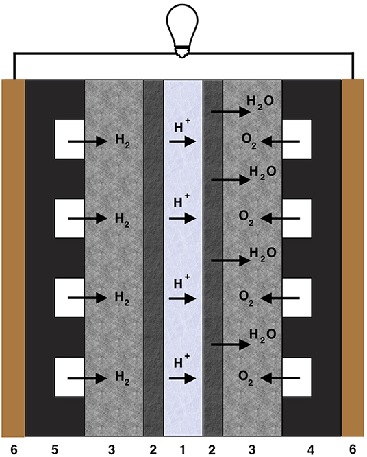
Figure 1. Schematic picture of the PEMFC. The layer thickness is given in parenthesis. For abbreviations, see text. 1—PEM (~ 50–150μ m), 2—CL (~ 10–20μ m), 3—GDL (~ 200–300μ m), 4—cathode FFP (~ 1 mm), 5—anode FFP (~ 1 mm), and 6—CCP.
The very first FC was designed in 1842 by W.R. Grove and named by him as gaseous voltaic battery (Cleveland and Morris, 2014). The term “fuel cell” was coined later, in 1889, by the chemists L. Mond and C. Langer. A breakthrough in FC development are connected with the introduction of a sulphonated polystyrene (SP) ion-exchange membrane as the electrolyte by W. T. Grubb in 1955, and by platinum deposition onto the membrane by L. Niedrach in 1958. In 1966 the SP membrane was replaced by Nafion ionomer that is in use nowadays.
The MEA itself is sandwiched between two flow field plates in a single cell or between two bipolar plates in a PEMFC stack. The flow field plate (FFP) is an important component of the cell as it supplies fuel (hydrogen, H2), and oxidant (air, O2) to the MEA, removes water, and collects electrons produced. It also provides mechanical support for the MEA (Figure 1). The FFP has several roles, for example, it separates gases between the half cells and neighboring cells in a stack; it provides an electronic conducting medium between the anode and cathode; it possesses a specific flow field design containing channels allowing even distribution of the reaction gases; it provides a solid structure for the MEA, and it facilitates water and heat management (Hamilton and Pollet, 2010).
The FFPs are fabricated from porous/non-porous graphite, coated/non-coated metal, polymer–carbon or polymer–metal composites (Hermann et al., 2005; Hamilton and Pollet, 2010). The FFP material must be physically durable, electronically and thermally conductive, chemically inert, gas impermeable, easy to manufacture, and have low-cost (Arvay et al., 2013). The graphite plates are brittle and must be manufactured rather thick to meet the durability requirements, which in turn increases their weight and cost. Metal plates can be machined very thin, but many metals are subject to corrosion when exposed to oxygen and water at high temperatures. Also, graphite is unstable and spontaneously exfoliated with respect to chemical oxidation (Skákalová et al., 2018).
Power losses in the FC depend greatly on the current density and the gas transport to the electrodes (Kjelstrup et al., 2010; Zlotorowicz et al., 2015). Losses are evaluated from the polarization curve. This is also used when someone speaks of the FC efficiency. It can be distinguished between direct and indirect losses. The direct losses are connected to the electric circuit and consist of resistance losses due to the chemical reaction (overpotentials) and ohmic resistances in the circuit. The indirect ones are connected with changes in concentration at the catalytic site, due to rate-limiting diffusion of reactants to the catalyst. Liquid water clogging the pores, will contribute to diffusional losses. Mass transport limitations can seriously affect the PEMFC performance (Li et al., 2008; Yousfi-Steiner et al., 2008; Barbir, 2013; Ous and Arcoumanis, 2013). The main role of the FFP is to prevent this type of loss, while keeping the electric and thermal conductivity high. A poor flow-field design can lead to non-uniform reactant distribution in the cell, water condensation in the cathode FFP and clogging of channels with water films and/or drops (Hussaini and Wang, 2009; Pei et al., 2016). The clogging develops gradually via the (i) single-phase flow with stray water droplets, followed by (ii) droplet flow with stable droplets, (iii) film flow with continual films of the walls and stable droplets, and finally (iv) slug flow with high water accumulation (Ji and Wei, 2009).
The PEMFC performance can also be hampered by a high local operating temperature, water management, and need for high density of catalyst. The main challenge in the development of PEMFC for automotive applications is to reduce the overall costs of the FC stack (EG&G Technical Services, Inc., 2000; Barbir, 2013). In their latest report, the US Department of Energy (April 25, 2018) announced a target price of US$40/kW for 500,000 systems per year, including 80 kW automobiles and 160 kW trucks (US Department of Energy, 2018). The FFP comprises > 60% of the weight and 30% of the total cost of the FC stack (Li and Sabir, 2005; Chowdhury et al., 2018; Pollet et al., 2019). A good design of the FFP can thus improve the overall PEMFC stack performance in terms of costs as much as 50% (Kahraman and Orhan, 2017).
The Japanese NEDO's Technology Development Roadmap 2017 (New Energy and Industrial Technology Development Organization, 2017) has as goal for 2040 to achieve a cell voltage of 0.85 V at 4.4 A/cm2 and 1.1 V at 0.2 A/cm2. According to Suzuki et al. (2019) these targets are within reach if all parts of the FC can be optimized beyond the state-of-the-art. Especially materials innovations are needed because the target operating temperature is 120°C.
Performance targets set within Europe differ from application to application (for example for use in electric cars, in trains, etc.) (Fuel Cells and Hydrogen 2 Joint Undertaking FCH 2 JU, 2018). There is a big focus on parameters like catalyst loading, system costs, durability and general cell volumetric power, and less focus on the performance curve alone as described in New Energy and Industrial Technology Development Organization (2017). The system's cost goal for 2,030 is set at €40/kW for light electric vehicles, given a power density of minimum 2 W/cm2.
China has likewise created a Roadmap for Energy Saving and New Energy Vehicles (Strategy Advisory Committee of the Technology Roadmap for Energy Saving and New Energy Vehicles, 2016). The stated goal is focused more on the cost of FC stacks in vehicles, than on the performance in terms of power density. The power density goal of a stack is set at 4 kW/L for 2030, which is much lower than the one from the NEDO's Technology Development Roadmap 2017 (6 kW/L). The cost goal however is below the one set in the current DOE target (around US$22/kW in 2030).
A comparison between what is available on the market and the progress beyond the state of the art in research is given by Gittleman et al. (2019) and Wang et al. (2019).
There is now consensus in the literature that the following properties are important for good FC performance (Arico et al., 2000; Swanepoel, 2005; Jung et al., 2006; Maharudrayya et al., 2006; van Tonder and Pienaar, 2011; Arbabi and Roshandel, 2012; Manso et al., 2012; Sousa et al., 2012)
The flow field must:
1. Uniformly deliver well-dispersed gases to the whole catalytic layers at the cathode and the anode;
2. Have sufficient rib area to provide high electronic conductivity;
3. Ensure transport of oxygen gas with a small pressure drop across the FFP;
4. Provide simple and effective liquid water removal to prevent water flooding;
5. Supply oxygen to the catalytic layer at a speed sufficient to meet demands of the cathode.
In this review, the most central flow field designs that have been proposed in the literature, will be discussed with respect to their performance on points 1–5. The most important criterion is that of uniformity in the gas distribution to and inside the GDL and in the catalytic layers. If this can be achieved with a small pressure drop, also the energy dissipation in the flow field becomes favorable. The designs are in the end compared with respect to these criteria in Table 1. The review is limited to flow field plate patterns only. Materials, design, and optimum combinations of the MEA and flow field plate are separate important problems and issues for other reviews.
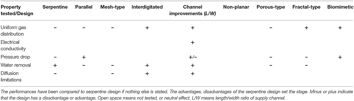
Table 1. Advantages and disadvantages of various designs tested in the proton exchange membrane FC.
The geometry of the bipolar plates is essential in yet another context. They may allow for weight reductions through thickness variations. This counts in disfavor of graphite as a FFP, as this material must be thick to avoid gas leakage and damage of the plate which must be pressed to GDL in a stack. Song et al. gives an overview about materials which can be used to create thin FFPs (Song et al., 2019).
The present review focuses on low temperature PEMFCs. For studies on the flow field pattern in high temperature PEMFCs, it can be referred to Taccani and Zuliani (2011). Hamilton and Pollet (2010) and Asri et al. (2017) gave a good overview of the different materials and coatings being used in fuel cells, including material suitability, and performance analysis.
Conventional Designs and Their Modifications
The four most common FFP designs are schematically shown in Figure 2. They include serpentine, parallel, pin-type, and interdigitated flow fields that are referred as conventional designs. Their advantages and disadvantages have been thoroughly studied (Li and Sabir, 2005). Great efforts have been devoted to design and explore flow fields that solve the flooding, current distribution, and pressure drop problems (Choi et al., 2011; Chiu et al., 2012). Besides these conventional FFPs, there are mixed designs, circular, tubular (3D), cascade (or pyramid), fractal, and biomimetic flow fields (Jang et al., 2012; Arvay et al., 2013). It has been shown that variations in the FFP design cause differences in peak power density; up to 300% difference between equivalent systems (Spernjak et al., 2010). The serpentine flow field is still regarded as the most popular choice, because of its performance, robustness, reliability, and an acceptable pressure drop (Nguyen et al., 2004; Park and Li, 2007; Jeon et al., 2008). For this reason, all the other flow fields shall be compared with the serpentine pattern.
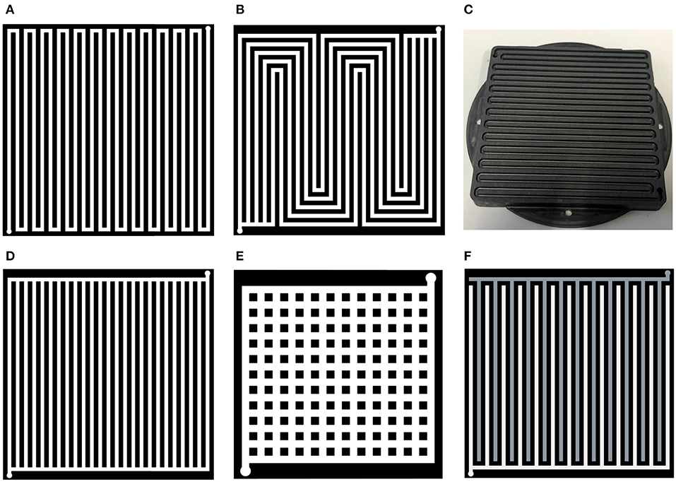
Figure 2. Schematic pictures of conventional FFP designs: 1-channel serpentine (A), 5-channel serpentine (B), parallel (D), pin-type (E), interdigitated (F), and a photo of the 1-channel serpentine with 50 × 50 mm FFP (C); the inlet channels are marked in white the outlet ones are in gray.
Serpentine Design
The traditional serpentine design (Figures 2A,C) has a single continuous channel covering the whole area of the FFP. A single inlet is connected to a single outlet. The reactant gases move everywhere from the FFP through porous GDL via under-rib paths. The serpentine design has emerged as an industry standard because of its robust performance and ability to reproduce results (Suresh et al., 2011). It is used as a reference design, to assess any improved or new designs of FFP. Though water accumulates in the downstream channels, and there are short bends (Wang, 2004; Li et al., 2007; Jeon et al., 2008), the serpentine topology reduces the risk of flooding in the channel because liquid water can be pushed out. A gas exposed to a relatively high-pressure drop will accomplish this (Arvay et al., 2013; Kahraman and Orhan, 2017). The column for the serpentine design in Table 1 has therefore a plus for water removal. The serpentine flow field is suitable for both small and large active membrane areas (Zhang et al., 2011; Park et al., 2012; Kahraman and Orhan, 2017; Ozden et al., 2017; Ouellette et al., 2018). This is because it provides good under-rib convection in the GDL due to the relatively high local pressure drop between consecutive channels (Nam et al., 2009; Zhang et al., 2011; Park et al., 2012; Kahraman and Orhan, 2017; Ozden et al., 2017; Ouellette et al., 2018). It also provides a stable performance due to its good mass transfer and reactant distribution capabilities across the flow channels (Jung et al., 2006; Choi et al., 2011). Furthermore, it gives a relatively smooth temperature distribution.
The disadvantages of the serpentine designs are a high resistivity to flow due to the long narrow channel and presence of short bended channel paths (Tüber et al., 2004; Jeon et al., 2008; Kloess et al., 2009; Suresh et al., 2011). At low current densities, water can be accumulated below the ribs of the FFP, while at higher current densities this can also happen in the channels (Figures 2A,B). Serpentine flow channels for the reactant gas streams and coolant flows produce a low-temperature region near the channel inlet, and a high-temperature region near the outlet (Li et al., 2007). The problem of high-pressure drops has been partially solved using a smaller-sized PEMFC and by optimization of the channel and base dimensions (see below) (Zhang et al., 2011; Park et al., 2012; Kahraman and Orhan, 2017; Ozden et al., 2017; Ouellette et al., 2018). There is often a non-uniform reactant distribution in the GDL due to reactant depletion along the channel (Zhang et al., 2011; Park et al., 2012; Kahraman and Orhan, 2017; Ozden et al., 2017; Ouellette et al., 2018). A partial solution to these disadvantages was obtained by multi-path serpentine geometries (Figure 2B) and smaller sized PEMFC. For instance, for commercial FFPs with dimensions 50 × 50 mm, the design is based on five parallel channels of width W = 1 mm and depth D = 1 mm each, see Figure 2B. In this design the gas moved in a serpentine manner through 5 parallel paths from the inlet to the outlet at the corners of the FFP (round holes in FFP) making 4–5 turns only. In comparison to the single channel serpentine, this design has channels with 4–5 times shorter lengths and therefore, smaller pressure-drop governing the flow; better water removal from the channels; more uniform gas distribution and, in that way, higher performance. Location of the inlet/outlet and the type of their connection to the parallel channels also influences the FC performance (Belchor et al., 2012).
The disadvantages of such designs remain similar to those for the single channel serpentine (Nam et al., 2009; Zhang et al., 2011; Park et al., 2012; Arvay et al., 2013; Kahraman and Orhan, 2017; Ozden et al., 2017; Ouellette et al., 2018):
1. Non-uniform reactant distribution in the GDL due to reactant depletion in the short bends and along the channels;
2. A relatively high pressure drop across long length, parallel channels, and in the short bends when the flow gets rotated at 180°.
During the last 15 years there have been many attempts to improve the FFP design and obtain more uniform distributions of reactants and better water removal at reasonable low pressure drops. The relative efficiency of the single-and multi-channel serpentine geometry depends upon their detailed shape and the flow regime. The shape is determined by the W and D of the channels and the distance between them (rib or base, B). In the single-serpentine design sub-rib convection presents under all ribs because of the pressure difference between them. Therefore, the sub-rib convection significantly influences the FC performance especially when the O2 supply or membrane moisture content is limited, and the influence almost does not depend on the aspect ratio (AR = D/W) (Wang et al., 2009). In the multi-pass serpentine FFP the sub-rib convection between the parallel channels is lower due to small pressure differences. At operating voltages < 0.7 V, the reduced channel AR < 1 increased the reactant inlet flow velocity, enhanced liquid water removal, and promoted O2–transport to the GDL. For both designs, the cathode pressure drops increase as the channel AR decreases. They also found that the low external and internal heat transfer coefficients increased the temperature inside the PEMFC and led to too strong sub-rib convection. The combination of high temperature and sub-rib convection may cause PEM dry-out and rapid decrease in the PEMFC performance (Wang et al., 2009).
Different numbers of the parallel channels in the serpentine design have been studied. For commercial FFPs, with 200 cm2 reactive area, the 26-channel serpentine flow field gave the best performance and the lowest “pumping power” because the channels became reasonably short and the bends were longer compared to the single channel design (Shimpalee et al., 2006). The multi-path geometry decreased the risks of water accumulation and decreased the pressure drop. Two types of interconnections of the 26 channels of W × D = 0.9 mm × 0.55 mm, and B = 0.9 mm have been studied. It was shown that the shorter path resulted in a more uniform temperature and current distribution and less condensed liquid water accumulation than in the longer path. The 13-channel serpentine FFP geometry has as advantage of its overall performance in comparison with the 26-channel, 6-and 3-channel, due to smaller differences in PEM hydration. The membrane water content and its uniformity are key factors for a low ohmic membrane resistance (Shimpalee et al., 2006).
Serpentine geometry with tapered, constricted, stepped, and asymmetric channels exhibited (Kahraman and Orhan, 2017): (i) improved performance under low cell voltage, (ii) improved mass transport, and (iii) improved water removal. However, these geometries exhibit high pressure drops and are vulnerable for flooding in the downstream channels and short bends (Wang, 2004; Li et al., 2007; Jeon et al., 2008).
The mixed serpentine designs like split with mirror or double-mirror locations were aimed at an intensification of mixing of the reactants at every turn of the channels. The advantages are (Kahraman and Orhan, 2017; Kahraman et al., 2017) as follows: (i) high uniform reactant distribution, and (ii) lower pressure drop in comparison to the single channel serpentine. The disadvantages are the same as for single and multiple-path serpentine geometries. The mirror-serpentine designs have been recommended for large active MEA areas, because the flow field can be split into smaller independent flow-field cells with their own inlets and outlets. That lead to: (i) a decrease in the pressure drop, and (ii) a more uniform reactant distribution in comparison to the non-split serpentine design over the entire MEA area.
Waved channels for the serpentine design (Figures 3A,B) were found to be better for reactant transport and water removal because they allow a variation in the local flow along the waved walls (Li et al., 2017). The 3D CFD computations revealed that slopes of 30 and 45° were more efficient than slopes 0 and 15°. The finding was confirmed experimentally. Since the slope 45° exhibited a higher hydraulic resistivity, the value 30° was recommended for the cathode FFP.
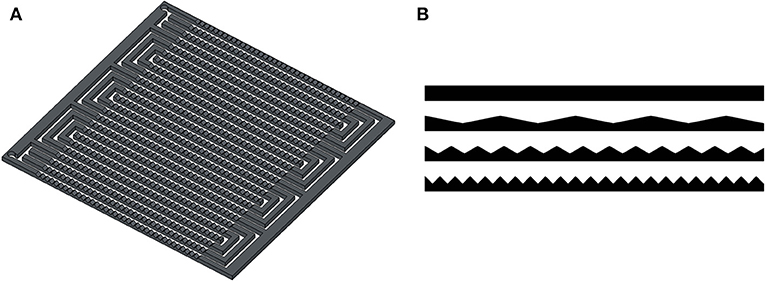
Figure 3. 3-channel serpentine FFP with waved channels (A). A cross-sectional view is shown in (B) [sketched after (Li et al., 2017)].
A summary of results on the serpentine flow fields is shown in the first column of Table 1. The minuses are due to liquid water that tends to accumulate in the short bends of the serpentine channels, and the relatively high and variable pressure drop that can cause uneven gas diffusion from the FFP into the GDL. The design is favorable with respect to water removal.
Parallel Design
The parallel design, first patented by Pollegri and Spaziante (1980), has multiple parallel paths from the inlet to the outlet without bends (Figure 2D) in order to decrease the hydraulic resistivity of the flow-field. It was found that this geometry reduced the pressure needed to maintain a constant flow rate at the inlet (Hontañón et al., 2000; Lobato et al., 2010). This feature can be beneficial for the entropy production rate, but low pressure at the outlet side may not be able to push out the condensed water. Therefore, water droplets appeared, grew and finally blocked the flow-field channels. This led to a non-uniform distribution of reactant gases and temperatures, which again reduced the life of the system and the overall performance. Parallel designs usually demonstrate the lowest overall performance among the conventional designs (Wang et al., 2008; Kandlikar et al., 2009; Oliveira et al., 2010; Lu and Reddy, 2011; Kahraman and Orhan, 2017; Ouellette et al., 2018, p. 32). Results for these designs are summarized in Table 1, column two.
Some modifications of the parallel design are shown in Figures 4A–C. Several variations including one multi-path (Figure 4A), two narrow and two multi-tube (Figure 4B) inlets and outlets with different widths of the transverse and longitudinal channels have recently been proposed (Lim et al., 2017). The increased width of the outlet channels created a larger pressure drop at the distal ends of the channels, pushing out water. CFD simulations showed that the proposed designs yielded a more uniform flow distribution, as well as gradual pressure reduction from the inlets to outlets, both increase the PEMFC performance. The single inlet/outlet design generated more uniform reactant distribution than the double inlet/outlet designs.
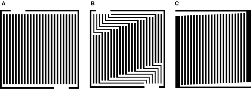
Figure 4. Examples of modifications of the parallel design: one multi-path inlet/outlet (A), several multi-paths (B) and inlets/outlets of a constant width with a gradually decreasing inlet channel (C).
The parallel design with gradually decreasing inlet channel width (Figure 4C) gives high flow rates through the secondary channels in the mid portion of the FFP. Thus, in this design ~60–70% of the flow passed through the initial 80% of total flow-field area (Hossain et al., 2017). The smoother branching angles of the secondary channels produced lower hydraulic resistivity and therefore smaller energy dissipation. The central location of the outlet provided a better flow distribution compared to conventional parallel channel flow field.
So-called Z-shape designs with the parallel channels located in the Z-shape (Figure 4B) have some advantages over the parallel ones (cf. Table 1): (i) lower pressure drops, (ii) uniform distribution of single-phase and two-phase flow and absence of plugs, (iii) lower parasitic power for the air supply system; and (iv) higher overall efficiency (Ashrafi et al., 2018).
Mesh-Type Design
Mesh-type (pin- or grid-type) designs are composed by two orthogonal sets of parallel channels (Figure 2E) allowing two-directional flows (Lobato et al., 2011; Manso et al., 2012; Guo et al., 2013; Ouellette et al., 2018). Such designs provide a much lower pressure drop than the serpentine design, since the water accumulation at the cathode FFP becomes lower than in the parallel designs, meaning that the number of droplets blocking an individual channel are reduced (Arvay et al., 2013). The main advantage of the mesh-type design in comparison to the serpentine and other conventional designs, is the low pressure drop, due to a relatively low hydrodynamic resistivity of the interconnected channels. The disadvantage is an uneven flow distribution and appearance of stagnant areas (see Table 1). The disadvantages can be related to the presence of a variety of different routes for flow from the inlet to the outlet. The routes located close to the diagonal of the FFP have the lowest resistivity and, thus, the highest flow rate. This altogether leads to Lobato et al. (2011), Manso et al. (2012), Guo et al. (2013), Kahraman and Orhan (2017), and Ouellette et al. (2018) (i) inhomogeneous reactant distribution when the corners far from the inlet and outlet remain almost without reactant, (ii) inhomogeneous condensed water removal, (iii) inhomogeneous current density distribution, (iv) low PEMFC power efficiency (power density values are much lower than in the serpentine designs for the same flow regimes; Hsieh and Huang, 2008).
A prolonged PEMFC operation with mesh-type FFP at high flow rates can lead to complete flooding of the FFP. To overcome the problem, the designs have been modified with additional areas outside the active area, to help the gas coalesce with water droplets (Figure 5A) (Kahraman and Orhan, 2017). Using smoothly varying channel widths (Figure 5B) (Guo et al., 2011; Arvay et al., 2013), and gradually decreasing channel widths (Figure 5C) (Guo et al., 2013) the problem was overcome. Assuming Poiseuille flow with uniform reactant consumption in each node of the mesh, the optimal widths of the nodes for the minimal flow variations in the nodes over all the system were computed. It was shown this geometry could increase the PEMFC performance by ~10%.
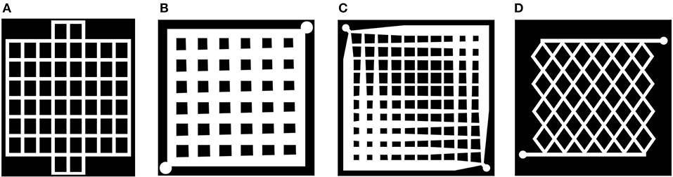
Figure 5. Sketches of mesh-type design modifications: with additional areas helping the gas coalesce with water droplets, from (Kahraman and Orhan, 2017) (A), with gradually increasing/decreasing, from (Guo et al., 2011) (B) and optimized, from (Guo et al., 2013) (C) channel widths, and intersectant geometry, from (Wang et al., 2008) (D).
Recently a non-rectangular intersectant geometry (Figure 5D) has been tested based on a theoretical model and on the experimental setup for a metallic FFP (Dong-Hui et al., 2017, 2018). The optimal dimensions and porosity per unit length were determined as 0.6 × 0.3 mm and 0.5, respectively. The intersectant design at the optimal operating parameters, 300 ml/min for the hydrogen flow, 500 ml/min for the air flow, and at operating temperature of 80°C, exhibited better performance than the standard single channel serpentine design (see Table 1).
Interdigitated Designs
Interdigitated flow-field geometries do not have a continuous path from the inlet to the outlet, so the channels have dead-ends (Figure 2F) (Hu et al., 2004). Such designs are aimed at forcing gas flow delivery through the GDL to the reaction sites in the MEA and remove water more efficiently (Arvay et al., 2013). It was shown that generally, interdigitated designs performed better than parallel designs, but worse than serpentine ones (Hu et al., 2004; Spernjak et al., 2010). The corresponding differences depended on flow conditions (Zhang et al., 2009). Interdigitated designs seem to be able to manage water removal better than parallel designs, without the excessively large pressure drops proper to serpentine designs (Jang et al., 2012).
The advantages of the interdigitated design (Wang et al., 2008; Oliveira et al., 2010; Zhang et al., 2011; Kahraman and Orhan, 2017; Ozden et al., 2017; Ouellette et al., 2018) are as follows: (i) efficient water removal due to forced under-rib convection in the GDL (high pressure drop), and (ii) high performance at high current densities when water production is significant. The disadvantages are: (i) this type of FFP has the highest resistivity and pressure drop among all designs due to disconnected channels, (ii) the PEMFC performance is strongly determined by GDL properties, (iii) possible long-term damage to the GDL and MEA from excessive convective forces (see Table 1).
Some modified interdigitated designs with varying (both decreasing and increasing) widths of the parallel channels from central to lateral ones with two (Figures 6A,B) and three (Figure 6C) inlets and different number of parallel channels may be beneficial, due to their reduced pressure drop and improved current distribution compared to conventional interdigitated design (Figure 2F). Variation of the widths, depths and rib width values within wide ranges, reveals designs with lowest pressure drops and highest performance (Arvay et al., 2015).
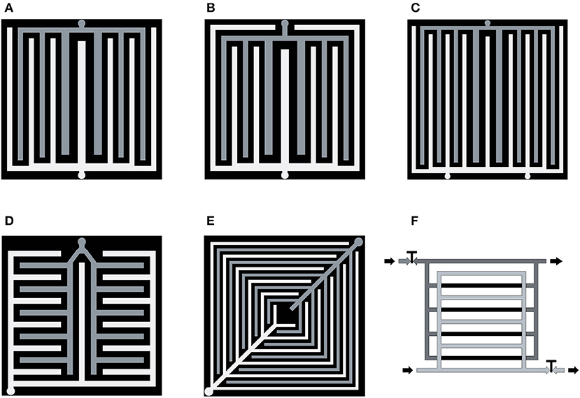
Figure 6. Sketches of modifications of interdigitated designs: with two inlets (A) and perimeter channels (B), with three inlets (C) from Arvay et al. (2015), non-fractal lung-type (D) and leaf-type (E) from Kloess et al. (2009), switched parallel-interdigitated type (F), from Santamaria et al. (2013).
Two interdigitated designs (Figures 6D,E) are biologically inspired. They mimic the lung (Figure 6D) and the plant leaf flow conduction systems (Figure 6E) (Kloess et al., 2009). 3D numerical computations revealed that both designs can produce up to 30% more in peak power density in comparison with conventional interdigitated (Figure 2F) and single-channel serpentine (Figure 2A) designs, with the same dimensions of the channels and bases. It was shown by CFD simulations and experiments at operating temperatures T = 65–75°C, 2 atm back-pressure, and 100% relative humidity (RH), that the leaf design (Figure 6E) performed better than the lung-type design (Figure 6D). A comparative experimental study of different combinations of 5-channel serpentine, lung-based (Figure 6D), and leaf-based (Figure 6E) designs showed that the lung-based structure displayed the lowest performance under all tested operating conditions (Ozden et al., 2017).
The synthetic design (Figure 6F) can be switched from classical parallel to interdigitated and vice versa by closing/opening of the taps (T) (Santamaria et al., 2013). It was shown by experiments that the parallel flow field regime produced higher system power and lower water at lower current densities. At high current densities, when water production was significant, the interdigitated design was more efficient for water removal and higher performance of the FC.
In principle, one could use different designs for the anode and cathode FFPs. Combinations of serpentine (S) and interdigitated (I) FFP designs S-S, S-I, and I-S for the anode and cathode, respectively, have been tested (Ouellette et al., 2018). It was found that the best performance could be achieved when the serpentine FFP was used at the anode and the interdigitated FFP at the cathode. The highest reactant uniformity in the catalyst layer (CL) was observed in the S-S and S-I configurations.
Improvement of the Channel Geometries
Variations in Dimensions of the Channels and Ribs
High impact of the 3D- nature of gas and water channels in the FFP system on the FC efficiency has been confirmed by experiments and numerical simulations. In the 3-channel serpentine FFP the decrease in the channel depth from W = 1.0–0.3 mm linearly increased the FC performance due to lower water accumulation in the channels confirmed by experiments on a transparent FFP (Hwang et al., 2008). The decreased channel depth leads to an increase in the linear velocity of the reactants and products at the same flow rate that, in turn, improves water removal.
The ratios between W, L, and B have also a great effect on the reactants flows, pressure drop, water removal, mechanical stiffness, temperature distribution, as well as on the electrical conductivity (Sadiq Al-Baghdadi, 2008; Wang et al., 2010a). It is recalled that the flow channels are used for water and heat removal, reactants delivery and distribution to/in GDL and CL. The space between the flow channels is used for heat/mass transfer, electric current collection, and transmission. Different strategies to improve the water/heat management and PEMFC efficiency by changing the channel path length, rib width B, and rib/channel width ratio B/W have been proposed (Shimpalee et al., 2006; Manso et al., 2012; Wawdee et al., 2015).
An experimental study of the flow interactions in the adjacent micro-channels, revealed that under-rib convection has an essential effect on the PEMFC performance arising from the local electricity collection under either the inlet channel or the rib areas (Chen et al., 2017). The rib areas possessed the highest current density when sufficient pressure differences were applied to the FFP. The inlet channel always exhibited a higher current density than the outlet channel, possibly due to its higher gas concentration. The existence of an optimal pressure drop in the flow field was documented, when the current density under the inlet channel and the rib areas reached its maximum. The 3D CFD computational results showed that significant temperature gradients exist within the PEMFC, with temperature differences of several degrees within the MEA (Berning et al., 2002). This was explained by charge transport under the collector plates. A major impact on the current distribution as well as the predicted limiting currents was also seen. The 6- and 10-channel serpentine flow fields with different combinations of the channel dimensions W = 0.5 and 0.9 mm, D = 0.5 and 1 mm, B = 0.5 and 0.8 mm have been studied with isothermal two-phase 3D models (Wang et al., 2017). It was shown that the PEMFC performance can be increased by using narrower channels and smaller cross sections (Kreesaeng et al., 2015; Wang et al., 2017). At low current densities when water starts to accumulate in the GDL at under-rib regions, the under-rib convection plays a more important role for water removal, than the pressure drop does. At high currents, water starts to accumulate in the channels and the pressure drop becomes more important for water removal and promotion of the oxygen transport to the catalyst layer.
Some of the proposed designs have led to a higher pressure drop (Shimpalee and Van Zee, 2007), lower PEM hydration and conductivity, ineffective heat and water management (Shimpalee et al., 2006). The general conclusion is that wider ribs and shorter and narrower channels improve the reactant distribution in the GDL (Shimpalee et al., 2006; Manso et al., 2012). Nevertheless, the influence of the L/W ratios on the flow parameters and FC performance revealed some contradictions (Shimpalee et al., 2006; Manso et al., 2012; Chowdhury et al., 2018). For instance, the ratio L/W>1 is favorable for:
◦ Mechanical support of flow field for PEM and GDL;
◦ High membrane water content;
◦ Good electrical conductivity;
◦ Fast heat transfer from the membrane;
◦ Uniform current distribution in MEA;
◦ Uniform temperature distribution in MEA;
◦ Better PEMFC performance at high current densities;
while the ratio L/W<1 is favorable for:
◦ Lower pressure drop across the flow fields;
◦ Larger contact area between the reactants and the GDL;
◦ Better water removal from the GDL;
◦ Lower total cell voltage losses.
Additionally, the width/rib (W/B) ratio influences the same main features of the PEMFC efficiency and make the problem of the FFP optimization even more ambiguous. In Goebel (2011), the importance of the width of the ribs was demonstrated, and the best performance of the PEMFC was detected for W/B = 0.25/0.25 mm value within the limits B = 0.25–1 mm. FFPs with shallow channels exhibited higher performance than the deep ones. The reason for this was that shallower channels have a higher-pressure difference between adjacent channels than deeper channels, leading to an increase in O2 transport due to higher under-rib convection (Inoue et al., 2006). The forced gas delivery led to better performance when the FFP had tapered channels (Liu et al., 2006).
For some channel designs, the reactants were removed too quickly from the CL, leading to appearance of dead zones with low energy production (Ouellette et al., 2018). In conclusion it can be said that multi-criteria optimization approaches are important for design improvements. Some designs for optimal pressure drop and cooling efficiency have been discussed in Alizadeh et al. (2016).
Similar conclusions have been derived in the experimental study of 44 cm2 graphite cathode plates with four single serpentine geometries of 1 mm channel depth and various widths of 0.5, 1, 1.5, and 2 mm (Zhang et al., 2019). The number or the parallel paths were 43, 31, 27, and 23, accordingly. It was found that the cell performance always increased with a decrease in the rib width and an increase in the inlet flow rates in the channels when the provided pumping power was not taken into consideration. However, when pumping power was accounted for, the net power density reached a maximum at different combinations of rib widths and reactant flow rates depending on the cell voltage.
Numerical simulations revealed that a maximum current density j = 1.04 A/cm2 could be achieved at B/W = 0.25/0.25, but the anode/cathode pressure drop in this case became very high [~15/92 Pa (anode/cathode) for 25 mm channel length] (Chowdhury et al., 2018). A low pressure drop along anode/cathode channel Δp ~2/6 Pa was reached at B/W = 0.25/2.0, but in this case the current density was only 0.79 A/cm2 and the ohmic resistance was very high. Therefore, an intermediate value B/W = 1.0/1.0 mm was proposed as an optimal one, giving the current density 0.9 cm2, and the anode/cathode pressure drop of Δp ~3/11 Pa (Chowdhury et al., 2018). The ohmic losses from the interfacial contact between the FFP and GDL increased monotonously with the B/W ratio, while the loss due to diffusion in the GDL remained negligible. The impact of the FFP on the polarization curve rapidly decreases at B/W < 0.2 and slowly decreases at B/W > 0.2. As a result, the total voltage loss is at its minimum at 0.4<B/W<0.6.
Variations in Cross-Sectional Shape
Variations in the geometry of the serpentine design and the shape of the channels have been studied theoretically and experimentally. Circular (Sadiq Al-Baghdadi, 2008; Mohammadi-Ahmar et al., 2016), annular (Khazaee and Ghazikhani, 2011), semi-circle (Kumar and Reddy, 2003a), trapezoidal (Sun et al., 2006), and triangle (Owejan et al., 2007) cross-sectional shapes of the channel have been proposed and tested.
Numerical computations on the FFP with dimensions 40 × 40 mm with 20 channels of the same W = 1.5 mm and square, triangle, and semicircle cross-sections in a serpentine design have been carried out (Kumar and Reddy, 2003a). It was shown for the same inlet flow rates, that the pressure drop was lower in the rectangular shape and higher in the semi-circle channels. Hydrogen consumption was 84.8% in the rectangular, 92.5% in triangular, and 92.9% in the semi-circular channels, i.e., the latter was more efficient. O2–consumption was maximal at D = 1.5 mm, i.e., in the quadratic cross-sections. Therefore, simultaneous demands for minimum pressure drop and high H2-consumption are contradictory. A two-criterion optimization approach could determine optimal W × D dimensions and cross-section shape. The problem formulation in Kumar and Reddy (2003a) is incorrect because the chosen cross-sections (square W × D =1 × 1 mm, equilateral triangle W = 1 mm, and semicircle D = 0.5 mm) possess different hydraulic resistivity and lateral surfaces for the mass and heat exchange.
The rectangular and triangular shapes of the same width and cross-sectional area were compared in experiments (Owejan et al., 2007). Both cathode and anode FFPs had the 5-channel serpentine design with four short bends (Figure 2C), and the anode plate was turned at an angle of π/2 reathode plate. It was found that the condensed water was mostly trapped in the two corners adjacent to the GDL; therefore, the channels with triangular geometry retain less water than rectangular channels. When the GDL with lower in-plane gas permeability was used, a smaller amount of the retained water was detected.
With a 3D non-isothermal model of the flow-field, using a genetic algorithm to study the optimization of channel configuration, it was found that the trapezoidal shape was better than the square shape 1 × 1 mm with the same cross sectional area (Zeng et al., 2017). The optimal dimensions (W = 1.3 mm, D = 1.1, and bottom width 0.89) increased the productivity of the PEMFC by 10.92% at an operating cell voltage of 0.4 V.
Additional Improvement Measures
The channels could also be modified by an additional slant up or down related to the plane of the FFP. The down-slanted (at the angle of 20°) parallel channels in the 5-channel serpentine design of the anode FFP increased the PEMFC performance (Bunmark et al., 2010). The down-slanted channels increased water back diffusion from the cathode to anode, decreased the concentration of condensed water in the anode GDL and CL, leading to PEM hydration and higher PEMFC performance especially in the medium current region. The same modifications of the cathode FFP led to intense water draining from the cathode side leading to PEM dehydration and reduction in the PEMFC performance. The up slanted anode or/and cathode channels induced flooding and low performance. Similar results have been obtained on the 35° slanted channels (Wawdee et al., 2015).
Mixed and Non-Planar Designs
There are many experimental and theoretical studies of different modifications of conventional designs, including different numbers (Jeon et al., 2008; Boddu et al., 2009), and dimensions (Kumar and Reddy, 2003a; Ferng et al., 2008; Ferng and Su, 2007; Wang et al., 2010b) of inlets, outlets, and channels, smoothed corners, and other improvements. Mixed designs are based upon combinations of two or more of the convenient designs like parallel-serpentine, mirror-serpentine, serially linked serpentine (Kahraman and Orhan, 2017), spiral-serpentine (Tang et al., 2010), split-serpentine (Suresh et al., 2011), and others. Some of them managed to enhance under-rib convection, improve water removal, and FC performance noticeably (Suresh et al., 2011).
Several tubular designs presented by the usual sandwich-type FC composition (Figure 1) rolled into a cylindrical (Khazaee and Ghazikhani, 2011; Saghali and Mahmoudimehr, 2017) or conical shapes have also been proposed (Mohammadi-Ahmar et al., 2016). The cone geometry was estimated as more efficient in comparison to the cylindrical one with the same design (serpentine or parallel) of the flow-field.
Circular Geometry of FFP
Other less common approaches include radial (Figures 7A–C) (Cano-Andrade et al., 2010; Friess and Hoorfar, 2012) and spiral (Figure 7D) (Juárez-Robles et al., 2008) designs for circular FFPs and PEMFCs. A radial flow-field design was developed for a circular, tablet-type PEMFC. The reactants enter the flow-field through a tube in the middle of the circular region (Figures 7A–C) and move through the radial channels to the perimeter. In some of these designs (Figures 7A,B) (Perez-Raya et al., 2010), radial channels are linked by circular ones that are used to keep the pressure drop even across the channel length. The number of the radial channels could be different. A numerical analysis of three radial flow configurations with 4, 8, and 12 radial channels revealed that the 4-channel model had the best performance, i.e., the highest current density production at the lowest pressure drop along the channel length (Cano-Andrade et al., 2010). The best gas velocity range 0.03 m/s < v < 0.04 m/s allowed fast flow without any stagnation and flooding at reasonable low pressure drops.
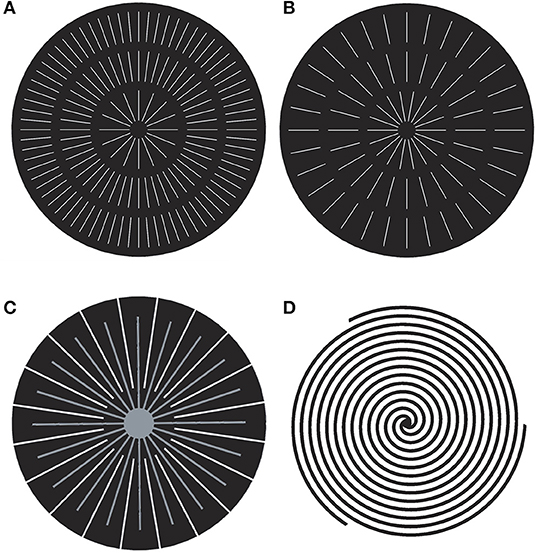
Figure 7. Sketches of radial designs: with 16-48-72 (A) and 18-24-32 (B) radial and 2 circular channels, with 20 pairs of radial interdigitated channels (C), from Friess and Hoorfar (2012), and 3-channel spiral design (D), from Juárez-Robles et al. (2008).
In other designs, the inlet and outlet channels are not connected (Figure 7C). This mixed radial interdigitated design provides additional smoothing of the reactant- and temperature distributions, due to intensified mixing in the space between the two systems of the interdigitated inlet and outlet channels. The short paths of the radial designs provide very low resistance and, thus, pressure drop. Due to the same reason, the water removal is better, and a higher mass-transport, current density, and better performance can be obtained (Cano-Andrade et al., 2010; Friess and Hoorfar, 2012; Kahraman and Orhan, 2017). A better performance was achieved even when the pressure drop was kept twice as low as that in the square FC with the serpentine FFP (Friess and Hoorfar, 2012), leading to the assessments in Table 1.
The radial flow-field design is still under development and not well-documented by experiments. There are disadvantages connected with the presence of the distributed system of outlets at the perimeter. This increases system complexity especially when the PEMFC is integrated into a full stack. That may also produce instability, if one or several outlets become clogged by condensed water (Friess and Hoorfar, 2012). In dry air with radial flow-fields, the PEM is susceptible to drying. The problem can be solved by humidification of in the environment. Large ohmic losses are also among the disadvantages of the radial design.
Spiral flow field geometry has also been developed for the circular region (Gurau et al., 2003; Juárez-Robles et al., 2008), but the relatively long spiral channels need higher pressure than the parallel or synthetic designs do. An improved design with multiple concentric spirals (Figure 7D) decreases the hydraulic resistivity of the channels by decreasing their lengths. CFD computations on spiral designs with 1–8 channels, showed that the model with 4 spirals exhibited more uniform distributions of reactants and current density, larger power generated, and relatively small pressure drops (Juárez-Robles et al., 2008). The model with 8 spirals demonstrated the worst performance.
Porous Type FFPs
The porous materials provide better drainage of the condensed water that is advantageous at high current densities (Tabe et al., 2013; Kozakai et al., 2016), and more uniform reactant gas distribution compared to the FFPs with channels (Hontañón et al., 2000). The foams, meshes and fibrous porous materials have been tested as candidates for the FFP (Kumar and Reddy, 2003b; Tang et al., 2010).
Metal meshes and foams are easy to manufacture; they provide a uniform flow distribution over the MEA and even distribution of the current density, but they are vulnerable for corrosion and need special anti-corrosion and hydrophobic coating that is not such stable and durable like titanium and graphite (Arvay et al., 2013). Unlike the foams, meshed materials have a regular porous structure with single or dual porosity and are easier for manufacturing, while in the foams identical porosity properties are difficult for reproduction. Due to their plane construction the meshes have a better controllable contact area with GDL than the foams. Meshed FFP demonstrated good performance at limited current ranges. Smaller pores lead to more uniform reactant distributions but higher hydraulic resistivity and water accumulation. Therefore, the optimal design satisfying the main performance criteria for the FCs (see section Introduction) is difficult for elaboration due to numerous disadvantages (Mallick et al., 2016; Yuan et al., 2016; Kahraman and Orhan, 2017; Ouellette et al., 2018). The flow resistance could be decreased by optimizing the porosity of materials. Thus, the highly porous material with ~85% porosity and double peak in the pore diameter distribution with maxima at d~150 and ~30 μm exhibited the smallest gas diffusion resistance at a high current density operation among other materials (Kozakai et al., 2016).
Fractal Type Design
The first multichannel fractal design of the PEM and direct methanol FCs was proposed in 2004 (Tüber et al., 2004) (Figures 8A,B). It was based on a combination of fractal distributing and parallel delivering channels. A combination of fractal distributing and serpentine delivering channels has also been tested (Wang, 2015). By a fractal approach, it is meant that the diameters and lengths of the channels of the consecutive generations are related by the scaling laws
where a and b are constants for self-similar scaling. The algorithm that generates the structure is designed to fill in a given area of rectangular shape (Figures 8A,B), Z-shape or other shapes. The diameter ratios in the junctions were not determined in Tüber et al. (2004). Under some operating conditions with low water condensation, the PEMFC with fractal structure FFP (Figures 8A,B) exhibited better performance than the serpentine (Figure 2A) and parallel (Figure 2D) designs, mainly due to the lower hydraulic resistivity of the fractal structure (Tüber et al., 2004; Liu and Li, 2013). Anyway, the fractal system was found to be vulnerable for blockage of the channels by water, leading to non-uniform reactant distribution. Therefore, the PEMFC performance with fractal channels was higher than the conventional parallel design, but lower than the conventional serpentine design (Tüber et al., 2004), cf. Table 1.
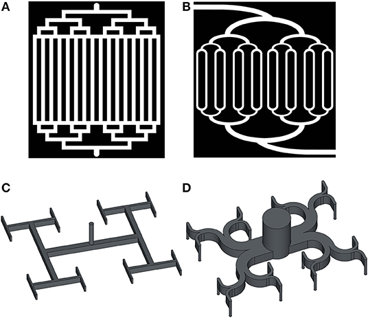
Figure 8. Sketches of the fractal type designs for FFP: open channels fractal+parallel with sharp (A) and smoothed (B) angles (from Tüber et al., 2004), and closed channels fractal tree with sharp (C) and smoothed (D) branching angles, from Luo and Tondeur (2005).
A uniform gas delivery to the MEA active area could be achieved with a binary tree fractal with branching angle α = π (Figure 8C). Rectangle channels in such designs can easily be engraved in a graphite plate. Designs with different number of generations with N = 16–64 outlets, have been studied theoretically and experimentally (Damian-Ascencio et al., 2007; Fan et al., 2008; Ramos-Alvarado et al., 2011).
The dimensions of the channels were computed based on the optimization approach
where W is the viscous dissipation and v is the volume. Such design corresponds to minimum entropy production at isothermal conditions (Kjelstrup and Røsjorde, 2005; Kjelstrup et al., 2010). Due to asymmetry of the streamlines at the branching and rather short lengths of the tubes, the resulting flow in the multiple outlets will not be uniform. The flow non-uniformity has been estimated by the parameters:
where Qj are flow rates in the n=1,…,N outlets, Qmax, Qmin, Qavr are the maximum, minimum and average values of the flow rate.
In the model with N = 16 outlets, presented in Figure 8C, q increased from 0.001 to 0.055 and θ increased from 1.003 to 1.014 when the Reynolds (Re) number increased from Re = 150 to 650 (Ramos-Alvarado et al., 2011). In the model with N = 64 outlets, q increased from 0.0002 to 0.0013 and θ increased from 1.002 to 1.007. Therefore, the model with N = 64 outlets produced a more uniform flow distribution at the lowest pressure drop and energy dissipation. The fractal system with 256 outlets was found to have the highest uniformity of the flow and consequently the current distribution (Ramos-Alvarado et al., 2011), but the overall PEMFC performance was lower than in the convenient parallel design (Fan et al., 2008; Lorenzini-Gutierrez et al., 2013; Kahraman et al., 2017; Ouellette et al., 2018).
The angles in the bifurcations can be smoothed, and in that way a more efficient fluid distribution system (Figure 8D) can be obtained. It was shown by Lattice Boltzmann simulations that the optimized distributor has between 15.9 and 25.1% lower pressure drop than one with sharp angles (Figure 8C) (Wang et al., 2014). The fractal-type flow fields composed by n parallel plates with a network of interconnecting channels are called “pyramidal” (Senn and Poulikakos, 2004; Fan et al., 2008). In the case n = 3 the FFP is presented by three parallel plates with one tubular inlet, planar tree-like fractal system and tubular outlets. Similar 3D binary trees with sharp and smoothed branching angles have been tested (Luo and Tondeur, 2005). Such structures are not good for PEMFCs because the thickness of the graphite layers increases both weight and cost of the FC.
At higher Re numbers the non-uniformity increased, and when Re increased from 1,020 to 2,247, q increased from 0.050 to 0.069 and θ increased from 1.170 to 1.252 (Fan et al., 2008). However, the disadvantages of the fractal design are as follows: (i) vulnerability for blocking one or two outlets by liquid water. This makes the gas flow and generated current non-uniform; (ii) large widths of the first generations of the channels are unfavorable for the under-rib convection (see Variations in dimensions of the channels and ribs), and this decreases the FC performance; and (iii) manufacturability problems are essential for the smallest channels.
Bio-Mimetic Designs for FFP
During the last decade, novel types of FFP designs, inspired by nature and mimicking the structure of biological transport networks, have been elaborated (Tüber et al., 2004; Kloess et al., 2009; Ramos-Alvarado et al., 2011; Roshandel et al., 2012; Arvay et al., 2013; Guo et al., 2013, 2014). The idea has been that the FFP in PEMFC should mimic the transport function that can be seen in blood vessels, bronchial airways, and fluid conducting vessels in plants. These biological structures deliver fluids, gases or their mixtures to porous structures (tissues, lungs, wood, or GDL), and uniformly distribute them over a given volume. Over time on Earth, optimal structures and systems in plants and animals have evolved, including fluid delivery systems that are constructed as branched networks; each conducting element with diameter do is split into k daughter elements with diameters d1,….,d1 satisfying the relationship:
Murray derived the relationship (7) from the optimization problem (5) in the case of binary trees k = 2 and obtained γ= 3 (Murray, 1926a). This relationship is widely used as the most popular biomimetic optimization rule (Bejan, 2000; Kizilova, 2004, 2008). According to (7), in a symmetrical branching, the fractal scaling coefficient a = k−1/γ; and for binary trees a ≈ 0.8. The branching angles ϕ1, ϕ2 in an optimal bifurcation are also related to the diameters (Murray, 1926b).
Numerous statistics on the geometric construction of natural transport networks have shown that they comply with principles of minimum work, minimum energy dissipation or minimum entropy production. For asymmetric bifurcations (5), gives the values that correspond perfectly to the geometry of the respiratory systems (Uylings, 1977). Fractal-type geometries (Figures 8A,B) have therefore been designed using the Murray's scaling factor a = 0.8 (Arvay et al., 2013). It was shown that the pressure drop needed for gas delivery and distribution over the GDL surface was negligibly small in comparison to the conventional designs. Murray's law-based design has been used for power-law fluid flows in microfluidic fractal systems with Y-junctions of tubes with rectangular cross-sections and constant depth. A similar approach was proposed to deal with suspensions of micro- and nanoparticles in rigid and compliant ducts (Barber and Emerson, 2008; Kizilova et al., 2012; Cherevko and Kizilova, 2017). An improved intersectant design (Figure 5D) with the cross-sectional angles computed according to Murray's formula (7) was studied by CFD and validated experimentally (Dong-Hui et al., 2017). The design showed better performance, more uniform distribution of reactants and better water removal. Therefore, the biomimetic design based on the Murray's rules for dimensions and branching angles of the channels in the FFP, can be successfully used for performance improvement of the PEMFC.
Constructal Theory-Based Designs
The constructal law was formulated by Bejan as a self-standing physical law that explained existing designs in natural transport systems as a result of evolutionary optimization. According to the law, evolution has aimed for minimum entropy production, which under certain conditions is equivalent to minimum flow resistance, minimum weight, or uniform maximum stresses at constant volume (Bejan, 2000).
The constructal law was used for shape-optimization of the traditional serpentine design (Kahraman and Orhan, 2017), (see section Variations in Dimensions of the Channels and Ribs, Figure 3D). A non-planar layered design of channels with scaled width a1 = wj+1/wj, base a2 = bj+1/bj, and length a3 = Lj+1/Lj was studied for constant PEMFC membrane area of the PEMFC and constant width and base of the inlet channel (Senn and Poulikakos, 2004). Flow in channels of rectangular cross-section was considered, and the target design was determined from the condition of minimum hydraulic resistance. The optimal scaling coefficients were computed for different number of channels in the branching, and inlet velocity in the parent channel. The computed values a1 = 0.8151–0.8422 and a2 = 0.7892–0.7936 were surprisingly close to Murray's scaling factor for binary trees of tubes with circular cross-sections. It was shown for different inlet velocities v0 = 10, 20, 30, 40, and 50 m/s, that the tree network system provided 12, 26, 51, 114, and 485% higher maximum net power densities, respectively, in comparison to the conventional FFP designs.
Lung-Shaped Designs
The fractal structure of human bronchi and lower airways provides uniform distribution of O2 to and CO2 from a given volume. It has been shown that they conform with Murray's law (Gheorghiu et al., 2005). The structure provides also a good balance between the convection and diffusion driven flows in the larger and smaller airways (Hou et al., 2005). An interdigitated design resembling the respiratory system with main bronchi branched into the secondary airways (Figure 6D), but without the fractal scaling, was proposed and compared to the serpentine, interdigitated and leaf-inspired (Figure 6E) designs (Kloess et al., 2009), see section Interdigitated Designs. Relative to the studied configurations, this design displayed the lowest performance under all tested operating conditions (Ozden et al., 2017). A multi-plate layered design for the FFP inspired by the lung geometry was recently developed (Trogadas et al., 2018). The larger branches of the fractal tree were scaled according to (7), with ϕ1 = ϕ2 = π/2. The flow field plate was then 3D printed via Direct Metal Laser Sintering. The size of the outlet channels was based on the Peclet number Pe = 1, considered as a necessary and sufficient condition for efficient convective and diffusive transport (Hou et al., 2005). The advantages of the 3D lung-inspired design compared to the serpentine design (Trogadas et al., 2018) were: (i) low pressure drop (minimum entropy production); (ii) uniform reactant distribution for both low and high temperatures; (iii) high electrocatalyst stability; (iv) easy scalability. The disadvantage was that the design is more vulnerable for flooding than serpentine design (Cho et al., 2019).
Plant Leaf-Based Designs
The plant leaf-type designs are mostly based upon leaf-like patterns with bifurcations and trifurcations of the secondary channels going from the parent channel at some branching angles proper to plant leaves. Since the structure has to fill in a square, rectangle or circular area, the angles follow the geometry of the MEA. Patterns resembling the pinnate venation of plant leaves with one or two (Figure 9A) consequent branches at two different angles have been modeled using CFD (Damian-Ascencio et al., 2007). This structure resembles two flow fields of the parallel type with a common straight inlet tube. By changing the branching angle from π/2 to an acute angle, the viscous dissipation in the system decreases. When the branching angles are combined with Murray's law for the diameters, Equation (7), and branching angles (Murray, 1926b), the energy dissipation is minimal (Murray, 1926b; Kizilova, 2004). In the design presented in Figure 9A, the first and second branching angles have been taken as α = 37, 74°. These are the most frequently found in leaf venations (Damian-Ascencio et al., 2007). The resulting current density values were in some cases 10 orders of magnitude larger than the ones detected in a serpentine flow field at the same flow conditions (6,900 A/m2 at the entrance and 2,200 A/m2 at the exit), but the gas and current density distributions were highly non-uniform.
Figure 9. Sketches of leaf-inspired FFP designs: pinnate venation with two branching angles (A) (from Damian-Ascencio et al., 2007), parallel with two (B) and three (C) tapered channels, and with gradually decreased widths of the side branching channels (D) (from Ozden et al., 2017).
A leaf-like structure of channels (Figure 9A) (Roshandel et al., 2012) was designed, paying attention to mechanical properties of graphite. Since the material is very hard, but fragile, the diameters of the channels cannot be too wide because one must avoid weakening of the FFP. The 3D CFD simulations showed that such a design provided more uniform mass- and velocity- distributions along the channels than those in the conventional parallel and serpentine designs. The power density was also higher than in the parallel and serpentine FFP, up to 56 and 26%, respectively (Roshandel et al., 2012). The leaf-based design was reported to need ~15% less material in comparison to conventional designs, namely with masses of 3.50 g for leaf-based, 3.83 g for parallel, and 4.06 g for serpentine designs. Three branching angles (30, 45, and 60°) were tested and the angle 45° provided the most uniform reactant distribution. When the angle was 30°, the fluid flow between lands was blocked, and most of the flow moved throughout the sides of the cell. When the angle was 60°, most of the flow passed between lands and a very small portion was transferred across the sides or penetrated into the GDL.
A leaf-inspired square-filling FFP design with two inlets and interdigitated parallel channels of constant width and depth was studied in Kloess et al. (2009), see section Interdigitated Designs. Similar structures, resembling parallel channels of constant dimensions and decreasing width of the inlet channels (Figures 9B,C) were studied (Ozden et al., 2017). The width of the tapered parent channel was computed from Murray's law for the hydraulic diameters Dh = 2WD/(W + D) of the rectangle channels with dimensions W × D (k = 3). Experiments on different combinations of designs L1 (Figure 9B), L2 (Figure 9C), lung inspired LI and 5-channel serpentine S on a direct methanol FC (DMFC) at 70°C as anode and cathode FFPs demonstrated that: (i) the S-L2 configuration had the highest performance (peak power density for the S-L2 888 W/m2 while S-S configuration produced only 824 W/m2); (ii) the L1, L2, and LI designs showed their highest performance when used on the cathode side; and (iii) the performance depended upon the reactants flow rates and was the highest for Q = 3.9 ml/min methanol and Q = 1.2 ml/min O2 flow rates.
The variation of the L1 design with gradually decreasing widths of the parallel channels according to Murray's law at each consecutive branching, had much lower pressure drop and better performance than a standard parallel design (Currie, 2010; Arvay et al., 2013). Anyway, the flooding detected in the bioinspired FFPs was worse than in triple-serpentine designs. The design in Figure 9B resembles the multi-serpentine FFP with only one turn in each corner of the square FFP. The inlet and outlet for the gases are located at opposite corners of the FFP. The design presented in Figure 9C had a lower pressure drop, better current density distribution and higher power density output than the corresponding interdigitated designs. It also exhibited better performance at high temperatures (Ozden et al., 2017), although poor water removal and flooding of the outlet channels was observed. The oblique margins of the FFP with parallel design provide better removal of liquid water and prevent flooding, even with channels of constant dimensions and without side margins. The design in Figure 9C with the diameters of channels corresponding to Murray's law (7), could also be completed by periodic semi-cylindrical obstacles at the bottom of the daughter channels in order to increase the diffusion into the GDL and reduce the concentration overpotentials, especially at high current densities (see also Figure 3). Experimental measurements confirmed that the waved-type bottom had a better performance (by 42.1% at 0.4 V operating voltage) compared to the serpentine design (Kahraman et al., 2017). When additional parallel channels were added to the leaf-based design in Figure 9C, the obtained biomimetic mesh-type flow field exhibited more uniform gas distribution, a higher gas consumption ratio, generated less ohmic heat, but had a larger amount of condensed water near the utlet of the system (Chen et al., 2012).
Two leaf-based designs correspond to the plant leaves with a palmate venation system that at the inlet of the transport system (i.e., from the leaf petiole) divides into 3, 5, 7, or more main channels which have branches of the 2nd and 3rd order. A counter-flow system of channels is located along the perimeter of the MEA and can be connected or interdigitated to the inflow system of channels. It was demonstrated that such designs provide further uniform gas distribution across the GDL and higher PEMFC performance in comparison to the conventional serpentine FFP design, due to a more uniform pressure- and velocity distribution within the flow channels. This allows a more homogeneous diffusion of reactants onto the MEA active area (Kloess et al., 2009; Chen et al., 2012; Roshandel et al., 2012; Guo et al., 2014; Ouellette et al., 2018). It was detected, that interdigitated designs with >2 generations, need a relatively high pressure drop between adjacent branches to ensure better uniformity of the gas distributions without ‘dead zones’ between the branches. The design gave the worst performance when it was used for both anode and cathode FFPs (Ouellette et al., 2018).
When the dimensions of the channels in the branches corresponded to Murray's law (7), the PEMFC performance was ~20–25% higher than the two serpentine and interdigitated designs due to the higher reactant transport through the FFP (Guo et al., 2014). The difference between experimental and theoretical results was <10% for most of the current densities. The bio-inspired flow field geometries provide therefore a more uniform concentration-, pressure- and velocity -distribution into the CL, and therefore higher power densities than the conventional flow fields. The interdigitated FFP designs were able to manage liquid water more efficiently due to the use of under-rib convection (Guo et al., 2014). Nevertheless, the reactant distribution in this design was less uniform than in the fractal-type FFP.
Discussion
Since the first FCs were designed to enhance conditions for reactions (1–3), all their components including material parameters, geometry, design of FFP and cooling systems, have been subject to continuous modifications, all aiming at better performance at lower weight and cost. The first serpentine (Figure 2A) design of the FFP remains the ‘golden standard’ for comparative studies of new design proposals. It produces, however, highly non-uniform reactant distributions partially smoothed by GDL. It needs a high pressure drop, transporting the flow through the long channel with high hydraulic resistivity, but is not so vulnerable for water flooding, due to the high pressure drop which is washing out the condensed water. Different conventional designs like parallel, interdigitated, and pin-type (Figures 2D–E) possess significantly lower hydraulic resistivity and, thus, smaller entropy production, but do not provide a uniform reactant distribution and demonstrate bad water removal abilities (Table 1).
During the last decade considerable efforts have been applied to modify the existing FFP, and elaborate novel FFP designs in order to improve the FC efficiency. Based on the presented literature review, the following tendencies can be reported:
◦ Mixed convenient designs (serpentine-parallel, pin-parallel, parallel-interdigitated, etc.) for better performance; especially the 5-channel parallel-serpentine one remains the most popular ones among those accepted for commercial FCs;
◦ Multiplication of convenient designs (serial-serpentine, mirror-serpentine, split-serpentine, spiral-serpentine, etc.) produce more uniform gas delivery and lower hydraulic resistivity;
◦ Modifications of the width/length-, width/depth-, and width/base- ratios of the open channels can be used for better under-rib forced convection, reactant mixing, distribution and liquid water removal;
◦ Cross-sectional shape optimization (trapezoidal, triangle, semi-circular, etc.) may hamper water accumulation at the walls. Waved bottoms of the channels give better water removal;
◦ Channel tapering may lead to uniformity of the hydraulic resistance of the consecutive channels;
◦ Smoothing of the sharp corners is favorable for lower hydraulic resistivity and viscous dissipation;
◦ Additional pathways/loops are useful for alternative flow directions in the case of water accumulation and occlusion of the main channel(s);
◦ Z-shape arrangement of the parallel channels provides efficient water removal into the vacant areas;
◦ Different 2D (rectangle, circular) and 3D tubular (cylindrical, conic) geometries for the non-planar FCs;
◦ Fractal trees with open sides connected to the GDL are favorable for lower hydraulic resistance and more uniform flow distribution;
◦ Fractal trees with closed sides of the channels provide perfect uniform reactant delivery to the GDL through the open outlets only;
◦ Biomimetic designs based on the nature-inspired geometries (lung-types, plant leaf-types) including Murray's law (7) and optimal branching angles, are promising for lower hydraulic resistance and uniform flow distribution.
The proposed design modifications have been tested by different means: experimental, semi-analytical, numerical, and CFD computations, and the benefits of the novel designs have been reported as increases in some integral parameters and the overall FC efficiency. Unfortunately, there is no consensus on the set of parameters determining the most successful design of the FFP, as one can see in Table 1. Moreover, the same ratios W/D, W/L, W/B could be beneficial for some of the accepted demands for good FC efficiency, like uniform current density and temperature distribution in the MEA, low pressure drop across the flow field, low FC voltage losses, good water removal (see section Introduction), but non-beneficial to others (see section Variations in Dimensions of the Channels and Ribs). This implies that design modifications can lead to an increase in the FC efficiency, but that the optimal design in the meaning of (5) has not been reached yet. Very probably, a multi-criteria optimization approach must be used to reach such a state; an optimal design with a reasonably low pressure drop at high contact area, high membrane water content, high water removal from GDL as well as other contradictory demands (see section Variations in Dimensions of the Channels and Ribs).
Combinations of beneficial designs like 5-channel serpentine (Figure 2B) or leaf-based (Figure 9C) plus local improvements with cross-sectional shapes (trapezoidal; Zeng et al., 2017), or waved bottoms with smooth obstacles (Figure 3; Nam et al., 2009; Ozden et al., 2017), have proven to be promising for PEMFC applications. Such waved channel systems have demonstrated a high efficiency for cooling systems of FC stacks (Morikawa et al., 2009). Even though improvements in each type of design have been reported (the data on rise in % in FC efficiency is given in this review), a combination of successful designs does not imply any cumulative effect on the efficiency and must be studied separately.
The open channel fractal-type (Figures 8A,B and others) and leaf-type (Figures 9A–D and others) designs for the FFP are all designs that improve flow uniformity. When the dimensions of the side branches and branching angles are computed from Murray's rules (Murray, 1926a,b), a noticeable decrease in the hydraulic resistivity, pressure drop and viscous dissipation can be found. Since Murray's law (7) follows from the optimization formulation (5), the obtained fractal trees possess minimal energy dissipation at a given fixed volume of the tree. For the FFPs with constant channel depth this means that a fixed cumulative surface area of the FFP, in contact with the GDL, collects current. Since the formulation (5) also applies to a tree with fixed energy dissipation and minimum volume, the design also provides a FFP with minimum ohmic resistance.
The fractal-type desgn with closed channels (Figures 8C,D and others) is the only construction that provides a perfect uniform gas delivery to GDL and distributed water removal system with equal cumulative hydraulic resistivity of all water pathways from the open outlets to the inlet (Sauermoser et al., accepted). The open channel design of the cathode FFP serves to transport both oxygen and water. This has to take place in different pathways, however. With closed channels, one may develop separate flow fields for gas delivery and water collection, each pathway optimized for its purpose. Additional improvements of fractal designs can be achieved, by introduction of the solutions confirmed for non-fractal geometries. These include,
◦ Shape optimization of channels for less water condensation and better water removal (like trapezoidal cross-sections and waved walls);
◦ Variation in the number of generations in the fractal tree according to optimal rib/land ratio for under-rib convection and Peclet number Pe~1 at the flow outlets to the GDL;
◦ Smoothing of the bifurcation angles for lower energy expenses;
◦ Design of additional pathways as side connections between the channels, as reserve pathways for gas flows in the case of rapid occlusion of the main pathway(s) by condensed water;
◦ Optimal scaling of the channel widths in the generations according to minimum energy dissipation from viscous, thermal, chemical, and ohmic sources.
In addition, one may use different optimization criteria for gas delivery and water removal channels on the anode and cathode sides, to achieve optimization of single-phase and multi-phase flows, respectively, to increase the FC efficiency.
Conclusions
1) From this detailed literature review, it can be concluded that the most efficient design for the FFPs of a FC has not yet been found, in spite of great efforts to modify serpentine and other conventional designs, mixing them or developing entirely new designs.
2) Demands deemed as necessary for best FC performance are sometimes contradictory, say with respect to channel widths and lengths, distances between them and direct contact with GDL (lands). Therefore, a whole list of criteria for FC optimization must be considered, making it into a multi-criteria optimization problem. Rather than optimizing a single hydraulic resistance, a pressure drop, or a uniform distribution, one should develop multi-optimization strategies.
3) As objective function for multi-criteria FFP design optimization, the entropy production or energy dissipation serves as a good objective function, because it includes all sources of the energy dissipation in the complex multi-physics system. Its applicability to describe best engineered performance in transport systems like lungs, blood vessels and conducting systems of plant leaves, has been reported.
Author Contributions
The work was initiated as a part of the Ph.D. project of MS. NK made a first draft, with substantial input, writing efforts, and discussions from MS, NK, BP, and SK.
Funding
MS and SK are grateful to the Center of Excellence Funding Scheme of the Research Council of Norway (RCN), Project No. 262644 PoreLab. NK is grateful to the HighEff Center for Environmental-friendly Energy Research, RCN Project No. 257632/E20.
Conflict of Interest
The authors declare that the research was conducted in the absence of any commercial or financial relationships that could be construed as a potential conflict of interest.
Abbreviations
AR, aspect ratio; AR = D/W, depth/width; B, width of the rib area (base); CCP, current collector plate; CFD, computational fluid dynamics; CL, catalytic layer; D, depth of the channel; DM, direct methanol fuel cell; EER, electrochemical reaction region; FFP, flow field plate; PEMFC, Proton exchange membrane fuel cell; GDL, gas diffusion layer; L, length of the channel; MEA, membrane electrode assembly; PEM, proton exchange membrane; PTFE, polytetrafluoroethylene; W, width of the channel.
References
Alizadeh, E., Rahgoshay, S. M., Rahimi-Esbo, M., Khorshidian, M., and Saadat, S. H. M. (2016). A novel cooling flow field design for polymer electrolyte membrane fuel cell stack. Int. J. Hydrog. Energy 41, 525–532. doi: 10.1016/j.ijhydene.2016.03.187
Arbabi, F., and Roshandel, R. (2012). Numerical modeling of an innovative bipolar plate design based on the leaf venation patterns for PEM fuel cells. Int. J. Eng. 25, 177–186. doi: 10.5829/idosi.ije.2012.25.03c.01
Arico, A. S., Creti, P., Baglio, V., Modica, E., and Antonucci, V. (2000). Influence of flow field design on the performance of a direct methanol fuel cell. J. Power Sources 91, 202–209. doi: 10.1016/S0378-7753(00)00471-7
Arvay, A., French, J., Wang, J.-C., Pengand, X.-H., and Kannan, A. M. (2015). Modeling and simulation of biologically inspired flow field designs for proton exchange membrane fuel cells. Open Electrochem. J. 6, 1–9. doi: 10.2174/1876505X01506010001
Arvay, A., French, J., Wang, J. C., Peng, X. H., and Kannan, A. M. (2013). Nature inspired flow field designs for proton exchange membrane fuel cell. Int. J. Hydrog. Energy 38, 3717–3726. doi: 10.1016/j.ijhydene.2012.12.149
Ashrafi, M., Kanani, H., and Sham, M. (2018). Numerical and experimental study of two-phase flow uniformity in channels of parallel PEM fuel cells with modified Z-type flow-fields. Energy 147, 317–328. doi: 10.1016/j.energy.2018.01.064
Asri, N. F., Husaini, T., Sulong, A. B., Majlan, E. H., and Daud, W. R. W. (2017). Coating of stainless steel and titanium bipolar plates for anticorrosion in PEMFC: A review. Int. J. Hydrog. Energy 42, 9135–9148. doi: 10.1016/j.ijhydene.2016.06.241
Barber, R. W., and Emerson, D. R. (2008). Optimal design of microfluidic networks using biologically inspired principles. Microfluid. Nanofluid. 4, 179–191. doi: 10.1007/s10404-007-0163-6
Bejan, A. (2000). Shape and Structure, From Engineering to Nature. Cambridge: Cambridge University Press.
Belchor, P. M., Forte, M. M. C., and Carpenter, D. E. O. S. (2012). Parallel serpentine-baffle flow field design for water management in a proton exchange membrane fuel cell. Int. J. Hydrog. Energy 37, 11904–11911. doi: 10.1016/j.ijhydene.2012.05.091
Berning, T., Lu, D. M., and Djilali, N. (2002). Three-dimensional computational analysis of transport phenomena in a PEM fuel cell. J. Power Sources 106, 284–294. doi: 10.1016/S0378-7753(01)01057-6
Boddu, R., Marupakula Uday, K., Summers, B., and Majumdar, P. (2009). Development of bipolar plates with different flow channel configurations for fuel cells. J. Power Sources 189, 1083–1092. doi: 10.1016/j.jpowsour.2008.12.156
Bunmark, N., Limitrakul, S., Fowler, M. W., Vatanatham, T., and Gostick, J. (2010). Assisted water management in a PEMFC with a modified flow field and its effect on performance. Int. J. Hydrog. Energy 35, 6887–6896. doi: 10.1016/j.ijhydene.2010.04.027
Cano-Andrade, S., Hernandez-Guerrero, A., von Spakovsky, M. R., Damian-Ascencio, C. E., and Rubio-Arana, J. C. (2010). Current density and polarization curves for radial flow field patterns applied to PEMFCs (Proton Exchange Membrane Fuel Cells). Energy 35, 920–927. doi: 10.1016/j.energy.2009.07.045
Chen, S. h., Zhang, X., and Liu, H. (2017). Effect of pressure difference between adjacent channels in an adjustable flow field in PEM fuel cells. Int. J. Hydrog. Energy 42, 4667–4672. doi: 10.1016/j.ijhydene.2016.10.164
Chen, T., Xiao, Y., and Chen, T. (2012). The impact on PEMFC of bionic flow field with a different branch. Energy Proc. 28, 134–139. doi: 10.1016/j.egypro.2012.08.047
Cherevko, V., and Kizilova, N. (2017). “Complex flows of immiscible microfluids and nanofluids with velocity slip boundary conditions,” in Nanophysics, Nanomaterials, Interface Studies, and Applications, eds O. Fesenko and L. Yatsenko (Cham: Proceedings in Physics Springer), 207–230. doi: 10.1007/978-3-319-56422-7_15
Chiu, H.-C., Jang, J.-H., Yan, W.-M., Li, H.-Y., and Liao, C.-C. (2012). A three-dimensional modeling of transport phenomena of proton exchange membrane fuel cells with various flow fields. Appl. Energy 96, 359–370. doi: 10.1016/j.apenergy.2012.02.060
Cho, J. I. S., Neville, T. P., and Trogadas, P. (2019). Visualization of liquid water in a lung-inspired flow-field based polymer electrolyte membrane fuel cell via neutron radiography. Energy 170, 14–21. doi: 10.1016/j.energy.2018.12.143
Choi, K. S., Kim, H. M., and Moon, S. M. (2011). Numerical studies on the geometrical characterization of serpentine flow-field for efficient PEMFC. Int. J. Hydrog. Energy 36, 1613–1627. doi: 10.1016/j.ijhydene.2010.10.073
Chowdhury, M. Z., Genc, O., and Toros, S. (2018). Numerical optimization of channel to land width ratio for PEM fuel cell. Intern. J. Hydrogen Energy 43, 10798–10809. doi: 10.1016/j.ijhydene.2017.12.149
Cleveland, C. J., and Morris, C. J. (2014). Handbook of Energy: Chronologies, Top Ten Lists, and Word Clouds. Boston, MA: Elsevier.
Currie, J. M. (2010). Biomimetic design applied to the redesign of a PEM fuel cell (master's thesis). University of Toronto, Toronto, ON, Canada.
Damian-Ascencio, C. E., Hernandez-Guerrero, A., Escobar Vargas, J. A., Rubio-Arana, C., and Elizalde-Blancas, F. (2007). “Three dimensional numerical prediction of the current density for a constructal theory-based flow field pattern,” in Proceedings of the ASME 2007 International Mechanical Engineering Congress and Exposition, Vol. 6, Energy Systems: Analysis, Thermodynamics and Sustainability (Seattle, WA).
Dong-Hui, W., Lin-Zhi, W., Zhong-Yu, P., Cong-Da, L., Gang, L., and Qiao-Hui, L. (2017). A novel intersectant flow field of metal bipolar plate for proton exchange membrane fuel cell. Int. J. Energy Res. 41, 2184–2193. doi: 10.1002/er.3779
Dong-Hui, W., Lin-Zhi, Y., Zhong-Yu, P., Cong-Da, L., Gang, L., and Qiao-Hui, L. (2018). Performance investigation of proton exchange membrane fuel cell with intersectant flow field. Int. J. Heat Mass Transfer. 121, 775–787. doi: 10.1016/j.ijheatmasstransfer.2018.01.053
EG&G Technical Services, Inc. (2000). Fuel Cell Handbook, 5th Edn. Morgantown, WV: US Department of Energy, Office of Fossil Energy, National Energy Technology Laboratory.
Fan, Z., Zhou, X., Luo, L., and Yuan, W. (2008). Experimental investigation of the flow distribution of a 2-dimensional constructal distributor. Experi. Thermal Fluid Sci. 33, 77–83. doi: 10.1016/j.expthermflusci.2008.07.003
Ferng, Y.-M., and Su, A. (2007). A three-dimensional full-cell CFD model used to investigate the effects of different flow channel designs on PEMFC performance. Int. J. Hydrog. Energy 32, 4466–4476. doi: 10.1016/j.ijhydene.2007.05.012
Ferng, Y.-M., Su, A., and Lu, S.-M. (2008). Experiment and simulation investigations for the effects of flow channel patterns on the PEMFC performance. Int. J. Energy Res. 32, 12–23. doi: 10.1002/er.1320
Friess, B. R., and Hoorfar, M. (2012). Devepment of a novel radial cathode flow field for PEMFC. Int. J. Hydrog. Energy 37, 7719–7729. doi: 10.1016/j.ijhydene.2012.02.012
Fuel Cells and Hydrogen 2 Joint Undertaking FCH 2 JU (2018). Addendum to the Multi-Annual Work Plan 2014–2020. Brussels: Fuel Cells and Hydrogen Joint Undertaking. Available online at: https://www.fch.europa.eu/sites/default/files/MAWP%20final%20version_endorsed%20GB%2015062018%20%28ID%203712421%29.pdf (accessed January 31, 2020).
Gheorghiu, S., Kjelstrup, S., Pfeifer, P., and Coppens, M.-O. (2005). “Is the lung an optimal gas exchanger?” in Fractals in Biology and Medicine, eds G. A.Losa, D. Merlini, T. F. Nonnenmacher, and E. R. Weibel (Basel: Birkhäuser), 31–42. doi: 10.1007/3-7643-7412-8_3
Gittleman, C., Kongkanand, A., Masten, D., and Gu, W. (2019). Materials research and development priorities for low cost automotive proton-exchange membrane fuel cells. Curr. Opin. Electrochem. 18, 81–89. doi: 10.1016/j.coelec.2019.10.009
Goebel, S. G. (2011). Impact of land width and channel span on fuel cell performance. J. Power Sources 196, 7550–7554. doi: 10.1016/j.jpowsour.2011.04.005
Guo, N., Leu, M. C., and Koylu, U. O. (2013). Network based optimization model for pin-type flow field of polymer electrolyte membrane fuel cell. Int. J. Hydrog. Energy 38, 6750–6761. doi: 10.1016/j.ijhydene.2013.03.066
Guo, N., Leu, M. C., and Koylu, U. O. (2014). Bio-inspired flow field designs for polymer electrolyte membrane fuel cells. Int. J. Hydrog. Energy 39, 21185–21195. doi: 10.1016/j.ijhydene.2014.10.069
Guo, N., Leu, M. C., and Wu, M. (2011). “Bio-inspired design of bipolar plate flow fields for polymer electrolyte membrane fuel cells,” in Proceedings of international SFF Symposium (Austin, TX), 607–623
Gurau, V., Barbir, F., and Neutzler, J. K. (2003). Fuel Cell Collector Plates With Improved Mass Transfer Channels. US Patent No. 6551736. Washington, DC: U.S. Patent and Trademark Office.
Hamilton, P. J., and Pollet, B. G. (2010). Polymer electrolyte membrane fuel cell (PEMFC) flow field plate: design, materials and characterisation. Fuel Cells 10, 489–509. doi: 10.1002/fuce.201000033
Hermann, A., Chaudhuri, T., and Spagnol, P. (2005). Bipolar plates for PEM fuel cells: a review. Int. J. Hydrog. Energy 30, 1297–1302. doi: 10.1016/j.ijhydene.2005.04.016
Hontañón, E., Escudero, M. J., Bautista, C., García-Ybarra, P. L., and Daza, L. (2000). Optimisation of flow-field in polymer electrolyte membrane fuel cells using computational fluid dynamics techniques. J. Power Sources 86, 363–368. doi: 10.1016/S0378-7753(99)00478-4
Hossain, M. S., Shabani, B., and Cheung, C. P. (2017). Enhanced gas flow uniformity across parallel channel cathode flow field of proton exchange membrane fuel cells. Int. J. Hydrog. Energy 42, 5272–5283. doi: 10.1016/j.ijhydene.2016.11.042
Hou, C., Gheorghiu, S., Coppens, M.-O., Huxley, V. H., and Pfeifer, P. (2005). “Gas diffusion through the fractal landscape of the lung: how deep does oxygen enter the alveolar system?” in Fractals in Biology and Medicine, eds G. A. Losa, D. Merlini, T. F. Nonnenmacher, and E. R. Weibel (Basel: Birkhäuser), 17–30. doi: 10.1007/3-7643-7412-8_2
Hsieh, S.-S., and Huang, Y.-J. (2008). Measurements of current and water distribution for a micro-PEM fuel cell with different flow fields. J. Power Sources 183, 193–204. doi: 10.1016/j.jpowsour.2008.04.065
Hu, G., Fan, J., Chen, S., Liu, Y., and Cen, K. (2004). Three dimensional numerical analysis of proton exchange membrane fuel cells (PEMFCs) with conventional and interdigitated flow fields. J. Power Sources 136, 1–9. doi: 10.1016/j.jpowsour.2004.05.010
Hussaini, I. S., and Wang, C. (2009). Visualization and quantification of cathode channel flooding in PEM fuel cells. J. Power Sources 187, 444–451. doi: 10.1016/j.jpowsour.2008.11.030
Hwang, S. Y., Joh, H. I., Scibioh, M. A., Lee, S. Y., Kim, S. K., Lee, T. G., et al. (2008). Impact of cathode channel depth on performance of direct methanol fuel cells. J. Power Sources 183, 226–231. doi: 10.1016/j.jpowsour.2008.04.043
Inoue, G., Matsukuma, Y., and Minemoto, M. (2006). Effect of gas channel depth on current density distribution of polymer electrolyte fuel cell by numerical analysis including gas flow through gas diffusion layer. J. Power Sources 157, 136–152. doi: 10.1016/j.jpowsour.2005.08.004
Jang, J.-Y., Cheng, C.-H., Liao, W.-T., Huang, Y.-X., and Tsai, Y.-C. (2012). Experimental and numerical study of proton exchange membrane fuel cell with spiral flow channels. Appl. Energy 99, 67–79. doi: 10.1016/j.apenergy.2012.04.011
Jeon, D. H., Greenway, S., Shimpalee, S., and Van Zee, J. W. (2008). The effect of serpentine flow-field designs on PEM fuel cell performance. Int. J. Hydro. Energy 33,1052–1066. doi: 10.1016/j.ijhydene.2007.11.015
Ji, M., and Wei, Z. (2009). A review of water management in polymer electrolyte membrane fuel cells. Energies 2, 1057–1106. doi: 10.3390/en20401057
Juárez-Robles, D., Hernández-Guerrero, A., Damián-Ascencio, C. E., and Rubio-Arana, C. (2008). “Three dimensional analysis of a PEM fuel cell with the shape of a Fermat spiral for the flow channel configuration,” in Proceedings of the ASME 2008 International Mechanical Engineering Congress and Exposition, Vol. 8, Energy Systems: Analysis, Thermodynamics and Sustainability; Sustainable Products and Processes (Boston, MA).
Jung, G. B., Su, A., Tu, C. H., Lin, Y. T., Weng, F. B., and Chan, S. H. (2006). Effects of cathode flow fields on direct methanol fuel cell-simulation study. J. Power Sources 171, 212–217. doi: 10.1016/j.jpowsour.2006.12.063
Kahraman, H., Haşimoglu, C., Çevik, I., and Murcak, A (2017). A different flow field design approach for performance improvement of a PEMFC. Acta Phys. Pol. A. 131, 484–486. doi: 10.12693/APhysPolA.131.484
Kahraman, H., and Orhan, M. F. (2017). Flow field bipolar plates in a proton exchange membrane fuel cell: analysis & modeling. Energy Convers. Manag. 133, 363–384. doi: 10.1016/j.enconman.2016.10.053
Kandlikar, S. G., Lu, Z., Domigan, W. E., White, A. D., and Benedict, M. W. (2009). Measurement of flow maldistribution in parallel channels and its application to ex-situ and in-situ experiments in PEMFC water management studies. Int. J. Heat. Mass. Transf. 52, 1741–1752. doi: 10.1016/j.ijheatmasstransfer.2008.09.025
Khazaee, I., and Ghazikhani, M. (2011). Performance improvement of proton exchange membrane fuel cell by using annular shaped geometry. J. Power Sources 196, 2661–2668. doi: 10.1016/j.jpowsour.2010.11.052
Kizilova, N. (2004). Computational approach to optimal transport network construction in biomechanics. Lecture Notes Comp. Sci. 3044, 476–485. doi: 10.1007/978-3-540-24709-8_51
Kizilova, N. (2008). Long-distance liquid transport in plants. Pro?. Estonian Acad. Sci. Ser. Phys. Math. 57, 179–203 doi: 10.3176/proc.2008.3.07
Kizilova, N., Hamadiche, M., and Gad-el-Hak, M. (2012). Mathematical models of biofluid flows in compliant ducts: a review. Arch. Mech. 64, 65–94.
Kjelstrup, S., Coppens, M.-O., Pharoah, J. G., and Pfeifer, P. (2010). Nature inspired energy- and material-efficient design of a polymer electrolyte membrane fuel cell. Energy Fuels 24, 5097–5108. doi: 10.1021/ef100610w
Kjelstrup, S., and Røsjorde, A. (2005). Local and total entropy production and heat and water fluxes in a one-dimensional polymer electrolyte fuel cell. J. Phys. Chem. B 109, 9020–9033. doi: 10.1021/jp040608k
Kloess, J. P., Wang, X., Liu, J., Shi, Z., and Guessous, L. (2009). Investigation of bio-inspired flow channel designs for bipolar plates in proton exchange membrane fuel cells. J. Power Sources 188, 132–140. doi: 10.1016/j.jpowsour.2008.11.123
Kozakai, M., Date, K., Tabe, Y., and Chikahisa, T. (2016). Improving gas diffusivity with bi-porous flow-field in polymer electrolyte membrane fuel cells. Int. J. Hydro. Energy 41, 13180–13189. doi: 10.1016/j.ijhydene.2016.05.131
Kreesaeng, S., Chalermsinsuwan, B., and Piumsomboon, P. (2015). Effect of channel designs on open-cathode PEM fuel cell performance: a computational study. Energy Proc. 79, 733–745. doi: 10.1016/j.egypro.2015.11.559
Kumar, A., and Reddy, R. G. (2003a). Effect of channel dimensions and shape in the flow-field distributor on the performance of polymer electrolyte membrane fuel cells. J. Power Sources 113, 11–18. doi: 10.1016/S0378-7753(02)00475-5
Kumar, A., and Reddy, R. G. (2003b). Modeling of polymer electrolyte membrane fuel cell with metal foam in the flow field of the bipolar/end plates. J. Power Sources 114, 54–62. doi: 10.1016/S0378-7753(02)00540-2
Li, H., Tang, Y., Wang, Z., Shi, Z., Wu, S., Song, D., et al. (2008). A review of water flooding issues in the proton exchange membrane fuel cell. J. Power Sources 178,103–117. doi: 10.1016/j.jpowsour.2007.12.068
Li, W., Zhang, Q., Wang, C., Yan, X., Shen, S. H., Xia, G., et al. (2017). Experimental and numerical analysis of a three-dimensional flow field for PEMFCs. Appl. Energy 195, 278–288. doi: 10.1016/j.apenergy.2017.03.008
Li, X., and Sabir, I. (2005). Review of bipolar plates in PEM fuel cells: flow field designs. Int. J. Hydrog. Energy 30, 359–371. doi: 10.1016/j.ijhydene.2004.09.019
Li, X., Sabir, I., and Park, J. (2007). A flow channel design procedure for PEM fuel cells with effective water removal. J. Power Sources 163, 93–942. doi: 10.1016/j.jpowsour.2006.10.015
Lim, B. H., Majlan, E. H., Daud, W. R. W., Rosli, M. I., and Husaini, T. (2017). Numerical analysis of modified parallel flow field designs for fuel cells. Int. J. Hydrog. Energy 42, 9210–9218. doi: 10.1016/j.ijhydene.2016.03.189
Liu, H., and Li, P. W. (2013). Maintaining equal operating conditions for all cells in a fuel cell stack using an external flow distributor. Int. J. Hydrog. Energy 38, 3757–3766. doi: 10.1016/j.ijhydene.2013.01.022
Liu, H.-C., Yan, W.-M., Soong, C.-Y., Chen, F., and Chu, H.-S. (2006). Reactant gas transport and cell performance of proton exchange membrane fuel cells with tapered flow field design. J. Power Sources 158, 78–87. doi: 10.1016/j.jpowsour.2005.09.017
Lobato, J., Canizares, P., Rodrigo, M. A., Pinar, F. J., Mena, E., and Ubeda, D. (2010). Three-dimensional model of a 50 cm2 high temperature PEM fuel cell. study of the flow channel geometry influence. Int. J. Hydrog. Energy 35, 5510–5520. doi: 10.1016/j.ijhydene.2010.02.089
Lobato, J., Canizares, P., Rodrigo, M. A., Pinar, F. J., and U'beda, D. (2011). Study of flow channel geometry using current distribution measurement in a high temperature polymer electrolyte membrane fuel cell. J. Power Sources 196, 4209–4217. doi: 10.1016/j.jpowsour.2010.10.017
Lorenzini-Gutierrez, D., Hernandez-Guerrero, A., Ramos- Alvarado, B., Perez-Raya, I., and Alatorre-Ordaz, A. (2013). Performance analysis of a proton exchange membrane fuel cell using tree- shaped designs for flow distribution. Int. J. Hydrog. Energy 38, 14750–14763. doi: 10.1016/j.ijhydene.2013.08.012
Lu, Y., and Reddy, R. G. (2011). Effect of flow fields on the performance of micro-direct methanol fuel cells. Int. J. Hydrog. Energy 36, 822–829. doi: 10.1016/j.ijhydene.2010.10.029
Luo, L., and Tondeur, D. (2005). Optimal distribution of viscous dissipation in a multi-scale branched fluid distributor. Int. J. Thermal Sci. 44, 1131–1141. doi: 10.1016/j.ijthermalsci.2005.08.012
Maharudrayya, S., Jayanti, S., and Deshpande, A. P. (2006). Pressure drop and flow distribution in multiple parallel-channel configurations used in proton-exchange membrane fuel cell stacks. J. Power Sources 157, 358–367. doi: 10.1016/j.jpowsour.2005.07.064
Mallick, R. K., Thombre, S. B., and Shrivastava, N. K. (2016). Vapor feed direct methanol fuel cells (DMFCs): a review. Renew. Sustain. Energy Rev. 56, 51–74. doi: 10.1016/j.rser.2015.11.039
Manso, A. P., Marzo, F. F., Barranco, J., Garikano, X., and Garmendia Mujika, M. (2012). Influence of geometric parameters of the flow fields on the performance of a PEM fuel cell. a review. Int. J. Hydrog. Energy 37, 15256–15287. doi: 10.1016/j.ijhydene.2012.07.076
Mohammadi-Ahmar, A., Osanloo, B., Solati, A., and Ghasemi, J. (2016). Performance improvement of the circular tubular PEMFC by using different architectures and number of layers. Energy Convers. Manag. 128, 238–249. doi: 10.1016/j.enconman.2016.09.074
Morikawa, H., Kikuchi, H., and Saito, N. (2009). Development and advances of a V-flow FC stack for FCX clarity. SAE Int. J. Engines 2, 955–959. doi: 10.4271/2009-01-1010
Murray, C. D. (1926a). The physiological principle of minimum work. I. the vascular system and the cost of blood volume. Proc. Natl. Acad. Sci. U.S.A. 12, 207–214. doi: 10.1073/pnas.12.3.207
Murray, C. D. (1926b). The physiological principle of minimum work applied to the angle of branching of arteries. J. Gen. Physiol. 9, 835–841. doi: 10.1085/jgp.9.6.835
Nam, J. H., Lee, K. J., Sohn, S., and Kim, C. J. (2009). Multi-pass serpentine flow-fields to enhance under-rib convection in polymer electrolyte membrane fuel cells: design and geometrical characterization. J. Power Sources 188, 14–23. doi: 10.1016/j.jpowsour.2008.11.093
New Energy and Industrial Technology Development Organization (2017). NEDO's Technology Development Roadmap for Fuel Cells and Hydrogen. Kawasaki: New Energy and Industrial Technology Development Organization. Available online at: https://www.nedo.go.jp/library/battery_hydrogen.html (accessed January 31, 2020).
Nguyen, P. T., Berning, T., and Djilali, N. (2004). Computational model of a PEM fuel cell with serpentine gas flow channels. J. Power Sources 130, 149–157. doi: 10.1016/j.jpowsour.2003.12.027
Oliveira, V. B., Rangel, C. M., and Pinto, A. M. F. R. (2010). Effect of anode and cathode flow field design on the performance of a direct methanol fuel cell. Chem. Eng. J. 157, 174–180. doi: 10.1016/j.cej.2009.11.033
Ouellette, D., Ozden, A., Ercelik, M., Colpan, C. O., Ganjehsarabi, H., Li, X., et al. (2018). Assessment of different bio-inspired flow fields for direct methanol fuel cells through 3D modeling and experimental studies. Intern. J. Hydrog. Energy 43, 1152–1170. doi: 10.1016/j.ijhydene.2017.06.073
Ous, T., and Arcoumanis, C. (2013). Degradation aspects of water formation and transport in proton exchange membrane fuel cell: a review. J. Power Sources 240, 558–582. doi: 10.1016/j.jpowsour.2013.04.044
Owejan, J., Trabold, T., Jacobson, D., Arif, M., and Kandlikar, S. (2007). Effects of flow field and diffusion layer properties on water accumulation in a PEM fuel cell. Int. J. Hydrog. Energy 32, 4489–4502. doi: 10.1016/j.ijhydene.2007.05.044
Ozden, A., Ercelik, M., Ouellette, D., Colpan, C. O., Ganjehsarabi, H., and Hamdullahpur, F. (2017). Designing, modeling and performance investigation of bio-inspired flow field based DMFCs. Int. J. Hydrog. Energy 42, 21546–21558. doi: 10.1016/j.ijhydene.2017.01.007
Park, J., and Li, X. (2007). An experimental and numerical investigation on the cross flow through gas diffusion layer in a PEM fuel cell with a serpentine flow channel. J. Power Sources 163, 853–863. doi: 10.1016/j.jpowsour.2006.09.083
Park, Y-C., Chippar, P., Kim, S-K., Lim, S., Jung, D., Ju, H., et al. (2012). Peck effects of serpentine flow-field designs with different channel and rib widths on the performance of a direct methanol fuel cell. J. Power Sources 205, 32–47. doi: 10.1016/j.jpowsour.2011.12.055
Pei, P., Li, Y., Xu, H., and Wu, Z. (2016). A review on water fault diagnosis of PEMFC associated with the pressure drop. Appl. Energy 173, 366–385. doi: 10.1016/j.apenergy.2016.04.064
Perez-Raya, I., Hernandez, G. A., Elizalde, B. F., Juarez Robles, D., and Almanza-Huerta, L. (2010). “3D analysis of a new radial channel for PEMFCS and comparison with a traditional channeled system,” Proceedings of the ASME 2010 International Mechanical Engineering Congress and Exposition, Vol. 5, Energy Systems Analysis, Thermodynamics and Sustainability; NanoEngineering for Energy; Engineering to Address Climate Change, Parts A and B. (Vancouver, CA: British Columbia).
Pollegri, A., and Spaziante, P. M. (1980). Bipolar Separator for Electrochemical Cells and Method of Preparation Thereof. U.S. Patent No. 4197178. Washington, DC: U.S. Patent and Trademark Office.
Pollet, B. G., Staffell, I., and Kocha, S. (2019). Current status of automotive fuel cells for sustainable transport. Curr. Opin. Electrochem. 16, 90–95. doi: 10.1016/j.coelec.2019.04.021
Ramos-Alvarado, B., Hernandez-Guerrero, A., Elizalde-Blancas, F., and Ellis, M. W. (2011). Constructal flow distributor as a bipolar plate for proton exchange membrane fuel cells. Int. J. Hydrog. Energy 36, 12965–71296. doi: 10.1016/j.ijhydene.2011.07.017
Roshandel, R., Arbabi, F., and Karimi Moghaddam, G. (2012). Simulation of an innovative flow-field design based on a bio-inspired pattern for PEM fuel cells. Renew. Energy 41, 86–95. doi: 10.1016/j.renene.2011.10.008
Sadiq Al-Baghdadi, M. A. R. (2008). Three-dimensional computational fluid dynamics model of a tubular-shaped PEM fuel cell. Renew. Energy 33, 1334–1345. doi: 10.1016/j.renene.2007.06.020
Saghali, Z., and Mahmoudimehr, J. (2017). Superiority of a novel conic tubular PEM fuel cellover the conventional cylindrical one. Int. J. Hydrog. Energy 42, 28865–28882. doi: 10.1016/j.ijhydene.2017.10.058
Santamaria, A. D., Bachman, J., and Park, J. W. (2013). Design strategy for a polymer electrolyte membrane fuel cell flow-field capable of switching between parallel and interdigitated configurations. Int. J. Hydrog. Energy 38, 5807–5812. doi: 10.1016/j.ijhydene.2013.01.084
Sauermoser, M., Kjelstrup, S., Kizilova, N., Pollet, B. G., and Flekkøy, E. G. (accepted). Seeking minimum entropy production for a tree-like flow-field in a fuel cell. PCCP.
Senn, S., and Poulikakos, D. (2004). Tree network channels as fluid distributors constructing double staircase polymer electrolyte fuel cells. J. Appl. Phys. 96, 842–852. doi: 10.1063/1.1757028
Shimpalee, S., Greenway, S., and Van Zee, J. W. (2006). The impact of channel path length on PEMFC flow-field design. J. Power Sources 160, 398–406. doi: 10.1016/j.jpowsour.2006.01.099
Shimpalee, S., and Van Zee, J. W. (2007). Numerical studies on rib & channel dimension of flow-field on PEMFC performance. Int. J. Hydrog. Energy 32, 842–856. doi: 10.1016/j.ijhydene.2006.11.032
Skákalová, V, Kotrusz, P., Jergel, M., Susi, T., Mittelberger, A., Vretenár, V., et al. (2018). Chemical oxidation of graphite: evolution of the structure and properties. J. Phys. Chem. C. 122, 929–935. doi: 10.1021/acs.jpcc.7b10912
Song, Y., Zhang, C., Ling, C.-Y., Han, M., Yong, R.-Y., Sun, D., et al. (2019). Review on current research of materials, fabrication and application for bipolar plate in proton exchange membrane fuel cell. Int. J. Hydrog. Energy. doi: 10.1016/j.ijhydene.2019.07.231. [Epub ahead of print].
Sousa, T., Mamlouk, M., Scott, K., and Rangel, C. M. (2012). Three dimensional model of a high temperature PEMFC. study of the flow field effect on performance. Fuel Cells 12, 566–576. doi: 10.1002/fuce.201100197
Spernjak, D., Prasad, A. K., and Advani, S. G. (2010). In situ comparison of water content and dynamics in parallel, single-serpentine, and interdigitated flow fields of polymer electrolyte membrane fuel cells. J. Power Sources 195, 3553–3568. doi: 10.1016/j.jpowsour.2009.12.031
Strategy Advisory Committee of the Technology Roadmap for Energy Saving and New Energy Vehicles (2016). Hydrogen Fuel Cell Vehicle Technology Roadmap. Beijing: Society of Automotive Engineers of China. Available online at: https://static1.squarespace.com/static/b7d93fe0dbda3ea011485b9/t/5d93c88ef490cb28e94bd655/1569966226975/FCV+Tech+Roadmap_China.pdf (accessed January 31, 2020).
Sun, L., Ooshuizen, P. H., and McAuley, K. B. (2006). A numerical study of channel-to-channel flow cross-over through the gas diffusion layer in a PEM-fuel-cell flow system using a serpentine channel with a trapeziodal cross-sectional shape. Int. J. Thermal Sci. 45, 1021–1026. doi: 10.1016/j.ijthermalsci.2006.01.005
Suresh, P. V., Jayanti, S., Deshpande, A. P., and Haridoss, P. (2011). An improved serpentine flow field with enhanced cross-flow for fuel cell applications. Int. J. Hydrog. Energy 36, 6067–6072. doi: 10.1016/j.ijhydene.2011.01.147
Suzuki, T., Iiyama, A., Kubo, N., Saito, N., Shinohara, K., Shimotori, S., et al. (2019). Toward the future fuel cell—challenge for 2040. ECS Trans. 92, 3–7. doi: 10.1149/09208.0003ecst
Swanepoel, F. K. (2005). Design of a Unitised Regenerative Fuel Cell System for Remote Telecommunications Applications. Vanderbijlpark: Vaal University of Technology.
Tabe, Y., Nasu, T., Morioka, S., and Chikahisa, T. (2013). Performance characteristics and internal phenomena of polymer electrolyte membrane fuel cell with porous flow field. J. Power Sources 238, 21–28. doi: 10.1016/j.jpowsour.2013.03.047
Taccani, R., and Zuliani, N. (2011). Effect of flow field design on performances of high temperature PEM fuel cells: Experimental analysis. Int. J. Hydrog. Energy 36, 10282–10287. doi: 10.1016/j.ijhydene.2010.10.026
Tang, Y., Yuan, W., Pan, M., and Wan, S. (2010). Feasibility study of porous copper fiber sintered felt: a novel porous flow field in proton exchange membrane fuel cells. Int. J. Hydrog. Energy 35, 9661–9677. doi: 10.1016/j.ijhydene.2010.06.101
Trogadas, P., Cho, J. I. S., Neville, T. P., Marquis, J., Wu, B., Brett, D. J. L., et al. (2018). A lung-inspired approach to scalable and robust fuel cell design. Energy Environ. Sci. 11, 136–143. doi: 10.1039/C7EE02161E
Tüber, K., Oedegaard, A., Hermann, M., and Hebling, C. (2004). Investigation of fractal flow-fields in portable proton exchange membrane and direct methanol fuel cells. J. Power Sources 131, 175–181. doi: 10.1016/j.jpowsour.2003.11.078
US Department of Energy (2018). 2018 Cost Projections of PEM Fuel Cell Systems for automobiles and Medium-Duty Vehicles. U.S. Department of Energy, Office of Energy Efficiency & Renewable Energy. Available online at: www.energy.gov
Uylings, H. B. (1977). Optimization of diameters and bifurcation angles in lung and vascular tree structures. Bull. Math. Biol. 39, 509–520. doi: 10.1007/bf02461198
van Tonder, P. J. M., and Pienaar, H. C. V. Z. (2011). “Bipolar plates and flow field topologies for the regenerative fuel cell,” in IEEE Africon 2011 (Livingstone), 1–5.
Wang, C., Zhang, Q., Shen, S., Yan, X., Zhu, F., Cheng, X., et al. (2017). The respective effect of under-rib convection and pressure drop of flow fields on the performance of PEM fuel cells. Sci. Rep. 7:43447. doi: 10.1038/srep43447
Wang, C.-Y. (2004). Fundamental models for fuel cell engineering. Chem. Rev. 104, 4727–4766. doi: 10.1021/cr020718s
Wang, J. (2015). Theory and practice of flow field designs for fuel cell scaling-up: a critical review. Appl. Energy 157, 640–663. doi: 10.1016/j.apenergy.2015.01.032
Wang, L., Fan, Y., and Luo, L. (2014). Lattice boltzmann method for shape optimization of fluid distributor. Comput. Fluids 94, 49–57. doi: 10.1016/j.compfluid.2014.01.034
Wang, X.-D., Duan, Y.-Y., Yan, W.-M., Lee, D.-J., Su, A., and Chi, P.-H. (2009). Channel aspect ratio effect for serpentine proton exchange membrane fuel cell: role of sub-rib convection. J. Power Sources 193, 684–690. doi: 10.1016/j.jpowsour.2009.04.019
Wang, X.-D., Duan, Y. Y., Yan, W. M., and Peng, X. F. (2008). Effects of flow channel geometry on cell performance for PEM fuel cells with parallel and interdigitated flow fields. Electrochim. Acta 53, 5334–5343. doi: 10.1016/j.electacta.2008.02.095
Wang, X.-D., Huang, Y.-X., Cheng, C.-H., Jang, J.-Y., Lee, D.-J., Yan, W.-M., et al. (2010b). An inverse geometry design problem for optimization of single serpentine flow field of PEM dual cell. Int. J. Hydrog. Energy 35, 4247–4257. doi: 10.1016/j.ijhydene.2010.02.059
Wang, X.-D., Yan, W.-M., Duan, Y.-Y., Weng, F.-B., Jung, G.-B., and Lee, C.-Y. (2010a). Numerical study on channel size effect for proton exchange membrane fuel cell with serpentine flow field. Energy Convers. Manag. 51, 959–968. doi: 10.1016/j.enconman.2009.11.037
Wang, Y., Diaz, D. F. R., Chen, K. S., Wang, Z., and Adroher, X. C. (2019). Materials, technological status, and fundamentals of PEM fuel cells—a review. Mater. Today. doi: 10.1016/j.mattod.2019.06.005. [Epub ahead of print].
Wawdee, P., Limtrakul, S., Vatanatham, T., and Fowler, M. W. (2015). Water transport in a PEM fuel cell with slanted channel flow field plates. Int. J. Hydrog. Energy 40, 3739–3748. doi: 10.1016/j.ijhydene.2015.01.037
Yousfi-Steiner, N., Moçotéguy, P., Candusso, D., Hissel, D., Hernandez, A., and Aslanides, A. (2008). A review on PEM voltage degradation associated with water management: impacts, influent factors and characterization. J. Power Sources 183, 260–274. doi: 10.1016/j.jpowsour.2008.04.037
Yuan, W., Yan, Z., Tan, Z., Wang, A., Li, Z., and Tang, Y. (2016). Anode optimization based on gradient porous control medium for passive liquid-feed direct methanol fuel cells. Renew. Energy 89, 71–79. doi: 10.1016/j.renene.2015.11.074
Zeng, X., Ge, Y., Shen, J., Zeng, L., Liu, Z., and Liu, W. (2017). The optimization of channels for a proton exchange membrane fuel cell applying genetic algorithm. Int. J. Heat Mass Transf. 105, 81–89. doi: 10.1016/j.ijheatmasstransfer.2016.09.068
Zhang, G., Guo, L., Ma, B., and Liu, H. (2009). Comparison of current distributions in proton exchange membrane fuel cells with interdigitated and serpentine flow fields. J. Power Sources 188, 213–219. doi: 10.1016/j.jpowsour.2008.10.074
Zhang, X., Higier, A., Zhang, H., and Liu, H. (2019). Experimental studies of effect of land width in pem fuel cells with serpentine flow field and carbon cloth. Energies 12:471. doi: 10.3390/en12030471
Zhang, Y., Zhang, P., Yuan, Z., He, H., Zhao, Y., and Liu, X. (2011). A tapered serpentine flow field for the anode of micro direct methanol fuel cells. J. Power Sources 196, 3255–3259. doi: 10.1016/j.jpowsour.2010.12.012
Keywords: PEMFC, flow field designs, geometric optimization, bio-inspired design, fractal trees, Murray's law
Citation: Sauermoser M, Kizilova N, Pollet BG and Kjelstrup S (2020) Flow Field Patterns for Proton Exchange Membrane Fuel Cells. Front. Energy Res. 8:13. doi: 10.3389/fenrg.2020.00013
Received: 02 July 2019; Accepted: 22 January 2020;
Published: 19 February 2020.
Edited by:
Maria Luisa Di Vona, University of Rome Tor Vergata, ItalyReviewed by:
Ioan Stamatin, University of Bucharest, RomaniaGeorge Avgouropoulos, University of Patras, Greece
Copyright © 2020 Sauermoser, Kizilova, Pollet and Kjelstrup. This is an open-access article distributed under the terms of the Creative Commons Attribution License (CC BY). The use, distribution or reproduction in other forums is permitted, provided the original author(s) and the copyright owner(s) are credited and that the original publication in this journal is cited, in accordance with accepted academic practice. No use, distribution or reproduction is permitted which does not comply with these terms.
*Correspondence: Natalya Kizilova, bmtpekBtZWlsLnB3LmVkdS5wbA==