 Hyoung Tae Kim
 Jin Ho Song
- Korea Atomic Energy Research Institute, Daejeon, South Korea
SMART is a small-sized integral type PWR containing major components within a single reactor pressure vessel. Advanced design features implemented into SMART have been proven or qualified through experience, testing, or analysis according to the applicable approved standards. After Fukushima accident, a rising attention is posed on the strategy to cope with a Station Blackout (SBO) accident, which is one of the representative severe accidents related to the nuclear power plants. The SBO is initiated by a loss of all offsite power with a concurrent failure of both emergency diesel generators. With no alternate current power source, most of the active safety systems that perform safety functions are not available. The purpose of SBO analysis in this paper is to show that the integrity of the containment can be maintained during a SBO accident in the SMART (System-integrated Modular Advanced ReacTor). Therefore, the accident sequence during a SBO accident was simulated using the CINEMA-SMART (Code for INtegrated severe accidEnt Management and Analysis-SMART) code to evaluate the transient scenario inside the reactor vessel after an initiating event, core heating and melting by core uncovery, relocation of debris, reactor vessel failure, discharge of molten core, and pressurization of the containment. It is shown that the integrity of the containment can be maintained during a SBO accident in the SMART reactor. It has to be mentioned that the assumptions used in this analysis are extremely conservative that the passive safety systems of PSIS and PRHRS were not credited. In addition, as ANS73 decay heat with 1.2 multiplier was used in this analysis, actual progression of the accident would be much slow and amount of hydrogen generation will be much less.
Introduction
The KAERI (Korea Atomic Energy Research Institute) started developing SMART (System-integrated Modular Advanced ReacTor) (IAEA, 2005; Kim et al., 2014) in 1997, aiming to export it to countries with small electric grids and water supply issues. SMART is a small-sized integral type PWR with a rated thermal power of 365 MWt, which adopts a sensible mixture of new innovative design features and proven technologies aimed at achieving highly enhanced safety and improved economics.
SMART is an integral-type reactor containing major components within a single reactor pressure vessel, as shown in Figure 1. Eight (8) modular-type once-through steam generators consist of helically coiled tubes producing 30°C superheated steam under normal operating conditions, and a small inventory of secondary side water sources at the steam generator prohibit a return to power following a steam line break accident. Four (4) reactor coolant pumps with a canned motor, which has no pump seals, inherently prevents a loss of coolant associated with a pump seal failure. Four (4) channel control rod position indicators contribute to the simplification of the core protection system and to an enhancement of the system reliability. The in-vessel pressurizer is designed to control the system pressure at a nearly constant level over the entire design basis events.

FIGURE 1. SMART reactor vessel assembly.
The SMART design has several levels of protection and multiple barriers to prevent releases of radioactive materials and to minimize the possibility of failures leading to significant radiological consequences. It is enhanced in requiring to consider the severe accident prevention and mitigation features in the design stage for a high level of safety and reliability, which is especially emphasized after Fukushima accident.
After Fukushima accident, a rising attention is posed on the strategy to cope with a Station Blackout (SBO) accident, which is one of the representative severe accidents related to the nuclear power plants. The SBO is initiated by a loss of all offsite power with a concurrent failure of both Emergency Diesel Generators (EDGs). With no Alternate Current (AC) power source, most of the active safety systems that perform safety functions are not available.
The SMART adopts passive residual heat removal system (PRHRS) to reinforce the capability of mitigating beyond design-basis accidents, such as a SBO accident. The PRHRS consists of four independent trains with 50% of the heat removal capacity for each train. Two trains are sufficient to remove the decay heat generated in the primary system after the reactor trip. Each train is composed of an emergency cool down tank (ECT), a condensation heat exchanger, a compensating tank (CT), and several valves, pipes, and instrumentations.
The purpose of SBO analysis in this paper is to show that the integrity of the containment can be maintained during a SBO accident in the SMART. Therefore, the accident sequence during a SBO accident was simulated using the CINEMA-SMART (Code for INtegrated severe accidEnt Management and Analysis-SMART) (Kim et al., 2017; KAERI, 2018) code to evaluate the transient scenario inside the reactor vessel after an initiating event, core heating and melting by core uncovery, relocation of debris, reactor vessel failure, discharge of molten core, and pressurization of the containment.
This paper describes the CINEMA-SMART calculation results of accident sequences in the reactor vessel and the containment when a SBO accident occurs in the SMART. This calculation analyses the SBO accident involving the core damage due to a failure of actuating all safety systems except for the reactor trip, and presents the result. The present calculation is based on the DL2 (Design Level 2) (Lee, 2018) of SMART and has been performed assuming a loss of the offsite power concurrent with a turbine trip and unavailability of the emergency AC power system, leading to unavailability of all safety injection systems.
The CINEMA-SMART code consists of the in-core phenomenon analysis module, CSPACE [SPACE (KHNP KEPCO E&C KAERI KEPCO NF, 2017) and COMPASS (KAERI, 2018; SMART, 2018a)], the ex-core phenomenon analysis module (SACAP) (KAERI, 2017), and the module to analyze the fission product behavior (SIRIUS) which analyzes the individual phenomenon of a severe accident (Figure 2). The analysis modules were developed independently, and the master program [MASTER (KAERI, 2018)] integrates the functions of each module using the MPI (Message Passing Interface) library to analyze the phenomena of severe accidents comprehensively. CSPACE provides the corium and cooling release data from the primary system to SACAP, which predicts the containment behavior to determine the integrity of the containment using the data. SIRIUS simulates the release and transport of fission products from the primary system and containment during the process. The CINEMA-SMART code was verified and validated against existing experimental data on severe accident progression and used for the analysis of APR-1400. Therefore, in this analysis there is no separate verification and validation effort for the CINEMA-SMART code.
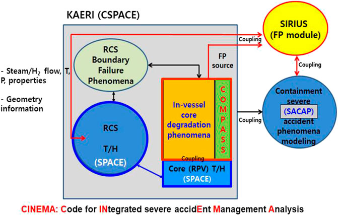
FIGURE 2. Inter link of CINEMA modules.
However, the version of the codes used in this analysis is different from those used in the analysis of APR-1400. Modifications and improvement are made for COMPASS (SMART, 2018b) and SACAP (SACAP, 2018), which are documented separately. The version of the code are identified with the size and date of the files. The detailed description of input models for CSPACE, COMPASS, SACAP, and MASTER of the CINEMA-SMART code is provided in the reference (SMART-PPE, 2018), where the Total Loss Of Feed Water (TLOFW) accident is simulated. The input deck for simulation of SBO is nearly the same as that in the reference (SMART-PPE, 2018). The only difference between these two input decks is the start of reactor trip. The transient is initiated by the reactor trip in the SBO scenario, while the transient is initiated by a loss of feed water flow in the TLOFW scenario.
Input Model for CSPACE
A node-flow path network for the modeling of SMART nuclear steam supply system is provided in Figure 3. There are two kinds of volume. First kind of volume is used for both SPACE and COMPASS and the second kind of volume is used only for SPACE. For the first kind of volume, SPACE calculates all the thermal thermal-hydraulic conditions, while COMPASS calculates the response of heat structures that COMPASS provides heat flux to and from the SPACE. COMPASS calculates the response of heat structures such as damage and melting of the core and failure of the reactor vessel.
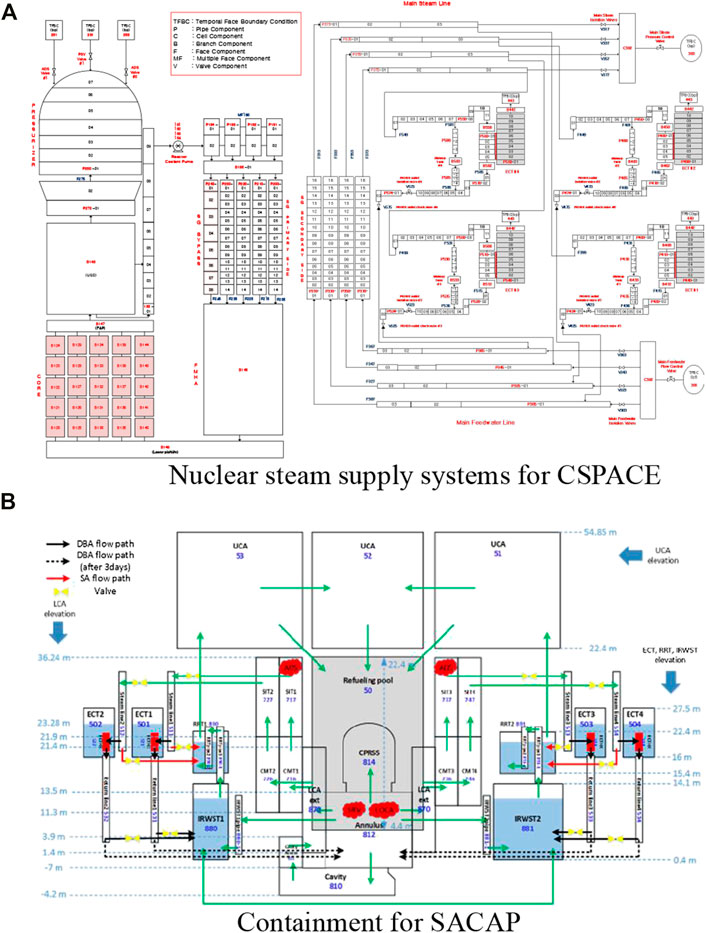
FIGURE 3. Nodalization of SMART365. (A) Nuclear steam supply systems for CSPACE. (B) Containment for SACAP.
The first modification has to be made to the input for SPACE. We need to define the SAM-Nodes, which are shared by COMPASS and SPACE. The SAM-Nodes includes 25 core nodes of B120-B144, down-comer (FMHA) B145, lower plenum B146, Fuel Alignment Plate (FAP) B147, and Upper Guide Structure (UGS) B148. They should use the keyword SAM in the input. For these nodes C-SAM-2000 card is needed for assigning the power fraction for each node. And heat structures presented in the SPACE have to be taken out because COMPASS will take care of heat structures in those nodes. Also, reference heat structure for KINE- input should be assigned to the heat structures in the SPACE node such as heat structures of the pressurizer. Finally, modifications are needed to adjust minor edits incorporating the changes made above.
Use or Removal of Safety Systems: In the SMART NSSS (Nuclear Steam Supply System) design, various safety systems such as Automatic Depressurization System (ADS), Passive Safety Injection System (PSIS), and Passive Decay Heat Removal Systems (PRHRS) are employed for mitigating the design basis accident. They can also be utilized during the progression into and during the severe accidents.
For SBO accident leading to the core damage, we had to assume that PSIS and PRHRS do not work, since the possibility of failure of the passive safety systems are very low. In the actual scenario, as those safety systems are operable, SBO event would not lead to the core damage. In this analysis, the input cards for thermal-hydraulics and heat structures for describing the operation of PSIS, PRHRS were removed from the SPACE input.
However, ADS was modeled that the operator would open the ADS 30 min after reaching the sever accident management entry condition which is defined as the time when the core exit temperature of C147-01 reach the 650°C (923.15 K). SMART has two ADS lines and the exit of ADS lines are connected to the SIT room 1 and 3. The diameter of orifices of ADS line is 35.6 mm. Based on this are, the flow area of ADS, 9.95382 × 10⁻⁴, is determined as an input for CSPACE for TFBCs of C281 and C283.
Ransom–Trap model is used for the break flow through the ADS and PSVs. This is because Henry–Fauske model option in the SPACE has an error when non-condensible gas such as hydrogen is included in the break flow. Also, internal choking was not allowed to minimize numerical instability.
Main Steam Relief valves are implemented as a part of PRHRS. Each steam line has one MSRVs that 4 valves are installed in total. The design data is shown in page 40 of the document that inlet line size is 0.75 inch, opening set point is 17MPa with 3% blowdown. These data are incorporated in the C319, C339, C359, and C379 and related input cards for actuation. MSRVs are especially necessary when PRHRS was not working properly that secondary heat removal capability was lost. Especially, during a severe accident with significant core damage hot steam coming from the core would flow through the steam generator that it would heat up and pressurize the confined secondary volume between the main steam isolation valve and main feed water isolation valve.
ANS 73 decay heat with 1.2 multiplier instead of ANS79 decay heat (Lee et al., 2014) is used to provide conservative core melt progression.
Addition to the reference case, we performed the sensitivity studies for a PRHRS and operator action time after reaching Severe Accident (SA) entry condition. Since a PRHRS is adopted as a heat sink by a natural circulation in the secondary side instead of Auxiliary Feed Water System (AFWS), the isolation valves connected with the main steam line is open when the primary pressure is below 11.3 MPa. For sensitivity of operator action time, two cases for 0 s and 3,600 s as well as 1,800 s of reference case are simulated.
Code Simulations
In-Vessel Accident Sequence
The results of steady state calculation are used as the initial conditions of the transient calculation. Table 1 shows the steady state calculation results compared with the target design values of SMART.
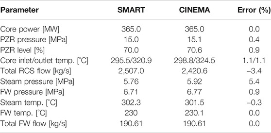
TABLE 1. Steady-state calculation results.
As long as the geometrical information and initial fluid information of the SMART reactor are well implemented in the code calculation, the target steady-state results can be recalculated by the code.
The history of major accident progression for a SBO accident is given in Table 2. The SBO occurs at 0.0 s assuming the complete loss of on-site and off-site power. The reactor trip is automatically initiated, from this moment any active system of the plant becomes unavailable in particular the Reactor Coolant Pump (RCP) and the Feed Water (FW) pumps run down. The Automatic opening and closing are repeated when the temperature of the coolant inside the Reactor Coolant System (RCS) rises and the pressure setting of Safety Relief Valves (SRVs) on the top of pressurizer is reached. The safety injection system is not available as well as the recovery of the RCP and FW pump is not performed. From a SBO analysis of a loop type PWR (Wang et al., 2012), it was shown that the availability of passive safety system can remove the core decay heat from the primary loop effectively. However, without any safety systems during a SBO in the SMART reactor, continuous loss of inventory through the pressurizer SRVs results in dry-out of the fuel rods and subsequent heat-up of the reactor core.
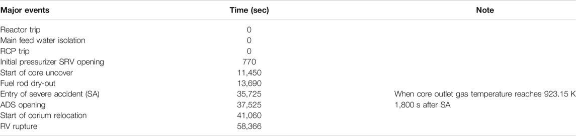
TABLE 2. Times of major events during a SBO accident.
The top of the core begins to be exposed at the time of 11,450 s and hydrogen is generated at 38,550 s from the cladding in the fuel rod zone.
The hot water vapor is released and the vapor temperature at the outlet of core is increased to 923.15 K at 35,725 s, which is the Severe Accident (SA) entry condition. It is assumed that the operator opens two out of four Automatic Discharge Valves (ADSs) 1,800 s after the SA entry condition because a portable power generator can provide only one of two electric trains. When ADS valves are opened the RCS is rapidly depressurized below to 1.7 MPa. The accident scenario progresses to core melting, corium relocation to the lower plenum and, eventually, Reactor Pressure Vessel (RPV) failure.
RCS Pressure
The pressure changes inside the RCS of the primary system is shown in Figure 4. The RCS pressure remains high (17.3 MPa, which is the pressurizer SRV opening pressure) showing a cycling trend around the valve opening set point of SRVs. However the RCS pressure is rapidly decreased and maintained to about 0.23 MPa after ADS valve opening.
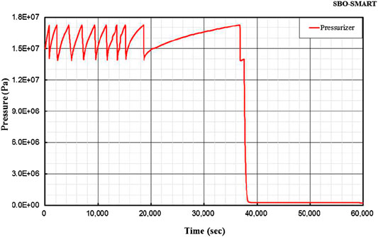
FIGURE 4. Primary RCS pressure.
High-pressure corium ejection/direct containment heating is one of the phenomena of severe accidents following the reactor vessel break. The RCS pressure is the key factor affecting this phenomenon. It is shown that the RCS pressure remains lower than 1.7 MPa since the safety depressurization by ADS valves are effective.
The critical pressure to occur Direct Containment Heating (DCH) has been known not to be lower than 2.07 MPa (300 psia) through the experimental studies on the containments of commercial LWR nuclear power plants and, in general, 1.72 MPa (250 psia) is conservatively used. It is shown that when the depressurization system is operated in a SBO sequence, RCS is depressurized up to 1.7 MPa as shown in Figure 4, therefore, DCH would not occur.
Reactor Core Level
Figure 5 shows the variation in coolant level inside the reactor pressure vessel. The reference point is the bottom of the lower head of the reactor vessel. As the loss of coolant due to automatic opening of POSRV continues, inventory of the coolant decreases smoothly. After the water level of the upper plenum is depleted the core exposure begins from the top side. The water level of the core quickly falls to the bottom of the core at 13,690 s. Note that the levels shown in Figure 5 below are based on the liquid fraction calculated from the thermal-hydraulic element at the corresponding elevation of the core.
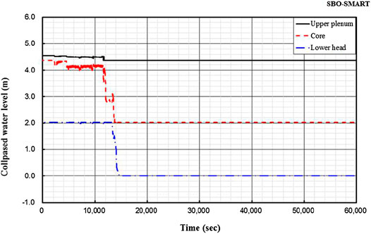
FIGURE 5. Reactor core level.
RCS Temperature
Figure 6 shows the temperature variation of the coolant in the core area and the lower head of the reactor vessel. The change of the maximum fuel temperature is also taken into account. The temperature variation of the vapor coolant follows that of the heated fuel rods and reaches the maximum, which is the fuel melting temperature (2,400 K). However the water coolant temperature maintains nearly the same but decreases after ADS opening at 37,525 s.
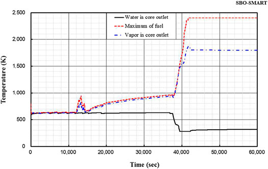
FIGURE 6. Reactor temperature.
Discharge Flow Through SRV and ADS Valves
Figure 7 shows the discharge mass flow through the SRV on the top of the pressurizer. The steam of the RCS starts to release from the point of the opening of SRVs. At the beginning of the opening, only release of vapor was found to be about 50 kg/s, followed by the release of the water inventory up to about 116 kg/s. After 7,000 s only the steam is released through the SRVs.
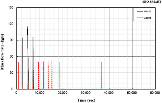
FIGURE 7. Discharge flow rate through SRV.
Figure 8 shows the discharge mass flow through the ADS valves. As the ADS valve starts to open the steam is rapidly released up to 39 kg/s. Any water inventory is not released during the ADS venting. The Ransom–Trapp model is used for the choking option of the SRVs.
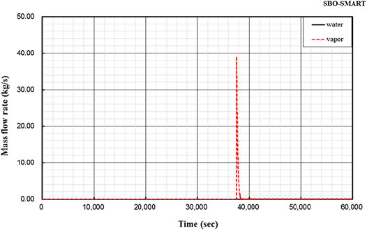
FIGURE 8. Discharge flow rate through ADS valve.
Hydrogen Generation Rate
The fuel cladding temperature rapidly increases with core uncovery when the level in the reactor vessel falls below the active core, and it leads to the oxidation reaction of the clad metal with steam to generate hydrogen.
The hydrogen generation rate inside the reactor vessel is shown in Figure 9. The hydrogen generation characteristics due to cladding oxidation depend heavily on the hot cladding-steam contact area characteristics and the depletion of water vapor that are determined by the degree to which the core structure is destroyed. It is also greatly affected by the physical-chemical interaction caused by the mixing of multiple metals and oxide metals at very high temperatures. This information is highly dependent on approach of the core modeling and the thermal-hydraulic modeling between severe accident analysis codes.
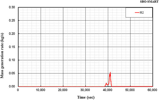
FIGURE 9. Discharge flow rate of H2 through ADS valve.
The predicted hydrogen production rate from core melt in this SBO accident analysis is predicted to be up to about 0.05 kg/s.
Figure 10 shows the cumulative hydrogen mass produced in the reactor vessel, and the total mass of hydrogen generation is about 49 kg.
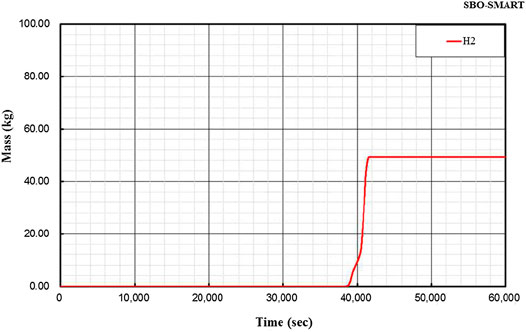
FIGURE 10. Hydrogen mass.
Lower Head Wall Temperature
Figure 11 shows the temperature of the inner wall of the reactor vessel lower head. In this calculation, the wall temperature shown in this figure is the average surface temperature over the lower head, since a model is considered to be a single node with uniform properties. It is judged that the average temperature of the lower head is increased smoothly until the start of relocation. After the relocation to the lower head, the wall temperature begins to rise rapidly, and about 17,500 s after the relocation, the wall temperature reached the melting temperature of the material and the reactor vessel was expected to break.
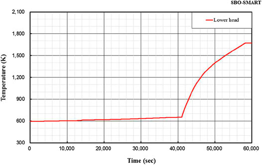
FIGURE 11. Lower head temperature.
Cladding Temperature
In this analysis, the effective core region by the COMPASS module input is modeled by dividing the effective core section into five rings and five nodes in the radial and axial direction, respectively. Of these, the cladding surface temperature according to the axial position in the central ring is shown in Figure 12. The first factor determining the cladding temperature is the exposure of the corresponding node at each elevation. As shown in Figure 12 the cladding temperatures increase from the start of core uncovery and rapidly increase after opening of ADS valves, since the rapid discharge of core inventory through the ADS valves enhances the core heat up.
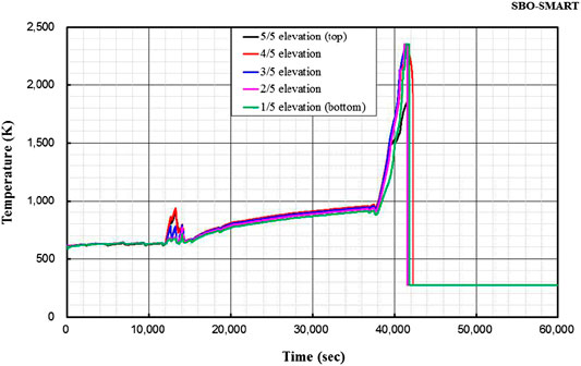
FIGURE 12. Cladding temperature.
The cladding temperatures start to rise with a difference of time after exposure of the core nodes lower than the upper core plenum. The cladding temperatures reach the maximum value corresponding to the melting temperature and decreased to 0 K when the fuel material in the node is relocated and there is no more mass left.
Fuel Temperature
The fuel temperatures at each axial nodes in the core of the central ring are shown in Figure 13. The trend of temperature variation for fuel rods is similar to that of cladding material. The temperature is expressed to be 0 K when the fuel material in the node is relocated and there is no more mass left. The maximum temperature corresponding to the fuel melting temperature is 2400 K.
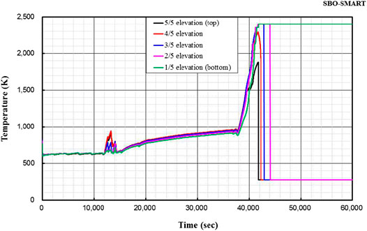
FIGURE 13. Fuel temperature.
Mass of Corium in Lower Head
Figure 14 shows the variation of corium mass in the lower head of the reactor vessel. At the time of initial relocation, only about 8,767 kg of metal corium is relocated, and after that, the oxide corium starts to be relocated. This is because the melting temperature of the metal corium is lower than that of the oxide corium.
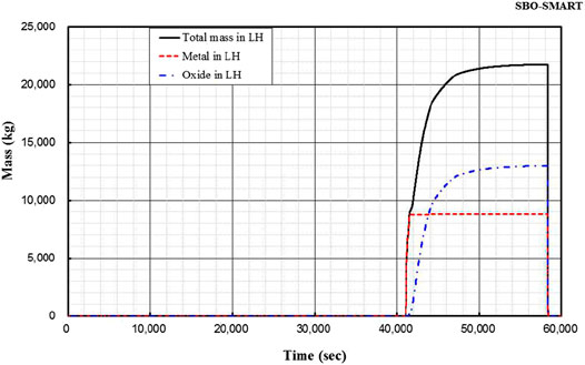
FIGURE 14. Corium mass.
The oxidation corium is continuously relocated following accident progress, and at the time of the reactor vessel damage, it is expected that the oxidation corium eventually increases to about 12,980 kg resulting in a total of approximately 21,750 kg. Since the melting pool in the lower head is modeled to a single volume, it is possible to verify that all of the melting corium in the lower head is released immediately upon failure of the reactor vessel. At the time of initial relocation, only metallic materials such as Zr, SS and Inconel of which melting temperature is relatively low are melted and relocated to the lower head. And then, the oxide corium such as UO2 is relocated to the lower head.
Sensitivity Studies
Operator Action Time After Severe Accident Conditions
Three cases for different opening time for ADS valves after SA condition are simulated and the maximum fuel temperatures for each case are compared in Figure 15. As the operator action time to open ADS valves is increased, the heat up of fuel temperature showing the progress of severe accident is also delayed. However, the assumption of 30 min (1,800 s) for reference case is not much different from more delayed case of 3,600 s.
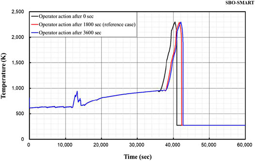
FIGURE 15. Comparison of fuel temperatures for different operator action times.
PRHRS Operation
The fuel temperature behaviors with and without PRHRS are compared in Figure 16. After the core exposure begins around 1,300 s (see Figure 5) the fuel temperature shows the peak value. When the PRHRS is actuated to remove the decay heat in the secondary side, the peak fuel temperature becomes lower than the reference case without PRHRS.
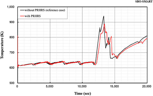
FIGURE 16. Effect of PRHRS operation on the peak fuel temperature before severe accident.
Ex-Vessel Accident Progression
Containment Pressure
Figure 17 shows the pressure variation in the Upper Containment Area (UCA) of the reactor building. The containment pressure increases as the high pressure of RCS is discharged into the containment by opening and closing of the pressurizer SRV after the accident. After about 20,000 s, the pressure remains nearly constant as about 117 kPa and suddenly increased up to 120 kPa when ADS valves are open. The accident sequence shows the maximum pressure at the time of reactor vessel damage is 119 kPa.
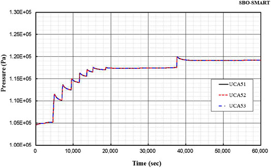
FIGURE 17. Containment pressure in the UCA.
After the RCS inventory is released through the reactor vessel break, it shows a momentary rise due to the inflow of corium discharged through the reactor vessel break.
The total number of PARs (Passive Auto-catalytic Re-combiners) and those locations are determined based on the assessment on the hydrogen distributions over the compartments of Low Containment Area (LCA) and UCA during the representative severe accident progression.
The containment pressure decreases gradually since the PAR is successfully actuated. It is shown that the containment integrity is not threatened by the high containment pressure.
Containment Temperature
Figure 18 shows the containment temperature in the UCA of the reactor building. The containment temperature follows a similar trend to the containment pressure. However, there is no sudden temperature increase following the reactor vessel break, and the temperature remains below 400 K with a maximum temperature of 321 K throughout the analysis period.
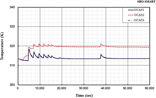
FIGURE 18. Containment temperature in the UCA.
Conclusion
A SBO analysis was performed by CINEMA code that the transient scenario inside the reactor vessel after an initiating event, core heating and melting by core uncovery, relocation of debris, reactor vessel failure, discharge of molten core, and pressurization of the containment were simulated.
When the core is fully molten and most of the core materials relocate to the lower head, the integrity of the reactor vessel is maintained by the External Reactor Vessel Cooling (ERVC) via the coolant surrounding the reactor vessel which is supplied from IRWST after opening the valve of the Cavity Flooding System (CFS). Depressurization of the containment area is done by mainly venting to RRT (Radioactive material Removal Tank) during the severe accident condition. The design such as containment cooling system of the ACSS (Ancillary Containment Spray System) is considered as a supplementary system for overpressure protection for the extended period.
SMART containment area has very large volume and has open-type internal structure so that hydrogen is mixed well and hydrogen concentration is maintained uniformly at low level. Also, the containment area is designed firmly enough to withstand hydrogen combustion. The accumulated amount of the hydrogen during the severe accident can be reliably controlled by PARs. The containment analysis results are as follows.
• Hydrogen mixing in the containment area is assured.
• It is shown that the uniform hydrogen concentration in the containment area is less than 10% in volume when the hydrogen mitigation system is operated.
• When hydrogen is generated by the reaction between 100% of fuel clad metal and water, the containment integrity is maintained if the hydrogen mitigation system is operated.
Finally, it is shown that the integrity of the containment can be maintained during a SBO accident in the SMART reactor. It has to be mentioned that the assumptions used in this analysis are extremely conservative that the passive safety systems of Passive Safety Injection System (PSIS) and Passive Residual Heat Removal System (PRHRS) were not credited. In addition, as ANS73 decay heat with 1.2 multiplier was used in this analysis, actual progression of the accident would be much slow and amount of hydrogen generation will be much less.
Data Availability Statement
All datasets generated for this study are included in the article/Supplementary Material.
Author Contributions
All authors have made a substantial, direct, and intellectual contribution to the work and approved it for publication.
Funding
This work was supported by the National Research Foundation of Korea (NRF) grant funded by the Korea government (Ministry of Science, ICT, and Future Planning) (No. 2012M2A8A4025889).
Conflict of Interest
The authors declare that the research was conducted in the absence of any commercial or financial relationships that could be construed as a potential conflict of interest.
Abbreviations
AC, alternate current; ACSS, ancillary containment spray system; ADS, automatic depressurization system; AFWS, Auxiliary Feed Water System; CFS, cavity flooding system; CINEMA-SMART, Code for INtegrated severe accidEnt Management and Analysis-SMART; DCH, direct containment heating; DL2, Design Level 2; ECT, emergency cool down tank; CT, compensating tank; EDGs, emergency diesel generators; ERVC, external reactor vessel cooling; FAP, fuel alignment plate; FW, feed water; KAERI, Korea atomic energy research institute; LCA, lower containment area; LWR, light water reactor; MPI, message passing interface; NSSS, nuclear steam supply system; PAR, passive auto-catalytic re-combiner; PRHRS, passive decay heat removal systems; PSIS, passive safety injection system; RCP, reactor coolant pump; RCS, reactor coolant system; RPV, reactor pressure vessel; RRT, radioactive material removal tank; SA, severe accident; SBO, station blackout; SMART, system-integrated modular advanced reactor; SRVs, safety relief valves; TLOFW, total loss of feed water; UCA, upper containment area; UGS, upper guide structure
References
IAEA (2005). Innovative small and medium sized reactors: design features, safety approaches and R&D trends. Vienna, Austria: IAEA-TECDOC 1451IAEA.
KAERI (2017). Development of severe accident containment analysis module, June. S11NJ16-2-F-PR-5.10.5.
Kim, D. H., Song, J. H., Lee, B. C., Na, J. H., and Kim, H. T. (2017). “Development of an Integrated severe accident analysis computer program packages in Korea” in Proceedings of the 8th European review meeting on severe accident research (ERMSAR-2017). Warsaw, Poland.
Kim, K. K., Lee, W., Choi, S., Kim, H. R., and Ha, J. (2014). SMART: the first licensed advanced integral reactor. J. Energy Power Eng. 8, 94–102.
Lee, D. H. (2018). Development of SPACE Input for severe accident analysis of SMART 365 MWth(DL2), Rev. 00. KAERI/CM-264/2018, Technical Report. Republic of Korea:KAERI.
Lee, S. W., Chung, B. D., Bang, Y-S., and Bae, S. W. (2014). Analysis of Uncertainty quantification method by comparing Monte–Carlo method and Wilk’s formula. Nucl. Energy Technol. 46, 481–468. doi:10.1021/es302971d
SMART (2018a). COMPASS Code Input Calculation for severe accident analysis in SMART. KAERI/TR-7495/2018.
Keywords: SBO (station black out) accident, SMART reactor, CINEMA code, reactor safety, severe accident analysis
Citation: Kim HT, Song JH and Park R-J (2020) Simulation of a Station Blackout Accident for the SMART Using the CINEMA Code. Front. Energy Res. 8:503918. doi: 10.3389/fenrg.2020.503918
Received: 10 October 2019; Accepted: 24 November 2020;
Published: 21 December 2020.
Edited by:
Arun Kumar Nayak, Bhabha Atomic Research Centre (BARC), IndiaReviewed by:
Mingjun Wang, Xi'an Jiaotong University, ChinaIvo Kljenak, Institut Jožef Stefan (IJS), Slovenia
Liangming Pan, Chongqing University, China
Copyright © 2020 Kim, Song and Park. This is an open-access article distributed under the terms of the Creative Commons Attribution License (CC BY). The use, distribution or reproduction in other forums is permitted, provided the original author(s) and the copyright owner(s) are credited and that the original publication in this journal is cited, in accordance with accepted academic practice. No use, distribution or reproduction is permitted which does not comply with these terms.
*Correspondence: Hyoung Tae Kim, a2h0QGthZXJpLnJlLmty