 Dristi Datta1
 Shahriar Rahman Fahim2
 Subrata K. Sarker1*
 S. M. Muyeen3Md. Rafiqul Islam Sheikh2
 Sajal K. Das4
- 1Department of Electrical and Electronic Engineering, Varendra University, Rajshahi, Bangladesh
- 2Department of Electrical and Electronic Engineering, Rajshahi University of Engineering and Technology, Rajshahi, Bangladesh
- 3School of Electrical Engineering, Computing and Mathematical Sciences, Curtin University, Perth, Australia
- 4Department of Mechatronics Engineering, Rajshahi University of Engineering and Technology, Rajshahi, Bangladesh
Future microgrids (MGs) will comprise of an enormous number of little secondary networks (SN) that will convey complex control for grid collaboration as well as tracking of operation. In this paper, a robust blended integral linear-quadratic-Gaussian (ILQG) controller is proposed for damping and tracking control of SN voltage of a PV based hybrid source of AC-DC microgrid against a number of operating conditions. The structure of this mixed controller is made by expanding the SN dynamics with the utilization of an integrator. The term SN signifies a network that can take power from the DC bus connected with the AC main grid and PV based DC grid. The aim of developing a DC bus is to provide the constant DC voltage in the SN load terminal which is made of a parallel combination of several uncertain and unknown loads that may produce the oscillation of its performance. The proposed blended integral linear-quadratic-Gaussian controller provides a large control bandwidth that not only reduces the oscillation but also confirms the improved tracking performance over the number of loads in SN premises. Additionally, several uncertainties are considered within the SN dynamics to check the robustness of the proposed blended controller. The evaluation of this blended controller is studied for the various load dynamics and compared with the linear-quadratic Gaussian (LQG), linear-quadratic-regulator (LQR), and integral controller (IC) in terms of settling time, bandwidth and tracking performances.
Introduction
Microgrid (MG) is considered as an alternative way to provide un-interrupted power to the end-user when it is apart from the main AC grid (Malik et al., 2017). In modern electrical network, it is widely used because of its ability to run independently (Bouzid et al., 2015). A typical MG consists of energy storage (ES) elements (e.g., flywheel, battery, etc.), heterogeneously combined with a number of distributed generation (DG) units, point of common-coupling, loads and renewable power sources (RPS) (Xia et al., 2017). The idea of MG has become increasingly popular as it demands low cost in case of power generation from RPS, enhances local reliability, compensates feeder losses, and provides voltage support/voltage sag correction (Badal et al., 2019; Armin et al., 2020; Rizi and Eliasi, 2020). Several types of MG like AC MG, DC MG and hybrid source of AC/DC MG can be found in power system (Sarkar et al., 2018b; Toghani Holari et al., 2020). Among them, the hybrid source of AC/DC MG with energy technologies are brought up new opportunities for the use of renewable energy sources as it can operate in both cases.
The hybrid source of AC-DC MG may compose of a DC source like solar panel/energy storage unit, AC source like wind, diesel generator/main AC grid and controllable AC/DC loads. The combination of these sources are done with a single bus system that offers reliable, stable, and secure energy for the end-user (Jayachandran and Ravi, 2017; Lotfi and Khodaei, 2017; Liang et al., 2019). The DG units and AC/DC loads can be accessed from the DC bus through the use of the power electronic converter. A grid-tried inverter, which converts the DC power into AC power, is mainly used as a bridge between the AC and DC source so as the power can be easily exchanged according to the end-user demand (Llaria et al., 2011; Kim et al., 2012). Besides, the DC source can provide an immediate backup power response dynamically to meet the exceeding power demand. The main role of this type of MG is to generate power using the green energy and supply it to the end-user through the low amount emission of the greenhouse gas that keeps the environment clean and increases the overall efficiency of the transmitting power (Infield and Freris, 2020).
Figure 1 represents a typical hybrid source of AC-DC MG system mostly used in the real-time environment consisting of a secondary network, AC main grid, and PV based power generation unit. The function of the PV unit is to generate DC power and supply it into the secondary networks (SN) premises with the use of an inverter, where the AC main grid provides power when the PV unit can not meet the user demand power due to the environmental conditions. The interaction among the main AC and DC grid makes a way to maintain the constant power source for the SN. This is necessary as the generation of power using a PV panel may vary due to the unpredictable nature of the solar strength. This unpredictable nature produces the oscillation in MG system operation.
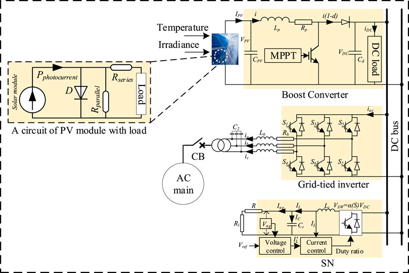
FIGURE 1. A basic circuit diagram of the proposed hybrid source of AC-DC MG system.
The operation of an hybrid source of MG fundamentally relies on the connection between the principle AC and the DC framework that may fail due to the unknown disturbances (Carpinelli et al., 2017; Salman and Xin, 2020). Accordingly, the performance of the SN may degrade causes the variable nature of sustainable energy sources which act as the prime mover for the operation of SN. The solar strength, irradiance, wind speed, and others are the main key factors to drive the performance of these prime movers. The variation of these factors may create a large number of oscillations that are responsible to reduce the tracking operation of the SN (Bouzid et al., 2015). Additionally, the variation of load dynamics in the SN system can alter the system dynamics that can also create the un-damped resonance during its operation.
A few control methods have been already reported for enhancing the voltage quality of the SN (Sikder et al., 2018a; Sikder et al., 2018b; Armin et al., 2018). Proportional-integral-derivative (PID) controller is developed for tracking the voltage due to its simplicity (Sarkar et al., 2018a). The controller is designed by assuming the constant input DC source. Although this controller can provide improved tracking performance over the constant source, the variation of PV parameters can alter the input DC source that may reason to confirm the lower tracking performance of the PID controller. An LQR is considered to regulate the MG voltage (Das et al., 2016; Levine, 2018). This controller achieves high performance against the RLC network connected in a parallel manner with the MGs. However, the absence of robustness with the adjustment in the plant dynamics restricts the utilization of the LQR. An H
Model Predictive Controller (MPC) has also been considered with the aim of providing robustness in terms of plant dynamics change (Lou et al., 2017). However, the response speed of the MPCs is limited due to their low-bandwidth. Distributed adaptive control techniques perform independently to control the voltage of the MG using remote sensing methods (Bidram et al., 2014; Kammer and Karimi, 2017). The communication speed with the correspondence load framework constrains the utilization of this control. Three levels of hierarchical control strategy have been considered to relieve from the tracking deviation and optimize the economic dispatch over the entire MG system (Mohamed and Radwan, 2011; Simpson-Porco et al., 2015). When one of the levels of this control fails, it departs from the tracking accuracy level.
To obatin the tracking voltage for the operation of the MG, the structure of a servo controller is introduced (Karimi et al., 2010). The design of this controller follows linear-time-invariant (LTI) theory (Sadabadi et al., 2017). The performance of this controller strays from the ideal result in the case of nonlinear load. A hybrid controller, which combines a proportional-integral (PI) controller and a harmonic resonant controller, has been considered to obtain the zero steady-state error and tracking performance over the various loads (Shen et al., 2010). In high resonant frequencies, this controller performs as a low pass controller and produces a lower gain and phase margin. The lower control margin shortens the application of this controller over the uncertainties.
Motivated by previously mentioned issues, in this research, we propose a robust blended integral linear-quadratic-Gaussian (ILQG) control framework for improving the load voltage profile of a solar-powered MG system consisting of AC and DC sources with a secondary network. The inspiration for planning this strategy is its capacity to follow the reference sign and exhibit the robustness over the plant vulnerability/uncertainty. This research aim is to control and secure the fast robust balancing of the secondary network voltage mismatch for the variation of linear and nonlinear load dynamics and the variation of temperature and irradiance of the PV system.
The contributions of this paper are as per the following:
• Design a robust high-performance controller by expanding the SN plant elements with an integrator which decreases the voltage swaying by increasing the control bandwidth that results in offering high phase and gain margin. The increasing control margin confirms the improved tracking performance for the SN.
• Develop a reliable DC bus using the conventional PI controller that provides a controlled constant DC voltage for the secondary network over the variation of temperature and irradiance.
• Several load dynamics are considered into the SN premises and simulated to measure the tracking capability of the controller.
• Various uncertainties are considered to affirm the robust performance of the ILQG framework.
• Performance comparison between the ILQG, linear-quadratic Gaussian (LQG), and LQR is done over the various load dynamics to ensure the high tracking performance of the proposed controller.
The remainder of this paper is sorted out as follows: Section 2 describes the details design of the solar-powered based hybrid AC-DC MGs with modelling of the secondary network. The modelling of the blended ILQG control structure for the voltage control of an SN is completed in Section 3. Section 4 arrangements with the presentation assessment of the ILQG controller for the voltage control of SN. The paper is finished up in Section 5.
System Configuration and Modeling
Hybrid Microgrid Configuration
The concept of a hybrid source of MG induces for improving the operation of the renewable energy resources having with a main AC grid systems and loads. Figure 1 shows a compact representation of the MGs carrying with a PV source and load which is connected with the corresponding AC and DC networks through a three-phase grid-tried inveter. An SN is connected with the corresponding DC bus through a voltage source inverter (VSI) and filter. The switching voltage from the voltage source inverter is used to drive the loads connected with the secondary networks.
An MG can drive the power in both grids and islanded connected mode. In grid-connected, a three-phase grid-tried inverter is required to provide the stable DC bus voltage. The role of this converter is to exchange power from the primary AC network to the DC bus or vice-versa. The solar PV array acts as an energy source that is associated with the DC bus by a DC/DC boost converter. This converter aims to extract the extreme power from the PV framework and track it using an artificial neural network. When the output from the PV system is greater than the total power consumed at the DC bus, the three-phase converter infuses power to the essential primary AC network while going about as an inverter. On the other hand, if the generation of total power at the DC bus is less than the required power, the converter infuses power to the DC network.
In the case of the secondary network operation, the harmonics may produce during the switching action from the DC to AC voltage. An inductive load is used to attenuate the harmonics and keep up the stability of the exchanging mode voltage. The use of inductive load may demand more current from the DC bus. As a result, an additional capacitor is used to cover the peak demand current without causing the need for an extra converter in input voltage. The combination of an inductor and capacitor acts as a filter for the SN that not only keeps the constant voltage but also increase the injected power to the load.
A voltage control method for the SN carrying with an inverter is also depicted in Figure 1. This method carries two control loop; outer and inner control loop that provides the required duty ratio for the switching performance of the inverter. The inner control loop is considered to produce the duty ratio, whereas the outer control loop uses the controlled duty ratio for tracking the SN voltage. The generation of the duty ratio is done by comparing a triangular carrier signal and a sinusoidal reference signal. The comparison between the two signals produces the required pulses when the peak of the reference signal is lower than the amplitude of the carrier signal. These pulses are considered to perform the switching action of the inverter. The deviation of the switching signal is measured by using the modulation index which provides the desired duty ratio. The proper duty ratio allows the controller to achieve the large bandwidth that provides high tracking performance for the SN over the un-modeled loads and uncertainties.
Modeling of PV Source
The PV arrays consist of several P-N junction diodes that can produce electricity from the insulation of solar radiation. The simple and mostly used model to represent the solar cell is a single diode circuit model reported in Figure 1 carrying of a PV and a diode with series-parallel resistance. The function of the diode is to identify the nature of the I-V and P-V characteristic curves. In practically, the output of the diode may degrade the perception level of the P-V or I-V curve due to the poor design or manufacturing defects. A shunt diode resistance is connected in parallel with a diode that enables a bypass way to generate the current. The output current from the PV module in Figure 1 is represented as:
The notations and designed parameters value of the PV system are presented in Table 1. These values are determined by using the criteria of the real PV system so that the studied PV system can meet all the conditions to work in a real-time environment.
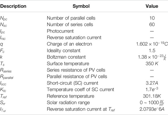
TABLE 1. Model parameter for PV module.
Control Modeling of Secondary Network
Let IL be the current passing through the SN inductor as:
where V
Where Ic represents the capacitor current. Now the state-space representation of proposed system with disturbance can be written as:
and the system output equation is:
Here,
Control of Hybrid Microgrid
Coordination Control for Booster and Bidirectional Converter
A control block diagram is shown in Figure 2A to maintain the steady operation among the main AC and DC grid under variable load demand and supply condition. The development of the MPPT algorithm is needed to identify the maximmum power (MP) from the solar PV module under variable temperature and shading conditions. The variation of these parameter creates the variation of the DC-link voltage used for the control of MP point as shown in Figure 3A. In this paper, the ANN is chosen to determine the reference voltage
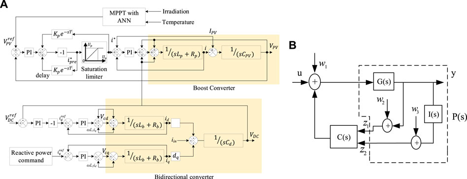
FIGURE 2. Block diagram of (A) DC bus voltage stabilizer using conventional PI regulator and (B) proposed integral linear-quadratic-Gaussian (ILQG) controller.
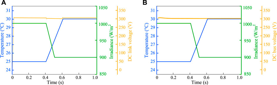
FIGURE 3. (A) DC-link voltage used for the control of MPPT, (B) Stable DC bus voltage over the variation of temperature and irradiance.
A dual-loop control scheme is considered to track the reference voltage
Likewise, during the power shortage at the DC bus, the grid-tried inverter injects power from the main AC grid to the DC grid. The lack of DC bus power produces a positive error of
Proposed Voltage Control for Secondary Network
This section explores the design of blended controller for SN voltage control of a hybrid source of MGs. The proposed controller carries the combination of an integral controller (IC) and a LQG controller. The goal of designing this controller is to address the challenges made during the design of LQG and IC, respectively.
Design of Proposed Controller
Consider the following state-space model of the plant:
where x speaks to the state vector, the term u signifies the contribution for the framework, y is the deliberate output from the ideal plant, and w is a Gaussian repetitive disturbance following up on the framework; A, B, and C represent the system matrix, input matrix, output matrix, and D
The design of an optimal LQG controller starts with a model in the form (Eq. 3)–((Eq. 4). Here, the quantity w(t) describes the process noise and
Here, Q
It should be noted that the design of the LQG controller does not directly address the robustness issues against the plant uncertainty. The robustness of the LQG controller is tended to by the reasonable decision of the noise terms in the plant model (Eq. 3)–(Eq. 4) that reflects the desired bandwidth and robustness characteristics. The control objective in this article is to minimize the tracking error among the command signal and the measured output. To make this, an IC is associated with an SN system because of its its phenomenal low-frequency tracking execution. Although the high gain of the IC reduces tracking errors, it shows lower bandwidth that confirms the lack of robustness.
Motivated by the above practical limitations, we have proposed an integral LQG controller for improving the tracking performance of SN. The integral action in proposed controller is presented by adding an additional term in the cost function (Eq. 5). The additional term involves the integral of the output y. The block diagram of the proposed ILQG controller is shown in Figure 2B, where G(s) is the transfer function of the plant,
Here,
In (Eq. 6)–(Eq. 7), the quantity w
(1) The increase of
(2) The decrease of
(3) The amount of the integral action depends on the size of the
(4) The choosing a small value for r defines a control strategy with high gain system that results in provides robust performance over the uncertainties. On the other hand, selecting a large value for q defines the stable system with the least possible changes in the system states.
For the augmented plant outlined in (Eq. 6)–((Eq. 7), the integral LQG controller is designed by defining a quadratic cost function of the form
where
Here,
where P
Here, the factor Q
where
where P
Here, RC=r Is the Controller Weighting Matrix and
The controller design parameters

TABLE 2. Proposed controller parameters.
Performance Evaluation
Formulation of the Simulated System
This section discusses the tracking and damping ability of the proposed controller for the operation of the SN. A framework of the solar-powered MG system consisting of AC and DC sources with a SN is considered and simulated to measure the ability of the proposed controller where the controller is applied to damp and control the load voltage of the SN. The implementation of the proposed controller for the SN carrying with the DC-AC inverter is reported in Figure 1 where the controller controls the action of the DC-AC inverter to obtain the tracking performance over the variation of loads. The studied system is designed with a PV source which is interlinked with the primary AC grid through the DC bus. The variation of the PV parameters like temperature and irradiance confirm the variation of the DC-link voltage used for MPPT control as shown in Figure 3A that may reason to imbalance the DC bus voltage. The DC bus is maintained through the use of grid-tried inverter controlled by the conventional proportion-integral (PI) controller which provides a constant source of input voltage for the SN over the variation of temperature and irradiance as shown in Figure 3B.
The operation of the SN where the controller is applied to the DC-AC inverter may experience with the various load dynamics that may alter the SN dynamics and add the number of uncertainties which confirms the poor tracking performance without the controller. The controller is implemented to secure the fast robust balancing of the SN voltage mismatch and ensure the improved tracking performance by controlling the inverter. This event is simulated for the variation of linear and nonlinear load dynamics on the MATLAB environment and the results are compared with other control strategies. The performance of the controller is assessed with the three major studies for SN; 1) Damping performance of the proposed controller, 2) Robust performance of the proposed controller, and 3) Tracking performance of the proposed controller against various load dynamics. The detailed assessment of these studies is discussed in the following section.
Damping Performance of the Proposed Controller
The performance of the SN over the various loads may produce a large amount of voltage oscillation as the variation of loads change the system states. The open-loop time and frequency-domain response over the consumer load is reported in Figure 4. From this result, it is confirmed that the system continuously leads the oscillation in its time-domain performance while the frequency response making the damping of its peak resonance upto 150 dB. To ensure the steady-state and transient response, a high gain controller is required to operate with the open-loop system that will lead to a better reduction of oscillation. The integral action having with the proposed controller makes sure the high gain in its performance that enables the controller to provide high damping performance for the closed-loop system. The closed-loop performance using the proposed control framework is delineated in Figure 4. The closed-loop behavior of the system shows that the controller contributes to set the system state quickly by significantly reducing the oscillation. Accordingly, the outcomes from the frequency plot indicating that the peak of the resonance frequency can be set smoothly and practically close to 0 dB line. This performance confirms the high damping capability of the proposed controller.
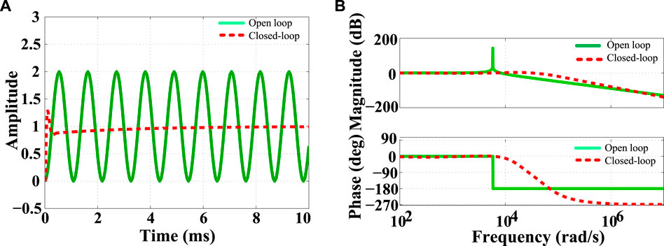
FIGURE 4. Comparison of open-loop and closed-loop for secondary networks (SN): (A) Time-domain response; (B) Frequency-domain response.
Robust Performance of the Proposed Controller
The robustness of the proposed controller is studied by adding a number of uncertainties with the plant model shown in Figure 5. Here,
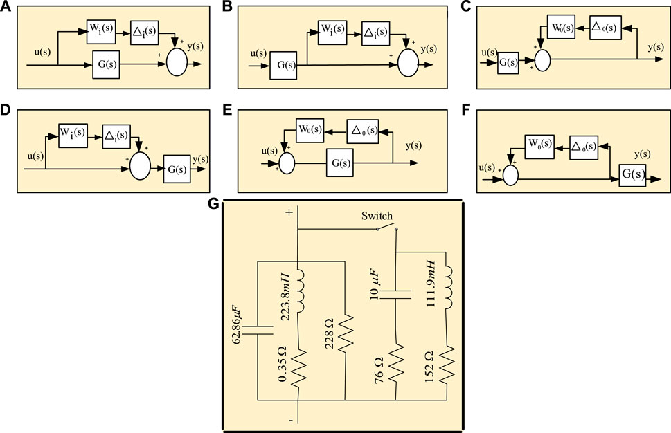
FIGURE 5. (A) Additive uncertainty; (B) Additive output uncertainty; (C) Augmentative output inverse uncertainty, (D) Augmentative input uncertainty; (E) Additive inverse uncertainty, (F) Inverse augmentative input uncertainty; (G) Inclusion of unknown passive load to the SN system.
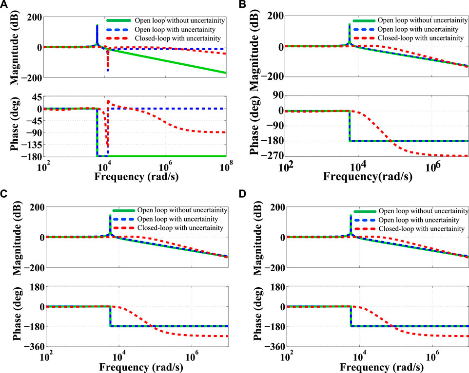
FIGURE 6. Comparison of Bode diagram using open and closed-loop: (A) for Figure 5A; (B) for Figures 5B,C; (C) for Figure 5D; (D) for Figures 5E,F.
Again, the time-domain performances for the same uncertainties are reported in Figure 7. It is observed that the open-loop behavior of the plant continuously makes more oscillation in the presence of uncertainties, while the closed-loop system takes a certain time to reduce the oscillation and reach its steady-state condition. The quantitative measurements from the frequency- and time-domain performances are given in Table 3. From these measurements, it is seen that the controller achieves high-bandwidth and takes a little time to set the system state that not only confirms the stable performance but also guarantees the robustness of the proposed controller in the presence of uncertainty. The robustness of the proposed controller is further examined by varying the system capacitor value. The variation of this value creates wide-band un-damped resonance frequency that may reason to creat the system instability. To show the effectiveness of the controller, a comparison between the open- and closed-loop performance is illustrated in Figure 8. It shows the closed-loop system can provide the same level of damping under the variation of capacitor value. Finally, it is concluded that the proposed controller guarantees the robustly stable performance for all cases.
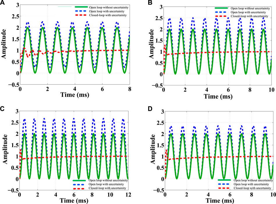
FIGURE 7. Comparison of step responses using open and closed-loop: (A) for Figure 5A; (B) for Figures 5B,C; (C) for Figure 5D; (D) for Figures 5E,F.
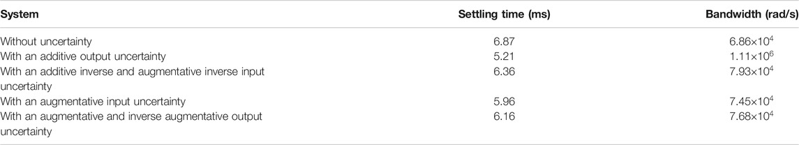
TABLE 3. Closed-loop steady state time and bandwidth with and without uncertainty.
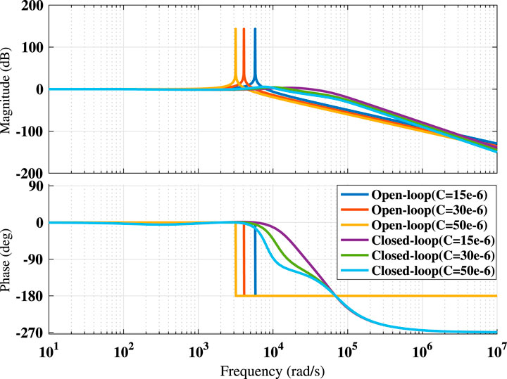
FIGURE 8. Comparison of open and closed-loop Bode diagram for various capacitor value.
Tracking Performance of the Proposed Controller Against Various Load Dynamics
Firstly, a consumer load with a value of
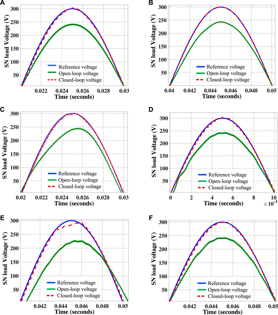
FIGURE 9. Comparison of open-loop, closed-loop and reference SN voltage tracking under (A) Consumer load; (B) Unknown load; and (C) Harmonic load; (D) Nonlinear load; (E) Asynchronous machine load; and (F) Dynamic load.
In electric networks, computers, television, fluorescent lamps, and rectifiers are used as a non-linear load. The effect of these non-linear loads produces harmonics that lead to voltage distortion in the power system. This distortion reduces the long life-sustaining of electrical loads. To produce the third harmonics in the current waveform, resistance with the value of
Further, the performance of the blended ILQG controller is studied by adding a nonlinear load in SN premises. A nonlinear load is composed of a four-pulse diode unit which is feeding with a value of
Comparative Study With Existing Controller
A comparative study between ILQG, LQG, LQR, and IC is discussed in this section. The design of the LQG, LQR and IC is done based on (Skogestad and Postlethwaite, 2007; Das et al., 2016) and (Janert, 2013), respectively. Figure 10A and Figure 10C presents the comparison of closed-loop frequency and time responses, while in Figure 10B presents the loop gains using different controllers. The results from the comparison are presented in Table 4 and Table 5. The comparison shows that the proposed controller achieves a bandwidth of 6.86
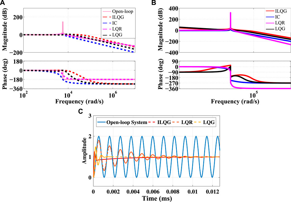
FIGURE 10. Comparative performance between (A) proposed controller, linear-quadratic Gaussian (LQG), LQR and Integral controller (IC) for Closed-loop Bode diagram, (B) proposed controller, LQG, LQR, and IC for Bode diagram of the loop-gain
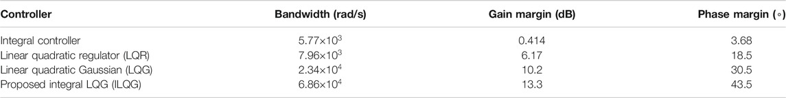
TABLE 4. Comparison of bandwidth, gain margin and phase margin using different controllers.

TABLE 5. Error voltages (RMS value) between desired and actual load voltages comparison with settling time and overshoot.
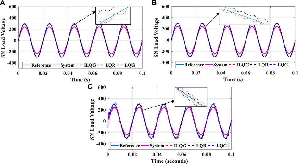
FIGURE 11. Secondary grid voltage tracking using (A) Consumer load; (B) Nonlinear load; and (C) Harmonic load model for subgrid system.
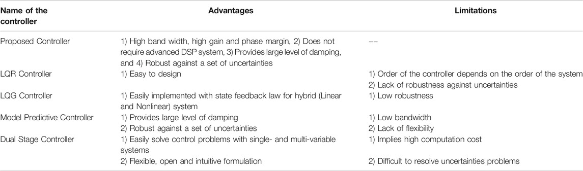
TABLE 6. Comparisons of merits between the proposed and others controller.
Conclusion
In this paper, the design of an ILQG is presented to damp the oscillation and track the secondary network voltage of a hybrid source of AC-DC MGs. The controller carries the combination of an integral and an LQG controller that able to address the low bandwidth and lack of robustness. The design of the controller is done by augmenting the SN output with an integrator. The integral action of the controller confirms the high gain which provides large bandwidth and robust performance against a number of uncertainties. Furthermore, a comparison between the proposed, LQG, LQR, and IC is presented to confirm the high effectiveness of the proposed controller. The comparative analysis is done in terms of stability parameters like bandwidth, phase and gain margin, settling time, percentage of OS, and load voltage tracking. The comparison results depicted in this paper show that the proposed controller has the ability to provide high bandwidth as well as to achieve excellence tracking performance over the variation of load dynamics as compared to others. This work should be extended for an aromatic complex power system network where several renewable sources like Biogas, PV, and wind turbine would be used to generate power.
Data Availiability Statement
The original contributions presented in the study are included in the article, further inquiries can be directed to the corresponding author/s.
Author Contributions
DD, SF, and SS developed the microgrid model, designed and evaluated the performance of the controller. SD and MRIS developed the theoretical concept of the model and proposed it for the microgrid. SS wrote the manuscript. SM reviewed and edited the manuscript. All authors read and agreed to submit this manuscript.
Conflict of Interest
The authors declare that the research was conducted in the absence of any commercial or financial relationships that could be construed as a potential conflict of interest.
References
Armin, M., Rahman, M., Rahman, M. M., Sarker, S. K., Das, S. K., Islam, M. R., et al. (2020). Robust extended H∞ control strategy using linear matrix inequality approach for islanded microgrid. IEEE Access. 8, 135883–135896. doi:10.1109/access.2020.3009188
Armin, M., Roy, P. N., Sarkar, S. K., and Das, S. K. (2018). Lmi-based robust pid controller design for voltage control of islanded microgrid. Asian J. Contr. 20, 2014–2025. doi:10.1002/asjc.1710
Badal, F. R., Das, P., Sarker, S. K., and Das, S. K. (2019). A survey on control issues in renewable energy integration and microgrid. Protection and Control of Modern Power Systems. 4, 8. doi:10.1186/s41601-019-0122-8
Bidram, A., Davoudi, A., Lewis, F. L., and Sam Ge, S. (2014). Distributed adaptive voltage control of inverter-based microgrids. IEEE Trans. Energy Convers. 29, 862–872. doi:10.1109/tec.2014.2359934
Bouzid, A. M., Guerrero, J. M., Cheriti, A., Bouhamida, M., Sicard, P., and Benghanem, M. (2015). A survey on control of electric power distributed generation systems for microgrid applications. Renew. Sustain. Energy Rev. 44, 751–766. doi:10.1016/j.rser.2015.01.016
Carpinelli, G., Mottola, F., Proto, D., and Varilone, P. (2017). Minimizing unbalances in low-voltage microgrids: optimal scheduling of distributed resources. Appl. Energy. 191, 170–182. doi:10.1016/j.apenergy.2017.01.057
Das, D., Gurrala, G., and Shenoy, U. J. (2016). Linear quadratic regulator based bumpless transfer in microgrids. IEEE Trans. Smart Grid. 9, 416–425. doi:10.1109/TSG.2016.2580159
Infield, D., and Freris, L. (2020). Renewable energy in power systems. Hoboken, NJ: John Wiley & Sons.
Janert, P. K. (2013). Feedback control for computer systems: introducing control theory to enterprise programmers. Newton, MA: O’Reilly Media, Inc.
Jayachandran, M., and Ravi, G. (2017). Design and optimization of hybrid micro-grid system. Energy Procedia. 117, 95–103. doi:10.1016/j.egypro.2017.05.111
Kammer, C., and Karimi, A. (2017). Decentralized and distributed transient control for microgrids. IEEE Trans. Contr. Syst. Technol. 27, 311–322. doi:10.1109/TCST.2017.2768421
Karimi, H., Davison, E. J., and Iravani, R. (2010). Multivariable servomechanism controller for autonomous operation of a distributed generation unit: design and performance evaluation. IEEE Trans. Power Syst. 25, 853–865. doi:10.1109/tpwrs.2009.2031441
Kim, H.-S., Ryu, M.-H., Baek, J.-W., and Jung, J.-H. (2012). High-efficiency isolated bidirectional ac–dc converter for a dc distribution system. IEEE trans. Power Electronics. 28, 1642–1654. doi:10.1109/TPEL.2012.2213347
Levine, W. S. (2018). “Linear quadratic regulator control,” in The control systems handbook. Boca Raton, FL: CRC Press, 403–426.
Liang, B., Kang, L., He, J., Zheng, F., Xia, Y., Zhang, Z., et al. (2019). Coordination control of hybrid ac/dc microgrid. J. Engineering. 2019, 3264–3269. doi:10.1049/joe.2018.8505
Llaria, A., Curea, O., Jiménez, J., and Camblong, H. (2011). Survey on microgrids: unplanned islanding and related inverter control techniques. Renew. Energy. 36, 2052–2061. doi:10.1016/j.renene.2011.01.010
Lotfi, H., and Khodaei, A. (2017). Hybrid ac/dc microgrid planning. Energy. 118, 37–46. doi:10.1016/j.energy.2016.12.015
Lou, G., Gu, W., Xu, Y., Cheng, M., and Liu, W. (2017). Distributed mpc-based secondary voltage control scheme for autonomous droop-controlled microgrids. IEEE Trans. Sustain. Energy. 8, 792–804. doi:10.1109/tste.2016.2620283
Malik, S. M., Ai, X., Sun, Y., Zhengqi, C., and Shupeng, Z. (2017). Voltage and frequency control strategies of hybrid ac/dc microgrid: a review. IET Gener., Transm. Distrib. 11, 303–313. doi:10.1049/iet-gtd.2016.0791
Mohamed, Y. A.-R. I., and Radwan, A. A. (2011). Hierarchical control system for robust microgrid operation and seamless mode transfer in active distribution systems. IEEE Trans. Smart Grid. 2, 352–362. doi:10.1109/tsg.2011.2136362
Mongkoltanatas, J., Riu, D., and LePivert, X. (2013). “H infinity controller design for primary frequency control of energy storage in islanding microGrid,” in Power electronics and applications (EPE), 2013 15th European conference on, Piscataway, NJ, September 2-6, 2013 (IEEE) Vol. 1–11.
Rizi, M. T., and Eliasi, H. (2020). Nonsingular terminal sliding mode controller for voltage and current control of an islanded microgrid. Elec. Power Syst. Res. 185, 106354. doi:10.1016/j.epsr.2020.106354
Sadabadi, M. S., Shafiee, Q., and Karimi, A. (2017). Plug-and-play robust voltage control of dc microgrids. IEEE Trans. Smart Grid. 9, 6886–6896. doi:10.1109/TSG.2017.2728319
Salman, S., and Xin, A. (2020). Droop control based approach for frequency and voltage in hybrid ac/dc microgrid. J. Electr. Eng. Technol. 1–10.
Sarkar, S. K., Badal, F. R., and Das, S. K. (2018a). A comparative study of high performance robust pid controller for grid voltage control of islanded microgrid. Int. J. Dynam. Control. 6, 1207–1217. doi:10.1007/s40435-017-0364-0
Sarkar, S. K., Roni, M. H. K., Datta, D., Das, S. K., and Pota, H. R. (2018b). Improved design of high-performance controller for voltage control of islanded microgrid. IEEE Sys. J. 13, 1786–1795. doi:10.1109/JSYST.2018.2830504
Shen, G., Zhu, X., Zhang, J., and Xu, D. (2010). A new feedback method for PR current control of LCL-filter-based grid-connected inverter. IEEE Trans. Ind. Electron. 57, 2033–2041. doi:10.1109/TIE.2010.2040552
Sikder, S. H., Rahman, M. M., Sarkar, S. K., and Das, S. K. (2018a). “Fractional order robust pid controller design for voltage control of islanded microgrid,” in 2018 4th International Conference on Electrical Engineering and Information & Communication Technology (iCEEiCT), Piscataway, NJ, September 13-15, 2018 (IEEE), 234–239.
Sikder, S. H., Rahman, M. M., Sarkar, S. K., Das, S. K., Rahman, M. A., and Akter, M. (2018b). “Implementation of nelder-mead optimization in designing fractional order pid controller for controllingvoltageof islanded microgrid,” in 2018 International conference on advancement in electrical and electronic engineering (ICAEEE) Piscataway, NJ, November 22-24, 2018 (IEEE), Vol. 1–4.
Simpson-Porco, J. W., Shafiee, Q., Dörfler, F., Vasquez, J. C., Guerrero, J. M., and Bullo, F. (2015). Secondary frequency and voltage control of islanded microgrids via distributed averaging. IEEE Trans. Ind. Electron. 62, 7025–7038. doi:10.1109/tie.2015.2436879
Skogestad, S., and Postlethwaite, I. (2007). Multivariable feedback control: analysis and design. Hoboken, NJ: Wiley, Vol. 2.
Toghani Holari, Y., Taher, S. A., and Mehrasa, M. (2020). Distributed energy storage system‐based nonlinear control strategy for hybrid microgrid power management included wind/PV units in grid‐connected operation. Int Trans Electr Energ Syst. 30, e12237. doi:10.1002/2050-7038.12237
Keywords: blended integral and linear-quadratic gaussian control, secondary network, robust control, PV source, AC grid and DC bus
Citation: Datta D, Fahim SR, Sarker SK, Muyeen SM, Islam Sheikh MR and Das SK (2020) A Robust Control Method for Damping and Tracking of Secondary Network Voltage of a PV Based Hybrid AC/DC Microgrid. Front. Energy Res. 7:580840. doi: 10.3389/fenrg.2020.580840
Received: 07 July 2020; Accepted: 26 October 2020;
Published: 18 November 2020.
Edited by:
Salvatore Favuzza, University of Palermo, ItalyReviewed by:
Xinran Zhang, The University of Hong Kong, Hong KongS.M. Suhail Hussain, National Institute of Advanced Industrial Science and Technology (AIST), Japan
Copyright © 2020 Datta, Fahim, Sarker, Muyeen, Sheikh and Das. This is an open-access article distributed under the terms of the Creative Commons Attribution License (CC BY). The use, distribution or reproduction in other forums is permitted, provided the original author(s) and the copyright owner(s) are credited and that the original publication in this journal is cited, in accordance with accepted academic practice. No use, distribution or reproduction is permitted which does not comply with these terms.
*Correspondence: Subrata K. Sarker, c3VicmF0YUB2dS5lZHUuYmQ=