 Min Zhan1Wanyou Yang1Fenghui Zhang1Changhua Luo1Huaxiao Wu2Peiwen Guo1Qiong Shen1
 Xiaobo Zeng3Changqi Yan3*
- 1CNOOC Ener Tech-Drilling and Production Co., Tianjin, China
- 2Tianjin Branch of CNOOC Ltd., Tianjin, China
- 3Heilongjiang Provincial Key Laboratory of Nuclear Power System and Equipment, Harbin Engineering University, Harbin, China
To reduce the cost of oil exploitation, it is necessary to promote the development of cyclones for oil-water separation due to the increase of the water content in produced fluids. However, there are some limitations and disadvantages for the conventional separation device including bulky settling tanks and hydrocyclones. In this paper, a new axial inlet separator with two reverse flow outlets and a downstream flow outlet is introduced. In addition, an experimental system was designed and fabricated to investigate the effects of inlet flow rate, oil fraction, and a controlled split ratio on separation performance. The separator maintains high separation efficiency within the experimental range, namely water flow rate (4–7 m3/h), and oil fraction (1%–10%). Furthermore, the results show that a higher water flow rate and oil fraction will affect the separation efficiency. The change of a pressure drop in the separator was analyzed as well. Moreover, the controlled split ratio is a serious operating parameter, and a larger controlled split ratio is conducive to the separation performance.
1. Introduction
With the increase of the water content in produced fluids, the cost of oil exploitation will rise as well. Therefore, the device used for oil-water separation should receive more attention. The potential separation methods for immiscible liquids include settling by gravity and centrifugal technology. The former is based on the principle that the mixture will be separated into two layers during enough resident time in a large settling tank, which is a robust and bulky process. It is therefore expensive and limited in downhole conditions. Compared with gravity separation, the latter called a cyclone separator, takes advantage of compact geometry, low maintenance costs, and large capacity (Zeng et al., 2020a).
According to the way in which a swirling flow is generated, the cyclones can be divided into a tangential inlet cyclone and an axial inlet cyclone (Zeng et al., 2020b). For the tangential inlet cyclone, the fluids enter the cylinder via a tangential inlet and the vortex is induced under the function of wall shape. The axial inlet cyclone generates a rotational movement through the guide vanes. Another way to distinguish different types, differs in the arrangement of the outlets. One is the so-called reverse flow cyclone; the other is the so-called straight-through cyclone. In reverse flow cyclones, the lower density liquid is removed from the overflow located at the top, while the water-rich liquid is discharged from the underflow at the bottom. Most straight-through cyclones are characteristic in that the light phase liquid flows through a pick-up ring placed in the center of the downstream tube and the heavy phase liquid is removed through the annulus.
Hydrocyclones are typical reverse flow cyclones with a tangential inlet and have received widespread application. During recent years, a number of efforts have been made for research on the development of hydrocyclones including geometrical parameters and operation conditions. The design of the tangential inlet was investigated (Noroozi and Hashemabadi, 2009; Tang et al., 2017; Al-Kayiem et al., 2019) and the results show that the asymmetry of the vortex is caused by the single inlet. Thereby, dual inlets and an optimized structure were presented in the literature. Though the dual inlet can eliminate disadvantages, the larger size and the flow distribution at the inlet may restrain the use in a downhole condition. Other parameters were studied including the inlet chamber body, vortex finder, cone angle, cylindrical diameter, straight section length, and overflow size, etc. (Young et al., 1994; Noroozi and Hashemabadi, 2011; Vieira et al., 2011; Saidi et al., 2013; Vieira and Barrozo, 2014; Tang et al., 2015; Motin and Bénard, 2017). The effects of flow rate, pressure drop, inlet oil fraction, and droplets size distribution on the flow field and separation efficiency were analyzed via experiments and numerical simulations as well (Schuetz et al., 2004; Husveg et al., 2007; Zhou et al., 2010; Maddahian et al., 2012). From the investigation on operating parameters, the most important parameter is the droplet size as large droplets are conducive to separation performance. Additionally, some defects exist in conventional hydrocyclones. As mentioned previously, the asymmetry vortex leads to oil droplet breakup, hampering the separation performance (Schütz et al., 2009; Chang and Hoffmann, 2015; Wang et al., 2016; Wang et al., 2017). Additionally, high swirl intensity caused by the tangential inlet leads to high shear force, which generates droplets too small to be separated (Bowers and Brownlee, 1998; Schütz et al., 2009; Noroozi et al., 2013).
Compared with the conventional hydrocyclones, the axial inlet cyclones have a low shear rate, a small pressure drop, and a compact size (Zeng et al., 2020c). Based on the conventional hydrocyclone, a new type of cyclone—using guide vanes—is proposed (Zhen-bo et al., 2011), which is a reverse flow separator. Except for this separator, most axial inlet cyclones are straight through cyclones (Shi et al., 2012; Hamza et al., 2020). In these cases, the types of swirlers that produce swirling flow include spiral and vane. The density difference between the two phases is smaller compared with liquid-gas and solid-gas, therefore, sufficient centrifugal force should be provided and excessive turbulence leading to droplet breakup should, at the same time, be avoided.
In this paper, a new axial cyclone with two reverse flow outlets and a downstream outlet is proposed and the separation performance of the fabricated separator was investigated at different inlet flow rates and oil fraction conditions. Additionally, the effect of a controlled split ratio on separation efficiency was studied experimentally.
2. Design of the Separator
The general geometry of the axial separator is shown in Figure 1 and the separator is comprised of four parts, numbered Ⅰ∼Ⅳ, respectively. Their design and function are as follows.
FIGURE 1. Schematic of the axial separator.
Over part Ⅰ, a stationary swirler with five vanes fixed on the central hub is mounted inside the pipe with a 50 mm inner diameter. The mixture is accelerated and imparted with tangential velocity after passing through the swirler, called the generated swirler. In order to avoid the droplet rupture caused by sudden changes in speed, the central hub is designed with a conical cap and a hemispherical tail. Additionally, an oval-shaped vane was chosen to allow the fluid streams to gradually accelerate. The force acting on the droplet to move inward is a function of the square of the tangential velocity. Thereby, a sufficient tangential velocity should be generated by the swirler. The tangential velocity is tangential to the outlet vane angle, αoutlet. A higher vane angle results in a larger tangential velocity and a higher force. To avoid excessive velocity gradient inducing droplet breakup, the maximum angle would better if it is smaller than 70°, according to the tangent function. Additionally, the vane number should depend on the required minimum overlap between the neighboring vanes. Previous literature on the flow field of swirling flow, indicates that when the degree of swirling is sufficiently high, reverse flow occurs, and reverse flow is shown in various liquid-liquid cyclones. According to this flow characteristic, a small diameter orifice is drilled in the center of the hub to discharge the reverse flow, which is called the Light Phase Outlet1 (LPO1). Furthermore, the design of LPO1 reduces the central pressure and increases the pressure gradient, which facilitates the removal of droplets from the continuous phase.
Part Ⅱ is termed as the upstream separation chamber, including a tapered section and a cylindrical section. Over the Part Ⅱ, the dispersed phase spirals inward and induces a continuous oil core in the spinning flow. As the liquid progresses downstream, the tangential velocity may decrease due to wall friction and the loss of liquid discharged from LPO1, if the pipe diameter maintains constant. The experimental and numerical investigations (Saidi et al., 2013; Liu et al., 2018; Zeng et al., 2021b) demonstrate that a cone can promote the droplet to move inward and a suitable cone angle can increase the tangential velocity and avoid a low residence time. Therefore, a tapered tube is connected to the part Ⅰ to achieve a higher tangential velocity. The cylindrical section is designed to increase the residence time for droplets.
A thinner swirler matching the tube to strengthen the swirling fluid stream and even to provide higher tangential velocity is mounted in part Ⅲ, called the strengthened swirler. The outlet angle and vane type of the strengthened swirler are the same as those of the generated swirl. However, the leading side of vanes is designed to have a deflection angle due to the tangential velocity of the fluid. Additionally, two Light Phase Outlets (LPOs) are drilled on the hub to drain the downstream flow and to the reverse flow, called the Light Phase Outlet 2 (LPO2) and Light Phase Outlet 3 (LPO3), respectively. The inlet of the LPO2 is an inverted cone which covers the oil core. The diameter of LPO1 and LPO2 should be larger than that of LPO3, because the oil fraction is low in the downstream separation chamber. The schematic of the two swirlers is shown in Figure 2.
The design of the last part is similar to part Ⅳ, it consists of a tapered section and a cylindrical tube. This part is called the downstream separation chamber. The water-rich fluid flows out from the end of part Ⅳ and is called the Heavy Phase Outlet (HPO). The parameters for the separator are determined, as is shown in Table 1.
FIGURE 2. Schematic of the swirlers. (A) generated swirler (B) strengthened swirler.

TABLE 1. Parameters for the separator.
There are two main points in the working process of the separator. One is where the dispersed phase moves inward to coalesce a continuous oil core in the center of the tube via the swirlers. The other is where the oil core is discharged through the LPOs under the pressure difference. Thereby, the design of the LPOs is related to the pressure distribution of the system.
Table 2 illustrates the comparison between existing axial separators and current structure work on the structure. It can be seen that most axial separators use a light phase outlet located upstream or downstream, while multiple outlets were applied in our study. Reverse flow is a common phenomenon in swirling flow. If all the oil is drained from the upstream outlet, a high degree swirl should be generated, leading to droplet breakup. While only the downstream outlet works, a twist oil core would be created in a high inlet oil fraction condition, which harpers the separation performance (Zeng et al., 2021a). Therefore, two different outlets are used in this separator. Additionally, the tangential velocity in the separator is gradually increased to separate oil droplets in a larger size range. The best experimental result was obtained in Shi’s design where the oil in water-rich liquid is less than 500 ppm, according to the published results, while better separation efficiency was achieved in our study.
TABLE 2. Comparison on structure between previous axial separators and present work.
3. Experimental System
To conduct an experimental investigation, an experimental system was designed and built, as shown in Figure 3. The experimental system consists of four main components: the supply section, test section, downstream treatment section, and the data acquisition section.

FIGURE 3. Schematic of flow loop.
3.1. Supply Section
White oil and tap water served as the working fluids in the experiments and are stored in two tanks, each connected to a pump. The density and kinematic viscosity of the oil are 890 kg/m3 and 55 mm2/s. To improve flow visualization between the two phases, an appropriate green colorant is added into the oil fluid. The oil liquid is driven to the T-junction mixing section via a flow meter and the water liquid is pumped through a flow meter. After the T-junction mixing section, a mixing tube with an inner diameter of 50 mm is connected to the separator.
3.2. Test Section
This section is where experimental separator is installed. The body of the separator is fabricated by polymethyl methacrylate. 3-D printing is used to fabricate the two swirlers. The behavior of the dispersed phase can therefore be observed directly. Moreover, a high-speed camera and an ordinary camera are used to record the separation performance.
3.3. Downstream Section
The water-rich liquid from HPO is fed back into the water storage tank. The tank is divided into two chambers. The feedback liquid and freshwater are put into each chamber, respectively. The three LPOs are connected to the settling tanks where the oil and water are separated by gravity.
The LPO1 and LPO2 are connected with the settling tank1 whose volume has been calibrated. A ruler is attached to the tank to measure the flow rate of the LPO by the volume change per unit time. The settling tank1 consists of three chambers. The liquid streams from LPO1 and LPO2 are collected and settled by gravity in the two bottom chambers. The upper cross section of the bottom chambers contracts gradually where the lighter oil layer floating on the water thickens, which decreases the reading error and easily flows into the upper chamber connected with the oil storage tank. The oil liquid is recycled through the upper chamber and the water in the bottom chamber is drained from the openings. Additionally, the LPO3 is connected with the settling tank2 and the tank2 is a normal rectangular vessel with a scale for volumetric measurement. The sketch of the settling tank is shown in Figure 4. To acquire the pressure drop of the separator, pressure taps are set in the two ends of the two swirlers.
FIGURE 4. Settling tanks. (A) Settling tank1 (B) Settling tank2.
3.4. Data Acquisition
Flow meters are installed to monitor water flow rate (Qw, m3/h) and oil flow rate (Qoil, m3/h) under controlled flow conditions. Thereby, the inlet oil fraction, denoted as β, can be expressed by,
Additionally, pressure sensors are equipped in the experimental system to measure the pressure difference. P1, P2, and P3 thereby represent the pressure drop of the generated swirler, the upstream separation chamber, and the strengthened swirler, respectively. ∆P is the sum of P1, P2, and P3.
To evaluate the separation efficiency, two important parameters are defined as follows.
The controlled split ratio, R, represents the proportion of the liquid streams from LPOs. For a well-produced separation device with high separation efficiency, the controlled split ratio should not be too large. In this paper, the controlled split ratio can be expressed by,
where QLPOs and QHPO are the volumetric flow rates of LPOs and HPO. The QLPOs is therefore measured by the settling tanks. Additionally, the controlled split ratio can be controlled by the valve mounted in the HPO pipe.
The oil concentration of the HPO, Foil, is acquired via the following steps. First, the sample of the liquid from the sampling point is randomly collected using a beaker. Second, the sample is transported into a long-necked vessel. After settling by gravity, the oil droplets converge above the water in the neck of the vessel. Then, the oil layer is drawn into a graduated cylinder to measure the volume of the oil by a pipette. Finally, Foil (mg/L) can be acquired by,
where the Voil (ml) is the oil volume in the sample acquired by the graduated cylinder, ρoil (kg/m3) is the density of oil in the experiment, and Va (L) is the volume of the sample collected from the HPO. The photograph of the facilities used is shown in Figure 5 and the measurement procedure is shown in Figure 6.
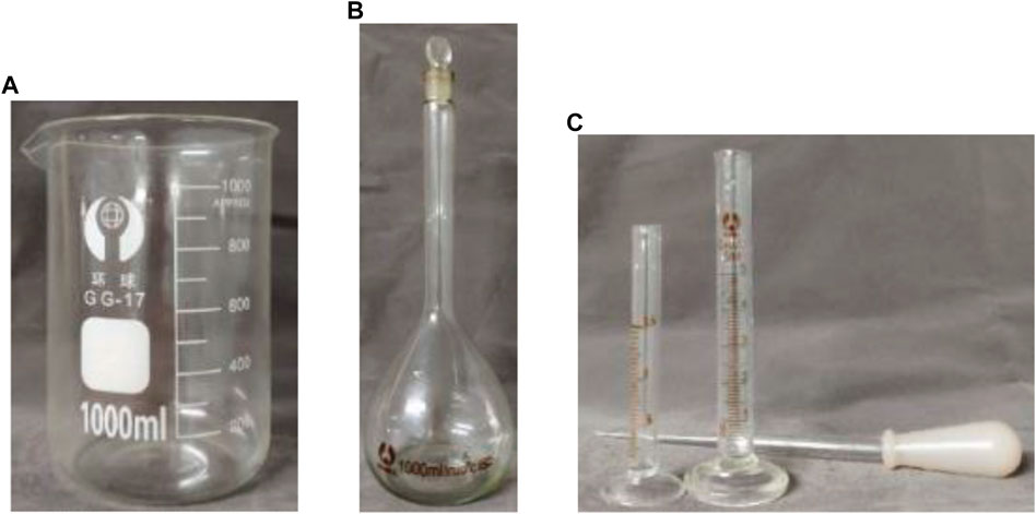
FIGURE 5. The facilities used to measure oil concentration. (A) beaker (B) long-necked vessel (C) a graduated cylinder and pipette.
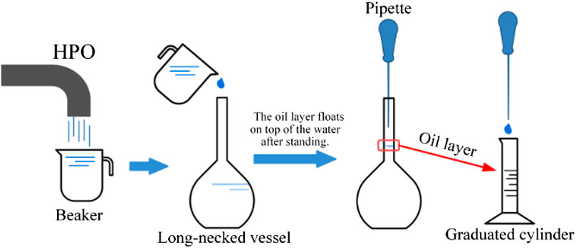
FIGURE 6. The measurement procedure.
3.5. Uncertainly Analysis
The accuracies of the measuring instruments in the experiment are shown in Table 3. The accuracies for the oil volume in the sample (Voil) and the volumetric flow rates of LPOs (QLPOs) are 0.05 ml and 0.1 L/s. Based on the uncertainties analysis method proposed by Kline and McClintock (Kline and McClintock, 1953), the relative uncertainty for controlled split ratio and oil concentration are 2.29% and 3.33%, respectively.
where F is a function of variables p1, p2, … pn; UF is the uncertainty for F, and upi is the uncertainty for the variable pi. The relative uncertainty for the factor λ can be written as
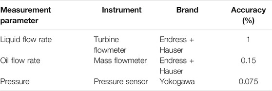
TABLE 3. Measurement parameters and their accuracies.
4. Experimental Results
4.1. Effect of Inlet Flow Rate
The effect of the inlet flow rate was investigated with an oil fraction of 10% under different water flow rates, when keeping the opening of valves at the outlets unchanged. The flow behavior inside the separator, recorded by the high-speed camera and the ordinary camera, is shown in Figure 7. A strong and stable oil core is developed in the upstream separation chamber and the diameter of the core is gradually reduced with the swirling liquids flowing downstream because the oil is drained from LPO1. Therefore, LPO1 decreases the drain load of LPO2. Additionally, the small droplets converge in the center after the acceleration of the strengthened swirler. A thin oil core can be observed in the downstream separation chamber. It is obvious that the first separation chamber plays the main role in separation. Most of the oil is separated successfully by LPO1 and LPO2. Only a few oil droplets that escaped from the first separation chamber flow downstream. Its diameter increased with the increasing inlet flow rate, which demonstrates that the separation efficiency of the upstream separation chamber reduced as well. The diameter of oil droplets decreases with the flow rate (Hinze, 1955), leading to a longer separation length. Moreover, the oil flow rate increases with the water flow rate when keeping the inlet oil fraction, leading to a large drain load for LPOs. Therefore, a larger flow rate brings higher difficulty for separation. Figure 8 represents the samples collected at different conditions after fully settling. The green layer floating on the surface is oil. Before the experiments, the oil was dyed with a green colorant to enhance the flow visualization, therefore ensuring that all green liquid is sucked out and measured. The results are shown in Table 4. In the water flow rate range of 4–6 m3/h, the conditions of 9% oil fraction were neglected. Because the minimum mark of the graduated cylinder shown in Figure 9 is 0.05 ml, the minimum oil concentration of 45 mg/L can be read. It can be seen that a higher flow rate leads to a higher oil concentration. When the flow rate is up to 7 m3/h, the oil concentration of HPO is approximately 89 mg/L via the measurement of a graduated cylinder. The change in pressure drop is shown in Figure 10. Obviously, a higher flow rate induces a larger pressure drop and the strengthened swirler contributes the most to the pressure drop.
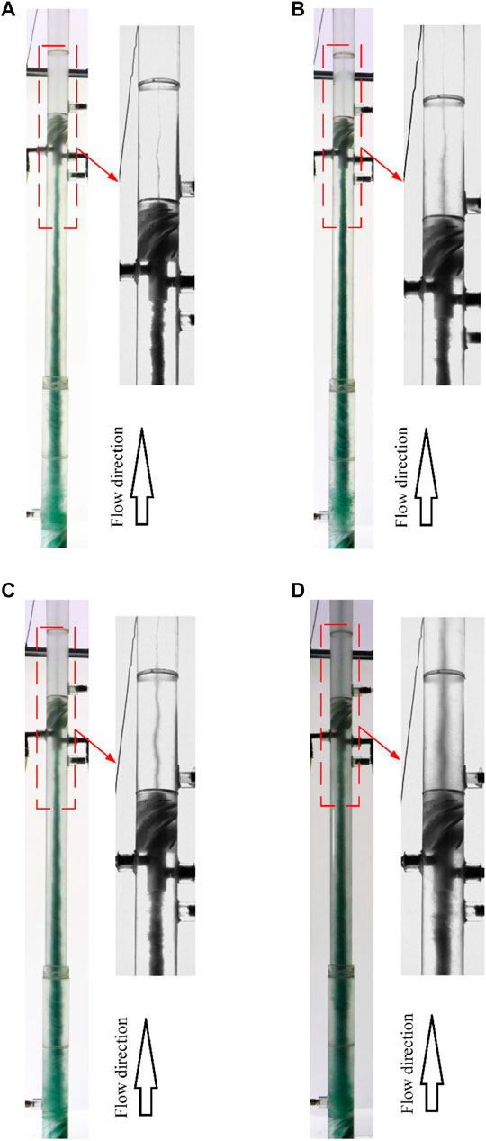
FIGURE 7. The flow behavior at different water flow rates. (A)Qwater = 4 m3/h (B)Qwater = 5 m3/h (C)Qwater = 6 m3/h (D)Qwater = 7 m3/h.
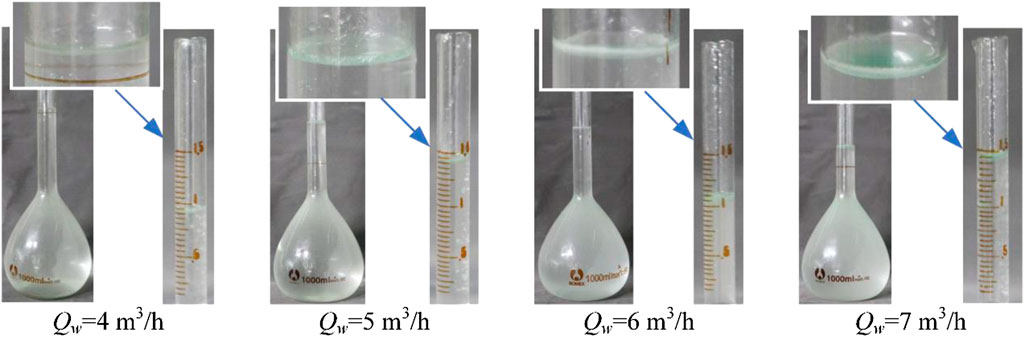
FIGURE 8. The samples at different flow rates.
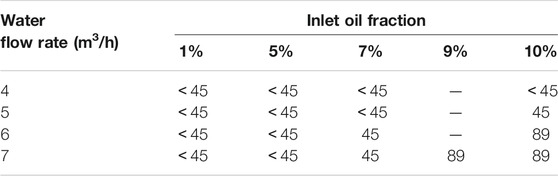
TABLE 4. The oil concentration (mg/L) at different conditions.
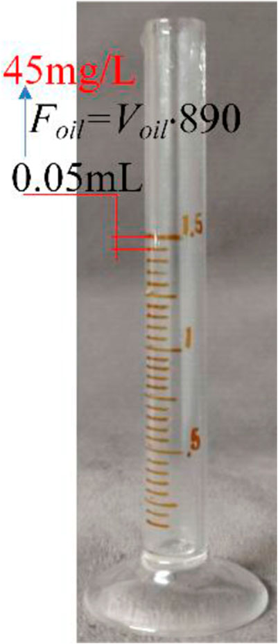
FIGURE 9. The graduated cylinder.
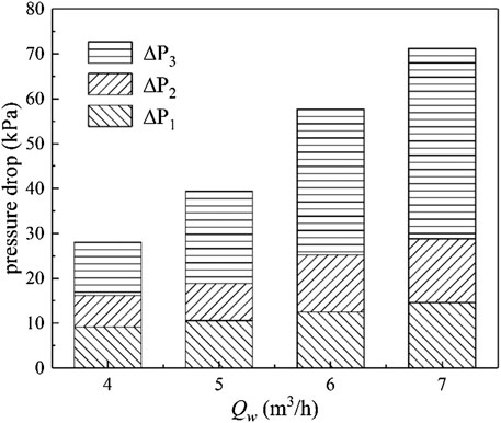
FIGURE 10. Pressure drop at different flow rates.
4.2. Effect of Inlet oil Fraction
To investigate the effect of inlet oil fraction on separation performance, the experiments were carried out at different oil fractions with a water flow rate of 7 m3/h. The photograph of the experimental flow behavior is shown in Figure 11.
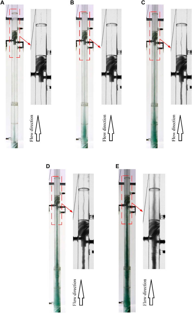
FIGURE 11. The flow behavior at different inlet oil fractions. (A) β = 1% (B) β = 5% (C) β = 7% (D) β = 9% (E) β = 10%.
Similarly, the diameter of the oil core increased gradually with the oil fraction. From Figure 11A, some bubbles in the center can be observed in the downstream separation chamber. The seal of the experimental system was checked and the gas core is also shown, which is the result of the dissolved gas that comes out (Gomez et al., 2001). In low oil fraction conditions, the oil droplets can be totally segregated from water in the first separation chamber. When the inlet oil fraction is up to 10%, the oil core covers the hub of the strengthened swirler. The number of droplets escaping into the downstream separation chamber increases as well. Furthermore, the oil concentration in HPO increases and the separation efficiency declines, as shown in Figure 12 and Table 4. The oil concentration is therefore less than 100 mg/L. From the experimental results, the conditions with low oil fraction have very high separation efficiency. Therefore, the controlled split ratio should be decreased to achieve high economy. Figure 13 illustrates the controlled split ratio change at different oil fractions. The controlled split ratio increased first and decreased when the inlet oil fraction exceeded 9%. A similar tendency was shown in other water flow rate conditions, which was caused by the inner pressure change with the oil core diameter. The tendency of a controlled split ratio at different conditions where the lower oil fraction leads to a lower controlled split ratio when the inlet oil fraction is below 9%, demonstrates that the separator has a self-adjusting ability, which significantly decreases manual operation in practical application.
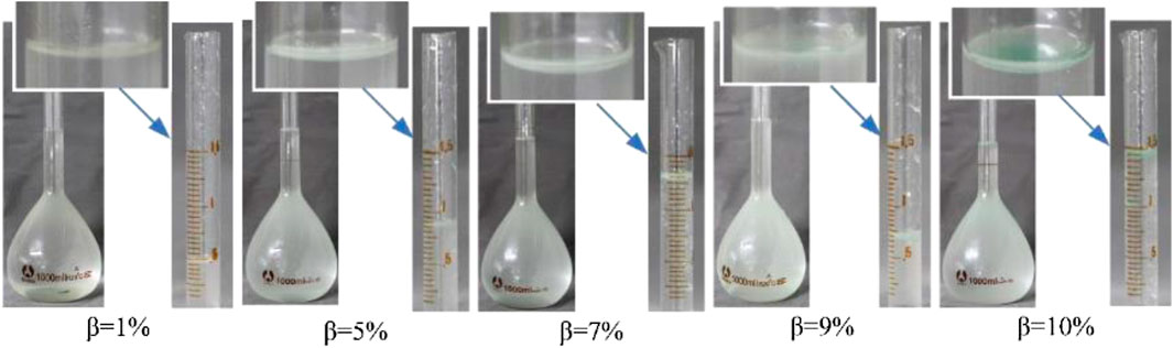
FIGURE 12. The samples collected at different oil fractions.
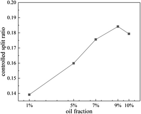
FIGURE 13. The change of controlled split ratio at different oil fractions.
4.3. Effect of Controlled Split Ratio
According to the previous research, the controlled split ratio has a serious impact on separation efficiency and a larger controlled split ratio could improve tangential velocity (van Campen, 2014). As centrifugal separators, it is not only important that sufficient centrifugal force be provided for dispersed droplets to move inward, but it also ensures that a continuous oil core is segregated from streams. A controlled split ratio is an important parameter that evaluates the ratio of the drain flow rate of LPOs to the inlet flow rate. The numerical research shows that the oil fraction is highest in the center and decreases with radius position (Wang et al., 2015). Thus, a large controlled split ratio is conducive to decreasing the oil concentration of HPO while the large controlled split ratio also results in high costs. If the controlled split ratio is too small, the oil core cannot be drained in time and the oil will flow from HPO, hampering the separation performance. For a well-designed separator, the controlled split ratio and oil concentration in HPO should both be considered. In this paper, the effect of a controlled split ratio was investigated with a water flow rate of 5 m3/h and an inlet oil fraction of 10%. Additionally, the controlled split ratio was controlled by the valve mounted on HPO, as shown in Figure 3. Figure 14 indicates the changes in oil concentration and the pressure drop at different controlled split ratios. When the controlled split ratio is 0.132, the oil concentration is up to 11,926 mg/L and the pressure drop is 42.7 kPa. It can be seen that a higher controlled split ratio has a favorable effect on the separation performance. This is because the larger controlled split ratio ensures that the oil core can be drained successfully. In a higher controlled split ratio condition, the pressure drop decreases because the flow rate of the liquids flowing through the strengthened swirler is reduced. Thus, to keep a high separation efficiency, the controlled split ratio should be maintained in a reasonable region to ensure that the oil core can be discharged successfully.
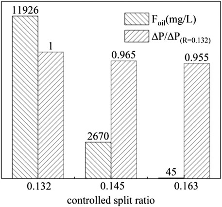
FIGURE 14. The oil concentration and pressure drop at different controlled split ratios.
5. Conclusion
In this paper, a new axial oil-water separator with two reverse flow outlets and a downstream flow outlet was designed. Additionally, the effects of an inlet flow rate, inlet oil fraction, and a controlled split ratio were investigated experimentally. From the discussion above the following conclusions can be made:
(1) The separator keeps a high efficiency in a water flow rate range of 4–7 m3/h with an oil fraction of 1%–10%. The oil concentration of the liquid collected from HPO was less than 100 mg/L in the experimental range when the controlled split ratio was maintained at a reasonable value.
(2) High inlet flow rate and oil fraction are inconducive to separation efficiency. The pressure drop increased with the increase of the flow rate. Additionally, the strengthened swirler contributes most to the pressure drop of the separator. The change tendency of a controlled split ratio increases first and then declines after, when the inlet oil fraction is improved from 1% to 10%.
(3) A controlled split ratio has a serious impact on separation performance. A large controlled split ratio can ensure that the oil core is discharged successfully.
(4) The separator in this paper was designed for the condition where the inlet oil fraction is below 10%, while the separation downhole is put into use in the condition with a larger oil content. Therefore, the structure optimization should be carried out to extend the application range of the separator.
Data Availability Statement
The original contributions presented in the study are included in the article/Supplementary Material, further inquiries can be directed to the corresponding author.
Author Contributions
WY and CY put forward the idea for the separator. MZ, FZ, and CL designed and bulit the experimental system. HW, PG, QS, and XZ conduct the experiments and data processing.
Funding
CNOOC energy development key project “development of compact and efficient oil field output processing technology and equipment development” Project No. HLXMLZ-GJ2018–15.
Conflict of Interest
Authors MZ, WY, FZ, CL, PG and QS were employed by the company CNOOC Ener Tech-Drilling and Production Co. Author HW was employed by the company Tianjin Branch of CNOOC Ltd.
The remaining authors declare that the research was conducted in the absence of any commercial or financial relationships that could be construed as a potential conflict of interest.
References
Al-Kayiem, H. H., Osei, H., Hashim, F. M., and Hamza, J. E. (2019). Flow structures and their impact on single and dual inlets hydrocyclone performance for oil-water separation. J Petrol Explor Prod Technol. 9 (4), 2943–2952. doi:10.1007/s13202-019-0690-1
Bowers, B. E., and Brownlee, R. F. (1998). Development of a downhole oil/water separation and reinjection system for offshore application. Texas, TX: Offshore Technology Conference.
Chang, Y. F., and Hoffmann, A. C. (2015). A Lagrangian study of liquid flow in a reverse-flow hydrocyclone using positron emission particle tracking. Exp. Fluid. 56 (1), 1–14. doi:10.1007/s00348-014-1875-5
Delfos, R., Murphy, S., Stanbridge, D., Olujić, Ž., and Jansens, P. J. (2004). A design tool for optimising axial liquid-liquid hydrocyclones. Miner. Eng. 17 (5), 721–731. doi:10.1016/j.mineng.2004.01.012
Gomez, C., Caldentey, J., Wang, S., Gomez, L., Mohan, R, and Shoham, O., (2001). Oil-water separation in liquid-liquid hydrocyclones (LLHC)—experiment and modeling, the 2001 SPE annual technical conference and exhibition. New Orleans, Louisiana: Louisiana.
Hamza, J. E., Al-Kayiem, H. H., and Lemma, T. A. (2020). Experimental investigation of the separation performance of oil/water mixture by compact conical axial hydrocyclone. Thermal Science and Engineering Progress. 17, 100358. doi:10.1016/j.tsep.2019.100358
Hinze, J. O. (1955). Fundamentals of the hydrodynamic mechanism of splitting in dispersion processes. AIChE J. 1 (3), 289–295. doi:10.1002/aic.690010303
Husveg, T., Rambeau, O., Drengstig, T., and Bilstad, T. (2007). Performance of a deoiling hydrocyclone during variable flow rates. Miner. Eng. 20 (4), 368–379. doi:10.1016/j.mineng.2006.12.002
Kline, S. J., and McClintock, A, M. (1953). Describing uncertainties in single-sample experiments. Mechanical Engineering. 75, 3–8.
Kou, J., Chen, Y., and Wu, J. (2020). Numerical study and optimization of liquid-liquid flow in cyclone pipe. Chemical Engineering and Processing - Process Intensification. 147, 107725. doi:10.1016/j.cep.2019.107725
Liu, S., Yan, Y., and Gao, Y. (2018). Optimization of geometry parameters with separation efficiency and flow split ratio for downhole oil-water hydrocyclone. Thermal Science and Engineering Progress. 8, 370–374. doi:10.1016/j.tsep.2018.08.011
Maddahian, R., Asadi, M., and Farhanieh, B. (2012). Numerical investigation of the velocity field and separation efficiency of deoiling hydrocyclones. Petrol. Sci. 9 (4), 511–520. doi:10.1007/s12182-012-0236-3
Motin, A., and Bénard, A. (2017). Design of liquid-liquid separation hydrocyclones using parabolic and hyperbolic swirl chambers for efficiency enhancement. Chem. Eng. Res. Des. 122, 184–197. doi:10.1016/j.cherd.2017.04.012
Noroozi, S., and Hashemabadi, S. H. (2011). CFD analysis of inlet chamber body profile effects on de-oiling hydrocyclone efficiency. Chem. Eng. Res. Des. 89 (7), 968–977. doi:10.1016/j.cherd.2010.11.017
Noroozi, S., and Hashemabadi, S. H. (2009). CFD simulation of inlet design effect on deoiling hydrocyclone separation efficiency. Chem. Eng. Technol. 32 (12), 1885–1893. doi:10.1002/ceat.200900129
Noroozi, S., Hashemabadi, S. H., and Chamkha, A. J. (2013). Numerical analysis of drops coalescence and breakage effects on de-oiling hydrocyclone performance. Separ. Sci. Technol. 48 (7), 991–1002. doi:10.1080/01496395.2012.752750
Saidi, M., Maddahian, R., and Farhanieh, B. (2013). Numerical investigation of cone angle effect on the flow field and separation efficiency of deoiling hydrocyclones. Heat Mass Tran. 49 (2), 247–260. doi:10.1007/s00231-012-1085-8
Schuetz, S., Mayer, G., Bierdel, M., and Piesche, M. (2004). Investigations on the flow and separation behaviour of hydrocyclones using computational fluid dynamics. Int. J. Miner. Process. 73 (2-4), 229–237. doi:10.1016/s0301-7516(03)00075-9
Schütz, S., Gorbach, G., and Piesche, M. (2009). Modeling fluid behavior and droplet interactions during liquid-liquid separation in hydrocyclones. Chem. Eng. Sci. 64 (18), 3935–3952. doi:10.1016/j.ces.2009.04.046
Shi, S.-y., Xu, J.-y., Sun, H.-q., Zhang, J., Li, D.-h., and Wu, Y.-x. (2012). Experimental study of a vane-type pipe separator for oil-water separation. Chem. Eng. Res. Des. 90 (10), 1652–1659. doi:10.1016/j.cherd.2012.02.007
Tang, B., Xu, Y.-x., Song, X.-f., Sun, Z., and Yu, J.-g. (2017). Effect of inlet configuration on hydrocyclone performance. Trans. Nonferrous Metals Soc. China. 27 (7), 1645–1655. doi:10.1016/s1003-6326(17)60187-0
Tang, B., Xu, Y., Song, X., Sun, Z., and Yu, J. (2015). Numerical study on the relationship between high sharpness and configurations of the vortex finder of a hydrocyclone by central composite design. Chem. Eng. J. 278, 504–516. doi:10.1016/j.cej.2014.11.022
van Campen, L. (2014). Bulk dynamics of droplets in liquid-liquid axial cyclones, Tu Delft, Netherlands: Tu Delft Publications.
Vieira, L. G. M., and Barrozo, M. A. S. (2014). Effect of vortex finder diameter on the performance of a novel hydrocyclone separator. Miner. Eng. 57, 50–56. doi:10.1016/j.mineng.2013.11.014
Vieira, L. G. M., Silvério, B. C., Damasceno, J. J. R., and Barrozo, M. A. S. (2011). Performance of hydrocyclones with different geometries. Can. J. Chem. Eng. 89 (4), 655–662. doi:10.1002/cjce.20461
Wang, J., Bai, Z., Yang, Q., Fan, Y., and Wang, H. (2016). Investigation of the simultaneous volumetric 3-component flow field inside a hydrocyclone. Separ. Purif. Technol. 163, 120–127. doi:10.1016/j.seppur.2016.02.022
Wang, L., Feng, J., Gao, X., and Peng, X. (2017). Investigation on the oil-gas separation efficiency considering oil droplets breakup and collision in a swirling flow. Chem. Eng. Res. Des. 117, 394–400. doi:10.1016/j.cherd.2016.10.033
Wang, S., Wang, D., Yang, Y., and Zhang, X. (2015). Phase-isolation of upward oil-water flow using centrifugal method. Flow Meas. Instrum. 46, 33–43. doi:10.1016/j.flowmeasinst.2015.09.005
Young, G. A. B., Wakley, W. D., Taggart, D. L., Andrews, S. L., and Worrell, J. R. (1994). Oil-water separation using hydrocyclones: an experimental search for optimum dimensions. J. Petrol. Sci. Eng. 11 (1), 37–50. doi:10.1016/0920-4105(94)90061-2
Zeng, X., Yan, C., Fan, G., Cheng, J., Xu, Y., Liu, A., et al. (2020a). “Experimental study on two different gas-liquid separators under different flow patterns,” in International conference on nuclear engineering. Virtual, Online: American Society of Mechanical Engineers, V003T12A021.
Zeng, X., Fan, G., Xu, J., Liu, A., Xu, Y., Yan, C., et al. (2020b). Experimental study on a new gas-liquid separator for a wide range of gas volume fraction. Chem. Eng. Res. Des. 160, 561–570. doi:10.1016/j.cherd.2020.06.004
Zeng, X., Zhao, L., Fan, G., and Yan, C. (2021a). Experimental study on the design of light phase outlets for a novel axial oil-water separator. Chem. Eng. Res. Des. 165, 308–319. doi:10.1016/j.cherd.2020.11.008
Zeng, X., Zhao, L., Zhao, W., Hou, M., Zhu, F., Guangming, G., et al. (2021b). Experimental study on a compact axial separator with conical tube for liquid-liquid separation. Separ. Purif. Technol. 257, 117904. doi:10.1016/j.seppur.2020.117904
Zeng, X., Zhao, L., Zhao, W., Hou, M., Zhu, F., Fan, G., et al. fnm (2020c). Experimental study on a novel axial separator for oil-water separation. Ind. Eng. Chem. Res. 59 (48), 21177–21186. doi:10.1021/acs.iecr.0c03913
Zhen-bo, W., Yi, M., and You-hai, J. (2011). Simulation and experiment of flow field in axial-flow hydrocyclone. Chem. Eng. Res. Des. 89 (6), 603–610. doi:10.1016/j.cherd.2010.09.004
Keywords: oil-water separation, axial separator, experimental investigation, separation efficiency, reverse flow
Citation: Zhan M, Yang W, Zhang F, Luo C, Wu H, Guo P, Shen Q, Zeng X and Yan C (2021) Experimental Investigation on the Separation Performance for a New Oil-Water Separator. Front. Energy Res. 8:608586. doi: 10.3389/fenrg.2020.608586
Received: 21 September 2020; Accepted: 28 December 2020;
Published: 16 February 2021.
Edited by:
Enhua Wang, Beijing Institute of Technology, ChinaReviewed by:
Hussain H. Al-Kayiem, Universiti Teknologi PETRONAS, MalaysiaYaxin Su, Donghua University, China
Copyright © 2021 Zhan, Yang, Zhang, Luo, Wu, Guo, Shen, Zeng and Yan. This is an open-access article distributed under the terms of the Creative Commons Attribution License (CC BY). The use, distribution or reproduction in other forums is permitted, provided the original author(s) and the copyright owner(s) are credited and that the original publication in this journal is cited, in accordance with accepted academic practice. No use, distribution or reproduction is permitted which does not comply with these terms.
*Correspondence: Changqi Yan, Q2hhbmdxaV95YW5AMTYzLmNvbQ==