 Tao Wang1
 Yinqiu Hong
- 1Institute of State Grid Hebei Electric Power Company Economic and Technological Research, Shijiazhuang, China
- 2School of Electrical Engineering, Southeast University, Nanjing, China
An integrated energy system is a promising approach to synthesize various forms of energy, where cooperative control is indispensable for stable and efficient operation. During the information exchange of cooperative distributed secondary control (DSC) in an integrated energy system, the effect of time delays on system performance cannot be ignored, which mainly consist of input delays and communication delays. Compared with most of the existing literature which only address DSC considering communication delays, this paper investigates the stability robustness of an integrated energy system in the case of both input and communication delays. First, the impacts of input and communication delays on DSC are analyzed based on the Gerschgorin theorem and Nyquist criterion, where the system stability is principally dependent on input delays while has little correlation with communication delays and the inconsistency of the two delays may result in steady-state deviation. Then, on the assumption of identical input and communication delays, a closed-loop small-signal model equipped with a distributed secondary controller is established for stability analysis and the delay-dependent criteria are formulated to determine the stability margin of the system based on critical characteristic root tracking. By a series of trial declarations, the delay margins with regard to different controller gains are determined and the qualitative relationship between delay margins and controller gains can be utilized to guide the controller design for improved system performance. The effectiveness of the theoretical results is verified by case studies on a test system.
Introduction
The concept of an integrated system installed with multiple forms of renewable energy has been promoted for better exploitation of its advantages. However, the stochasticity and intermittency of distributed generations (DGs) could degrade the reliability and power quality of the system. Besides, considerable differences between the peak and valley loads would lead to an inefficient energy utilization. To address these challenges, the storages within the integrated system are equipped to smooth out the fluctuation of output power as well as implement power dispatch (He and Li, 2011; Yu et al., 2016; Wang et al., 2019a). As one of the most attractive features, the integrated system can be operated in island mode in case of planned or spontaneous events, to provide an uninterrupted power supply to customers (Jin et al., 2014; Han et al., 2018). With the superiority of low complexity and energy loss, the integrated system has a promising future to be evolved into a possible DC structure (Morstyn et al., 2016; Yoo et al., 2020). A reliable control scheme is of great significance in ensuring the safe and stable operation of the system. To meet the requirement of spontaneous power sharing without communication, droop control, which takes the virtue of the relationship between power and voltage/frequency, is widely utilized. However, the presence of droop characteristics would produce poor power sharing due to the distinct output impedances of individual DGs, as well as diverse voltage deviation (Guo et al., 2014; Wang et al., 2019b).
To deal with the aforementioned defects, secondary control is introduced, varying from a centralized control structure to a distributed control structure. Centralized secondary control assumes a microgrid centralized controller (MGCC), which requires a global information collection and calculation (Lopes et al., 2006; Mehdi et al., 2020); however, it is sensitive to a single-point-of-failure. In recent years, inspired by multi-agent technology, distributed secondary control, in which each DG exchanges information with its immediate neighbors via local networks, has gained a lot of popularity (Simpson-Porco et al., 2015; Guo et al., 2018; Kang et al., 2018; Lu et al., 2018). Nasirian et al. (2015), developed a complete dynamic model of the DC integrated system with a distributed control framework, and the guidelines for the controller design were given to optimize the dynamic performance. A novel distributed control strategy was proposed by Trip et al. (2018), where the secondary control objectives were achieved with consideration of the requirement of plug-and-play. Baranwal et al. (2019) proposed to improve system robustness under various uncertainties by distributed control methods based on robust algorithms. Moreover, distributed secondary schemes based on a smooth adaptive method was proposed to reinforce system robustness (Zuo et al., 2020), and the adaptive virtual resistance was introduced by Kumar and Pathak (2020) to reduce the overshoot during secondary control. Dou et al. (2017) presented H∞ algorithms to provide further system performance improvements.
The main feature of the existing literature on distributed control lies in the local-neighboring information exchange. During information collection and exchange, the time delays are unavoidable and it is important to study the impact of time delays on system performance, especially considering the increasing utilization of open communication infrastructures and the low inertia of inverter-interfaced DGs (Lou et al., 2018; Li and Shahidehpour, 2019). Broadly speaking, there exists two kinds of time delays among DGs, i.e., input delays and communication delays, where the former is in regard to the information collected and processed by the local DG and the latter is related to communication from one DG to another. Although the impact of communication delays on an integrated DG system have been extensively researched by Lou et al. (2018) and Liu et al. (2015) based on a small signal model through the critical characteristic root tracking method, there are few studies on the secondary control of an integrated energy system with input delays, to the best of our knowledge. Olfati-Saber and Murray (2004) proposed a delay-dependent distributed control, in which each agent delays its local measurements as the same number as communication delays, that is, matched input and communication delays are assumed. However, these two delays generate from different sources and they are not the same number in many cases. Therefore, it is necessary to investigate the impact of both input delays and communication delays on the distributed secondary control of an integrated energy system.
Motivated by the aforementioned research gap, this paper investigates the stability robustness of a DC microgrid taking both input and communication delays into consideration. First, upon the consensus-based secondary control of the integrated energy system, input delays and communication delays are separately introduced, compared to most of the existing DSC literature which only addresses communication delays. Then, based on the Nyquist criterion and Gerschgorin theorem, the sufficient condition for delayed-system consensus is derived, from which we can observe that the stability of the integrated system mainly depends on input delays, and the system performance in the presence of communication delay could be ameliorated in company with a moderate input delay. For the sake of better system performance, a synchronous interaction case with an identical number of input delays and communication delays is expected and discussed, where a closed-loop small-signal model for a DC integrated energy system is established and the delay margin calculation method is provided by virtue of tracing the critical characteristic root. By a series of trial declarations, the relationship between control parameters and stability robustness is determined to guide the controller design.
The remainder of this paper is organized as follows: Problem Formulation section reviews the hierarchical control of DC integrated energy systems and delay-dependent secondary control. The respective formulation and impacts of input delays and communication delays are investigated in Impact of Input and Communication Delays on System Performance section, and the sufficient condition for system stability is derived. In Stability Robustness with Identical Input and Communication Delays section, the procedures for delay margin determination are introduced considering the concurrence of input and communication delays. A case study based on a test DC MG is conducted to investigate the relationship between the control gains and delay margins and the effectiveness of the theoretical results are demonstrated by simulation in Simulation Results section.
Problem Formulation
Hierarchical Control of a DC Integrated Energy System
The hierarchical control structure is displayed in Figure 1, which includes primary control and secondary control, with droop control widely adopted as primary control to ensure system stability:
where Vi and Vni represent the actual output and nominal voltages of the ith DG, mi denotes the droop coefficient, and Pi denotes the measured active power.
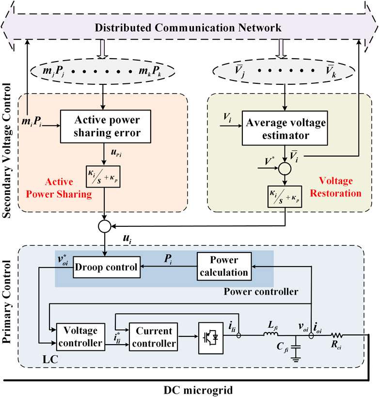
FIGURE 1. Hierarchical control structure of the DC microgrid.
To achieve accurate power sharing and eliminate voltage deviation in the presence of droop control, secondary control is introduced by adding an auxiliary term ui on the basis of Eq. 1:
The control objective of proportional sharing requires active power to allocate according to the inverse of the droop coefficient between DGs, i.e., m1P1 = m2P2 = … = mnPn. Based on average consensus protocol, the controller for power sharing can be designed as:
where ki1 represents the integral gain of power sharing controller and aij represents the communication weight, with aij = 1 implying the existence of a communication link between the ith and jth DG and aij = 0 implying otherwise.
In view of the contradiction between voltage restoration and proportional power sharing, the average voltage is always taken to be regulated to the nominal value in practice. Given the absence of a global controller, the average voltage will be estimated locally utilizing a distributed observer:
where
where ki2 denotes the integral gain of the voltage restoration controller. It can be observed from Eq. 3 and Eq. 4, based on the distributed information exchange, the active powers and estimated average voltages of DGs converge to a common state.
Delay-Dependent Consensus Algorithm
In most of the existing literature on DSC, the time delays with regard to the transmission among local-neighboring DGs are considered for system stability analysis. Then, each DG obtains decision control based on the delayed state information from neighbors and its current state, i.e., mismatched time delays. Alternatively, based on the delayed-consensus protocol put forward by Olfati-Saber and Murray (2004), active power sharing can be formulated in a symmetric format as follows:
where τij is denoted as communication delays in regard to the information exchange between DGi and DGj. It can be observed that the local DGi delayed its own measurements by the same amount as the communication delays so that the states of its own and its neighbors were with the same time instant. Actually, the delays intentionally introduced by the agent itself during the processing of local data can be considered as input delays, which refer to signal collection and signal modulation/demodulation, while the communication delays contain not only signal collection and signal modulation/demodulation, but also packet organization format and signal transmission. Generally, communication delays for signals from neighboring DGs are larger than those from local DGs. Protocol (6) is applicable upon the assumption of identical input and communication delays; however, the time delay can be affected by multiple factors in practice, e.g., communication link and hardware facilities and it does not apply to the case of diverse delays. Therefore, a more universal form of the consensus algorithm can be formulated as:
where τ represents the local input delay, which is related to the procedure of information collecting and processing as well as actuator and controllers. Employing consensus protocol Eq. 7 in microgrids, the power sharing controller can be designed as:
Homoplastically, the average voltage estimation can be given by:
As can be deduced from Eq. 8 and Eq. 9, these two kinds of delays could exert diverse influence on system performance, which indicates the significance of stability analysis of the MG system taking both input and communication delays into consideration.
Impact of Input and Communication Delays on System Performance
In this section, the stability issue with regard to input and communication delays will be thoroughly investigated. Firstly, some useful lemmas are introduced.
Lemma 1 (Ren and Beard, 2005): 0 is a single root of the Laplacian matrix L if there exists a global reachable node.
Lemma 2 (Massoulie, 2002): For any γ ∈ [0,1), −1+j0 is not included in the convex hull γCo(0 ∪ {Ei(jω), i∈N}) if ω∈R, where
Lemma 3 (Meng et al., 2011): For ω ∈ R, the disc is contained in the convex hull γCo(0 ∪ {Wi(jω), i∈N}).
Theorem 1: Once the inequality Eq. 10 holds, the states will converge to the consensus value asymptotically, where di = ∑vj∈Niaij.
Proof: Under the unified consensus protocol in Eq. 7, the dynamic of active power can be modeled as:
where Cp denotes the interaction strength. Performing Laplace transformation on Eqs 11, 12 follows:
Then, the characteristic equation of the system can be derived as det(sI + L(s)) = 0. Where I is an identity matrix with n dimensions and L(s) is defined as:
It can be deduced from lemma 1 that 0 is a single root of the characteristic equation. Defining P(s) = det(I + G(s)), where G(s) = L(s)/s, then obviously, the zeros of P(s) are equivalent to the non-zero roots of the characteristic equation.
According to the Gerschgorin theory, the eigenvalues of G(jω) lie in a disc:
where
and C represents the complex field. Premising the line between the origin and the center of disc, which can be obtained as
According to Lemma 2, it can be derived that Wi(jω) = γiEi(jω) with γi = 4diT/π. On account of the condition max{diτ}<π/4, defining γ = max{γi, i∈N} and apparently, the following relationship holds:
Employing Lemma 2, it can be deduced that −1+j0 is not included in the set Co(0 ∪{Wi(jω), i∈N}). Further combined with lemma 3 as well as the Gerschgorin theory, the conclusion can be drawn that the root locus of G(jω) will not pass −1+j0. According to the generalized Nyquist criterion, all zeros of P(s) will have negative real parts, i.e., the system will converge asymptotically and the proof of Theorem 1 are completed.
From the sufficient condition for system stability Eq. 10, we can conclude that whether the system under the consensus protocol in Eq. 7 achieves consensus mainly depends on the input delays while it has a weak association with communication delays. Therefore, it is critically important to investigate the impact of input delays on system performance rather than only considering communication delays, in contrast to most of the existing delay-dependent analyses of distributed secondary control in MGs. Generally, input delays are relatively negligible compared to communication delays in practice. However, great distinction between the two kinds of delays will introduce information disorder for decision-making due to local-neighboring state interaction, which could definitely give rise to steady state deviation (Fatihcan, 2010). To avoid the aforementioned steady deviation, auxiliary methods are usually applied to ensure that the local and neighbors’ information comes from the same time instant, that is, the local information is delayed in an identical way to the communication delays. In practical implementation, the previous information of each DG is saved by signal storage devices and the local information with the same timestamp as the neighboring information can be obtained from the device once the signal from neighboring nodes is received. Thus, the control decision will be made using the local and neighboring information from the same timestamp, i.e., the communication and input delays are controlled so they are uniform.
Stability Robustness With Identical Input and Communication Delays
In this section, we consider secondary voltage control under the theoretical assumption of identical communication delays and input delays. Considering that the communication delays during information exchange are inevitable and much larger than input delays in practice, whereas the inconformity between the input and communication delays may result in equilibrium deviation, the state in local DG is usually delayed similarly to communication delay, to come at an agreement of information instants. It should be noted that the communication delay can be determined based on the offset between the sending timestamp T1 and the receiving timestamp T2.
With the increase of input delays, the system performance is degraded and even leads to instability in the worst case. In this section, the stability robustness of distributed secondary control with input and communication delays is addressed. Firstly, a small signal model of MG is derived, taking time delays and controller parameters into consideration. Then, the delay margin as the maximum delay under which the system can maintain stable is determined and the relationship between the controller gains and delay margin is investigated to guide the controller design.
Small-Signal Modeling of a DC Integrated System
The closed loop small-signal model of a DC microgrid installed with time delays is established first, consisting of three parts: the inverters, network, and loads.
The inverters are controlled by the hierarchical control strategy mentioned in Impact of Input and Communication Delays on System Performance section. The voltage regulation to the reference value can be implemented with the assistance of the voltage and current double-loop controller:
where Voi denotes the actual output voltage; ioi and iref denote the actual output and reference currents, respectively; kpv, kiv, kpi, and kii are the proportional and integral gains of the PI controllers; and di represents the duty cycle. Whereas in practice, considering the much faster response of voltage and current loop compared with the power loop, the dynamic of primary control can be assumed to be equivalent to that of the power controller. Further considering the employment of the virtual resistance technique, the reference for the virtual output voltage of the inverter can be obtained from the droop equation and the actual output voltage reference can be provided by:
where Vvi represents the virtual output voltage; rvi represents the virtual resistance; Ii denotes the output current, and ui can be obtained from Eqs 3–5 in Impact of Input and Communication Delays on System Performance section. As can be deduced from the equation, the effect of adding the virtual resistance is equivalent to essentially changing the droop gain in DC systems. Hence, the term in regard to virtual resistance can be omitted in subsequent analysis for simplification. Besides, the active power in the equation can be measured through a low-pass filter:
where ωf is the cutoff frequency.
By differentiating and linearizing the above Eqs. 16, 17, the small-signal model of inverters can be established as:
where
The inverters are supposed to be connected to the network as depicted in Figure 2.
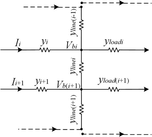
FIGURE 2. Network configuration.
According to the circuit configuration, the output current can be modeled as:
where Y = diag(yi), with yi denoting the output admittance of the ith DG and Vb = [Vb1, Vb2, …, Vbn]T with Vbi denoting the ith bus voltage. The relationship between the bus voltage and the output voltage of DGs can be established using the node voltage equation:
where ysi= ylinei + yline(i-1)+yi + yloadi; ylinei represents the line admittance between the ith and (i+1)th DG and yloadi represents the admittance of the ith load.
Further, based on the integration of Eqs 19 and 20, the small-signal model of output current can be established as:
where Y′ = Y(1−Ys−1Y) is the admittance matrix with
By substituting (Eq. 20) into (Eq. 17), the closed-loop small-signal model for the whole system without delay can be obtained as:
where A is the system parameter matrix and can be derived as A = A′+BY′H, where H = [0n×nIn×n0n×n].
Further, we assume a uniform delay of τ during local data processing and information interaction, then Eqs 3 and 4 can be replaced as:
Correspondingly, (Eq. 22) can be modified and the complete delay-dependent small-signal model can be acquired as:
where A1 and Ad are coefficient matrices given in the Appendix.
Critical Characteristic Root Tracking Method
The stability of a DC microgrid installed with delay will be analyzed based on the small-signal model established previously in this section. Equation 25 yields the characteristic equation of the system:
According to the stability criterion for a closed-loop system, it can be deduced that the system is stable when all the eigenvalues of Eq. 26 have a negative real component. Whereas the solution of Eq. 26 would be challenging to acquire directly due to the existence of the transcendental item. Therefore, the method of critical characteristic root tracking will be introduced to reduce the complexity of this problem (Jia and Yu, 2008).
Considering the pure imaginary root corresponds to the critical stable state of the system, the stability switch can be assumed to take place accompanied by the occurrence of a pure imaginary root. Provided the equation has a pure imaginary solution jωc, then there is
and jωc will be one of the eigenvalues of Eq. 26. It can be noticed that the transcendental item
where sgn(·) represents the sign function, with possible values of 0, 1, and −1 corresponding to zero, positives, and negatives, respectively; Re(·) represents the real component of a complex. It can be deduced from the definition that the condition RT = 1 ensures a state transition of the system from instability to stability as the communication delay τ increases.
Ultimately, n satisfactory values of delay margin will be calculated and screened out as τc1, τc2, …, τcn and the delay margin can then be determined as the minimum of the feasible values, i.e., τd = min{τc1, τc2, …, τcn}.
To summarize, the delay-dependent stability analysis includes the following steps:
Step 1: Establish the closed-loop small-signal model for the whole system considering communication delays;
Step 2: Designate control parameters and acquire the characteristic equation related to ξ;
Step 3: Change ξ within [0,2π] and track the root of the characteristic equation, calculate the corresponding τc as the candidate delay margin once the equation has a pure imaginary root;
Step 4: Calculate RT for each τc and screen out those with RT = 1 as τc1, τc2, …, τcn;
Step 5: Determine the delay margin as τd = min{τc1, τc2, …, τcn};
Step 6: Change control parameters and repeat steps 2–5. Investigate the impact of control parameters on delay margin.
In addition, it is worth noting that the aforementioned analysis is performed on the assumption that the dynamic of the inner loop is ignorable, whereas considering the premise is decided by the controller of the inner loop and is irrelevant to the major concern of secondary control in this paper, the analytical method in this section is still effective.
Simulation Results
In this section, simulations are performed for stability analysis with consideration of both input and communication delays by a test DC microgrid as presented in Figure 3, where three DGs are connected and communicate with each other. The control and system parameters are listed in Table 1, and active power is desired to be 1:1:1. The separate and comprehensive impacts of communication and input delays are investigated by employing various time delays. Then, to investigate the quantitative effect of controller gains on the system stability, the cases of different controller gain sets are performed. Simulation results using MATLAB/Simulink are utilized to verify the theoretical results. For the sake of simplicity, the controller gains of the two DGs are assumed to be same, and due to the small number of proportional gains in the PI controller, only the integral terms are utilized.
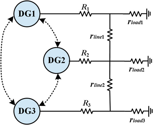
FIGURE 3. Architecture of the test microgrid.
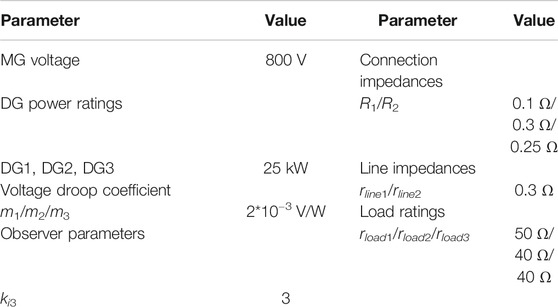
TABLE 1. Control and system parameters.
Impact of Input and Communication Delays on System Performance
In this case, the impact of input and communication delays on system performance is investigated. The islanded MG is controlled by droop control at the first stage and the distributed secondary control is launched at t = 3s. For a more intuitive comparison, simulation results of the delay-free case are displayed in Figure 4, from which we can see that stability is primarily guaranteed by droop control, whereas the system suffers from inaccurate power allocation and different voltage deviation. With the aid of secondary control at t = 3s, active power reallocates between DGs and voltage rises gradually. After a while, the system reaches a new equilibrium where active power has a 1:1:1 sharing between DGs and the average voltage arrives at the expected reference value, 800 V. Firstly, the input delay for each DG is set as τ = 30 ms, and different communication delays of τij = 0 ms, 30 ms, and 100 ms are performed, with the results shown in Figure 5. As can be visualized from Figure 5, the system remains stable regardless of the gradual increase of communication delay, implying that communication delays have negligible influence on system stability, which is consistent with the theoretical conclusion drawn in Stability Robustness with Identical Input and Communication Delays section. However, due to the inconsistency between input and communication delays (i.e., 0 ms or 100 ms for communication delays, 30 ms for input delays), the voltages and active powers deviate from the responses of the delay-free case shown in Figure 4, which indicates that communication delays could exert an influence on the steady-state error. Only when τij = τ = 30 ms do the responses appear to be the same as the accurate ones in Figure 4.
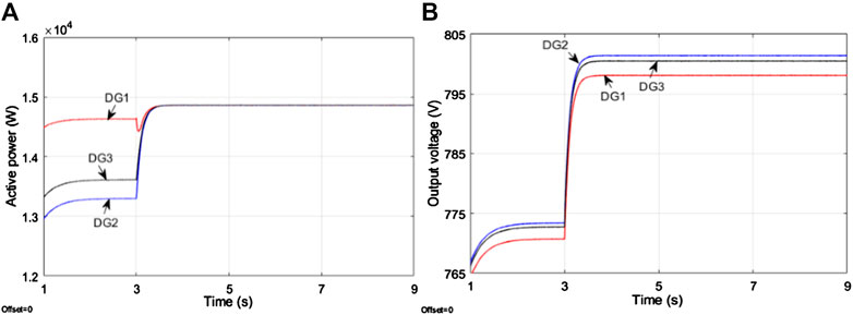
FIGURE 4. Simulation results of the case without time delay (A) Active powers (B) Output voltages.
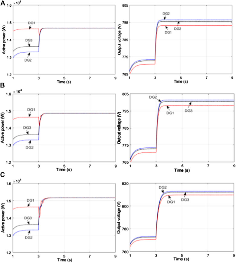
FIGURE 5. Simulation results of active powers and actual output voltages with different communication delays and a fixed input delay of τ = 30 ms (A)τij = 0 ms (B)τij = 30 ms (C)τij = 100 ms.
Further, the impact of input delays on the MG system is studied and the simulation operation is the same as above. The communication delay during individual information exchange is fixed as τij = 30 ms and different input delays of τi = 0 ms, 30 ms, and 60 ms are performed with the results shown in Figure 6. As can be observed from Figure 6, the MG system experiences steady-state deviation with τi = 0 ms, τij = 30 ms but reaches an accurate convergence with τi = 30 ms, τij = 30 ms. Therefore, a certain input delay would facilitate system performance. With an increase in the input delay, the responses undergo growing oscillations with τi = 60 ms, τij = 30 ms, which is in accordance with the theoretical stability constraint for input delay as τ < 39.3 ms derived from the stability sufficient condition Eq. 10 in this case. Therefore, the stability of the MG system is mainly dependent on input delays but has little correlation with communication delays, and moreover, the inconsistency between input delays and communication delays would result in convergence deviation, indicating that a moderate increase of input delays can contribute to the elimination of steady-state deviation in some practical cases.
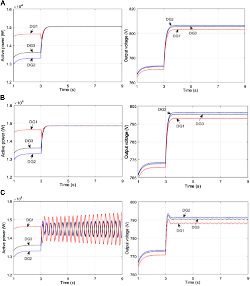
FIGURE 6. Simulation results of active powers and actual output voltages with various input delays and a fixed communication delay of τij = 30 ms (A)τ = 0 ms (B)τ = 30 ms (C)τ = 60 ms.
Relationship Between Control Gains and Delay Margin
Considering that the communication delays cannot be negligible and could cause precision degradation, the consensus protocol was proposed where the information of the local DG is delayed at the same rate as the communication delays of its neighbors. In this case, we will investigate the performance of distributed secondary control with the same input and communication delays to avoid the occurrence of convergence error due to mismatched states.
Theoretical Calculation of Delay Margin
Considering that the stability condition for delay is dependent on controller gains, the delay margin of the test system with various control gains will be calculated adopting the analysis method proposed in Simulation Results section. We will first take the case of ki1 = 12, ki2 = 10 as an example to illustrate the determination of the delay margin. The corresponding dominant root loci of the characteristic equation is displayed in Figure 7. Four feasible sets of {ω, ξ} are obtained, among which two sets satisfying the condition RT = 1 are singled out as {ωc1, ξc1} = {1.443, 5.931} and {ωc2, ξc2} = {1.628,18.550}, yielding a corresponding communication delay as τc1 = 243.3 ms and τc2 = 87.9 ms. Hence, the delay margin in this case can be obtained as τd = 87.9 ms. Then, similar operations are performed as the above procedures with different controller sets ki1 and ki2, the delay stability posture is generated as shown in Table 2. As can be observed from the table, the upper bound of the stability region shows a slight increase with a larger ki2 while the delay margin decreases apparently when ki1 becomes larger, i.e., a larger integral gain of the power sharing controller would lead to a worse stability robustness to delay while the integral gain of the voltage regulation controller has relatively less impact on system stability.

FIGURE 7. Dominant root loci of the case with ki1 = 12, ki2 = 10.
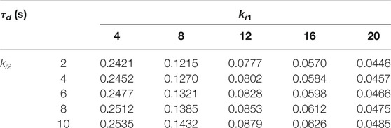
TABLE 2. Theoretical delay margin of the DC microgrid.
Simulation Results of Delay Margin
Simulations will be undertaken with two sets of controller gains in the presence of identical delays to verify the effectiveness of the proposed methodology. The selected sets of control parameters are marked in the table as ki1 = 12, ki2 = 10 and ki1 = 16, ki2 = 4. Initially, droop control operates in the DC microgrid and secondary control is launched at t = 3 s, with the simulation results depicted in Figures 8 and 9, respectively. It can be observed that in the delay-free case, accurate active power sharing and average voltage regulation is achieved after the secondary control is activated. In the case of ki1 = 12, ki2 = 10, considering the presence of time delay as shown in Figures 8(B),(C), the curves of active powers and output voltages show a decaying oscillation with time delay τ = 83 ms and recover to stability about 3 s later. However, as the time delay further increases to τ = 98 ms, oscillation enlarges and the MG system fails to remain stable. Then the delay margin with regard to this set of controller gains lies between τ = 83 ms and τ = 98 ms, according to the theoretical delay margin τd= 87.9 ms obtained from Table 2.
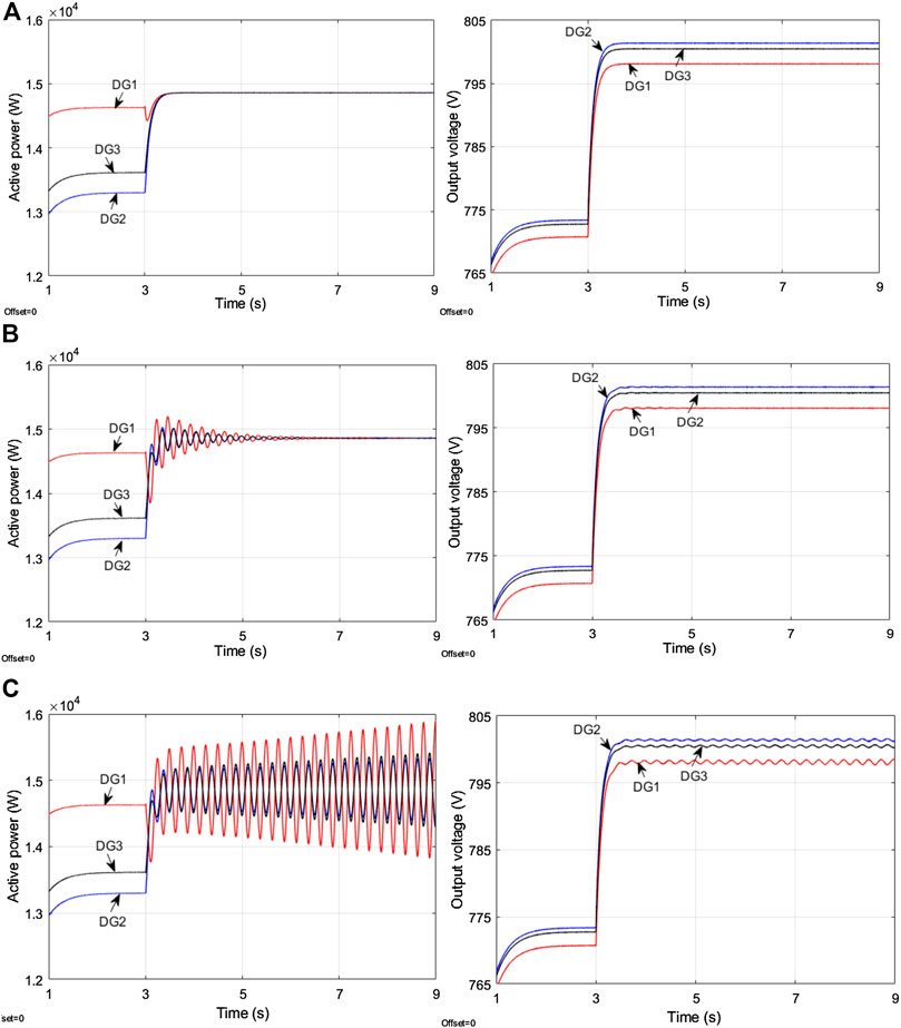
FIGURE 8. Simulation results of active powers and actual output voltages with various time delays under ki1 = 12, ki2 = 10 (A) Without delay (B)τ = 83 ms (C)τ = 98 ms.
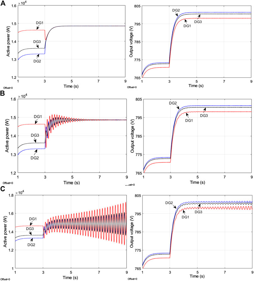
FIGURE 9. Simulation results of active powers and actual output voltages with various time delays under ki1 = 16, ki2 = 4 (A) Without delay (B)τ = 55 ms (C)τ = 65 ms.
Similarly, for the case of controller set ki1 = 16, ki2 = 4 as depicted in Figure 6, the system tends to be stable with a relatively small delay τ = 55 ms while the MG system becomes unstable when the delay increases to τ = 65 ms. Querying the theoretical result τd= 58.4 ms in Table 2, the effectiveness of the proposed analysis method is verified.
As can be visualized from the figures, similar dynamic performance is shown in the above two cases, whereas the control parameter set ki1 = 12, ki2 = 10 enjoys great superiority over that of ki1 = 16, ki2 = 4 in terms of delay-dependent stability. Therefore, the proposed stability analysis theory would be instructional for the design of control gains, to achieve a compromise between the dynamic performance and delay margin.
Conclusion
This paper addresses the stability analysis of distributed secondary control in DC integrated energy systems, taking both input and communication delays into consideration. Based on the Gerschgorin theorem and Nyquist criterion, the impact of input and communication delays on system stability is investigated and the stability condition is derived, from which we can observe that the stable operation mainly depends on input delays while is almost impervious to communication delays. However, the distinction between input and communication delays could give rise to steady-state error, indicating that a moderate increase of input delay can contribute to the elimination of steady-state deviation in some cases. The conclusion would be of great significance for control performance optimization in practice. Then, a small-signal model for stability analysis considering identical input and communication delays is derived and the delay margin corresponding to different control parameters can be calculated based on the critical characteristic root tracking method. The qualitative relationship between controller gains and delay margin can be utilized to guide the control design. Simulation cases are carried out to verify the effectiveness of the theoretical conclusions. Although the small-signal modeling is implemented in a small-scale system in this paper, the effectiveness of the approach remains regardless of the increasing number of DGs, considering that the small-signal method is always applicable for modeling DGs, and both the establishment and solution of the model can be executed by computers.
Data Availability Statement
The original contributions presented in the study are included in the article/Supplementary Material, further inquiries can be directed to the corresponding author.
Author Contributions
TW and CR proposed the methodology. TW and ST conducted the theoretical analysis as well as the simulation verification. QH wrote the original draft which was reviewed and edited by TW and CR All authors agree to be accountable for the content of the work.
Funding
This research was supported by the science and technology project of the State Grid Corporation of China, Grant 5204JY20000B.
Conflict of Interest
The authors declare that this study received funding from the science and technology project of the State Grid Corporation of China. The funder had the following involvement with the study: provide practical application scenario for the case study.
Appendix
A′ = R−1D, B = R−1E where
A1 = R−1D1, A1 = R−1Dd where
References
Baranwal, M., Askarian, A., Salapaka, S., and Salapaka, M. (2019). A distributed architecture for robust and optimal control of DC microgrids. IEEE Trans. Ind. Electron. 66, 3082–3092. doi:10.1109/TIE.2018.2840506
Dou, C., Yue, D., Guerrero, J. M., Xie, X., and Hu, S. (2017). Multiagent system-based distributed coordinated control for radial DC microgrid considering transmission time delays. IEEE Trans. Smart Grid 8, 2370–2381. doi:10.1007/s12555-019-0610-7
Fatihcan, A. M. (2010). Consensus in networks under transmission delays and the normalized Laplacian. IFAC Proc. Vol. 43, 277–282. doi:10.1098/rsta.2012.0460
Guo, F., Wen, C., Mao, J., and Song, Y. (2014). Distributed secondary voltage and frequency restoration control of drop-controlled inverter-based microgrids. IEEE Trans. Ind. Electron. 62, 4355–4364. doi:10.1109/TIE.2014.2379211
Guo, F., Xu, Q., Wen, C., Wang, L., and Wang, P. (2018). Distributed secondary control for power allocation and voltage restoration in islanded DC microgrids. IEEE Trans. Sustain. Energy 9, 1857–1869. doi:10.1007/s12555-019-0929-0
Han, Y., Zhang, K., Li, H., Coelho, E. A. A., and Guerrero, J. M. (2018). MAS-based distributed coordinated control and optimization in microgrid and microgrid clusters. Comprehens. Overview 33, 6488–6508. doi:10.1109/TPEL.2017.2761438
He, J., and Li, Y. W. (2011). Analysis, design, and implementation of virtual impedance for power electronics interfaced distributed generation. IEEE Trans. Ind. Appl. 47, 2525–2538. doi:10.3390/en11071801
Jia, H. J., and Yu, X. D. (2008). “A simple method for power system stability analysis with multiple time delays”, in Proceedings of 2008 IEEE power and energy society general meeting - conversion and delivery of electrical energy in the 21st century. Pittsburgh, PA, 20–24.
Jin, C., Wang, P., Xiao, J., Tang, Y., and Choo, F. H. (2014). Implementation of hierarchical control in DC microgrids. IEEE Trans. Ind. Electron. 61, 4032–4042. doi:10.1109/TIE.2013.2286563
Kang, W., Li, Q., Gao, M., Li, X., Wang, X., Xu, R., and Chen, X. (2018). Distributed secondary control method for islanded microgrids with communication constraints. IEEE Access 6, 5812–5821. doi:10.1109/ACCESS.2017.2762356
Kumar, R., and Pathak, M. K. (2020). Distributed droop control of dc microgrid for improved voltage regulation and current sharing. IET Renew. Power Gener. 14, 2499–2506. doi:10.22266/ijies2019.0630.23
Li, Z., and Shahidehpour, M. (2019). Small-signal modeling and stability analysis of hybrid AC/DC microgrids. IEEE Trans. Smart Grid 10, 2080–2095. doi:10.1002/2050-7038.12683
Liu, S., Wang, X., and Liu, P. X. (2015). Impact of communication delays on secondary frequency control in an islanded microgrid. IEEE Trans. Ind. Electron. 62, 2021–2031. doi:10.3390/en12152926
Lopes, J. A. P., Moreria, C. L., and Madureira, A. G. (2006). Defining control strategies for microgrids islanded operation. IEEE Trans. Power Syst. 21, 916–924. doi:10.1109/TPWRS.2006.873018
Lou, G., Gu, W., Xu, Y., Jin, W., and Du, X. (2018). Stability robustness for secondary voltage control in autonomous microgrids with consideration of communication delays. IEEE Trans. Power Syst. 33, 4164–4178. doi:10.1109/TPWRS.2017.2782243
Lu, X., Yu, X., Lai, J., Wang, Y., and Guerrero, J. M. (2018). A novel distributed secondary coordination control approach for islanded microgrids. IEEE Transactions on Smart Grid 9, 2726–2740. doi:10.1109/TSG.2016.2618120
Massoulie, L. (2002). Stability of distributed congestion control with heterogeneous feedback delays. IEEE Trans. Automat. Contr. 47, 895–902. doi:10.1109/TNET.2003.820246
Mehdi, M., Kim, C., and Saad, M. (2020). Robust centralized control for DC islanded microgrid considering communication network delay. IEEE Access 8, 77765–77778. doi:10.3390/su12187628
Meng, Z., Ren, W., Cao, Y., and You, Z. (2011). Leaderless and leader-following consensus with communication and input delays under a directed network topology. IEEE Trans. Syst. Man Cybern. B Cybern. 41, 75–88. doi:10.1109/TSMCB.2010.2045891
Morstyn, T., Hredzak, B., Demetriades, G. D., and Agelidis, V. G. (2016). Unified distributed control for DC microgrid operating modes. IEEE Trans. Power Syst. 31, 802–812. doi:10.1007/s40565-018-0466-5
Nasirian, V., Moayedi, S., Davoudi, A., and Lewis, F. L. (2015). Distributed cooperative control of DC microgrids. IEEE Trans. Power Electron. 30, 2288–2303. doi:10.1109/TIE.2019.2898606
Olfati-Saber, R., and Murray, R. M. (2004). Consensus problems in networks of agents with switching topology and time-delays. IEEE Trans. Automat. Contr. 49, 1520–1533. doi:10.1109/TAC.2004.834113
Ren, W., and Beard, R. W. (2005). Consensus seeking in multiagent systems under dynamically changing interaction topologies. IEEE Trans. Autom. Contr. 50, 655–661. doi:10.1109/TAC.2005.846556
Simpson-Porco, J. W., Shafiee, Q., and Dörfler, F. (2015). Secondary frequency and voltage control of islanded microgrids via distributed averaging. IEEE Trans. Ind. Electron. 62, 7025–7038. doi:10.1109/TIE.2015.2436879
Trip, S., Cucuzzella, M., Cheng, X., and Scherpen, J. (2018). Distributed averaging control for voltage regulation and current sharing in DC microgrids. IEEE Control Syst. Lett. 3, 174–179. doi:10.1109/LCSYS.2018.2857559
Wang, C., Duan, J., Fan, B., Yang, Q., and Liu, W. (2019a). Decentralized high-performance control of DC microgrids. IEEE Trans. Smart Grid 10, 3355–3363. doi:10.1109/TSG.2018.2825199
Wang, Z., Liu, F., Chen, Y., Low, S. H., and Mei, S. (2019b). Unified distributed control of stand-alone DC microgrids. IEEE Trans. Smart Grid 10, 1013–1024. doi:10.3390/electronics8111265
Yoo, H., Nguyen, T., and Kim, H. (2020). Consensus-based distributed coordination control of hybrid AC/DC microgrids. IEEE Trans. Sustain. Energy 11, 629–639. doi:10.3390/en13123209
Yu, K., Ai, Q., Wang, S., Ni, J., and Lv, T. (2016). Analysis and optimization of droop controller for microgrid system based on small-signal dynamic model. IEEE Trans. Smart Grid 7, 695–705. doi:10.1109/ACCESS.2020.3014977
Keywords: communication delay, input delay, secondary control, stability analysis, integrated energy system
Citation: Wang T, Rong C, Tang S and Hong Y (2021) Stability Analysis for Distributed Secondary Control with Consideration of Diverse Input and Communication Delays for Distributed Generations in a DC Integrated Energy System. Front. Energy Res. 8:633334. doi: 10.3389/fenrg.2020.633334
Received: 25 November 2020; Accepted: 17 December 2020;
Published: 18 February 2021.
Edited by:
Yingjun Wu, Hohai University, ChinaReviewed by:
Yuhua Du, Temple University, United StatesWei Liu, Nanjing University of Science and Technology, China
Copyright © 2021 Wang, Rong, Tang and Hong. This is an open-access article distributed under the terms of the Creative Commons Attribution License (CC BY). The use, distribution or reproduction in other forums is permitted, provided the original author(s) and the copyright owner(s) are credited and that the original publication in this journal is cited, in accordance with accepted academic practice. No use, distribution or reproduction is permitted which does not comply with these terms.
*Correspondence: Yinqiu Hong, aHlxOTc4MjBAMTYzLmNvbQ==