 Meng Wang
 Wenzhen Chen1
- 1College of Nuclear Science and Technology, Naval University of Engineering, Wuhan, China
- 2Fundamental Science on Nuclear Safety and Simulation Technology Laboratory, Harbin Engineering University, Harbin, China
An experimental study was conducted on the characteristics of high pressure vessel water level systems at both fast and slow depressurization states. The swollen and collapsed water levels were observed experimentally. The test results show that the swollen water level has a relatively fixed difference compared to the collapsed one for the transient of both high and low depressurization rates. Under the conditions of steady and heat up, the differences between the swollen and collapsed water levels are acceptable. For the transients of depressurization, the outputs from the three channels of the inside vessel double-reference-tube water level system have a great deal of differences between each other because of the thermal inertia of the two reference tubes and the water levels in the cistern. In view of nuclear power plant safety and operation, the outside vessel single-reference-tube water level system used in the current pressurizer is adequate and the inside vessel double-reference-tube water level system is suggested as an additional reference to monitor the water level in the steam generator.
1 Introduction
The water level is a very important parameter in the energy and chemical industry especially for the boiler drum (Maslovaric et al., 2014). For pressurized water reactor (PWR) power plants, the nuclear safety control signals are all associated with the pressurizer (PZR) water level and steam generator (SG) water level (Riznic ,2017; Chen et al., 2019; Petrangeli ,2019).
After the Three Mile Island (TMI) accident, the water level inside the reactor pressure vessel (RPV) has been independent and diversionary to the PZR water level (Anderson, 1980). However, for the third-generation nuclear power plant (NPP) like AP1000 (Schulz, 2006), there are no penetrations through the lower head of the RPV which highlights the importance of PZR water level.
The leaks and cracks in the reactor coolant pressure boundary and primary steam system cannot be avoided, resulting in the slow depressurization of PZR and SG (Sanda and Veira, 2014). The leak flow rate in the reactor coolant system (RCS) is the most important monitor parameter (Shah, 1998). The water level is the key parameter for the calculation of the leak flow rate. Loss of coolant accident (LOCA) and main steam line break (MSLB) accident are characterized by fast depressurization which results in the formation of bubbles and water levels swollen at the free surface (Hardy and Richter, 1986; Kmetyk, 1994; Boesmans and Berghmans, 1995; Boesmans and Berghmans, 1996; Chen et al., 2013; Hatamura et al., 2014).
The outside vessel single-reference-tube water level system and measurement range of the magnetic flap water level sensor are commonly used to monitor the collapsed water level in the vessel. The inside vessel double-reference-tube water level system (Lin, 1986) is introduced to directly measure both the collapsed water level and the swollen water level in the high pressure vessel. However, related research on the inside vessel double-reference-tube water level system mainly focuses on ideas and theories lacking experimental verification and comparative analysis. In this study, the characteristics of different high pressure vessel water level measurements were conducted experimentally at both fast and slow depressurization states.
2 Experimental Facility and Test Conditions
2.1 Experimental Facility
A schematic diagram of the experimental facility is shown in Figure 1. The experimental vessel is a small scale electrical heat PZR. The inner diameter of the experimental PZR is 0.6 m, and the inner total height is 4.1261 m. Two different steam discharge lines with an inner diameter of 15 and 8 mm for each are arranged on top of the vessel to control the depressurization rate. To obtain the fast-open and fast-close action of the steam discharge line, the solenoid valve is selected and arranged on each steam discharge line. At the end of the steam discharge line, there is a steam expander with six nozzles in every 90°. The released steam from the experimental vessel is condensed in the water tank. The inner diameter of the expansion water tank is 0.5 m, and the height is 2.5 m. The initial water level of the open expansion water tank is 1.5 m, and the temperature of the water is similar to that in the environment.
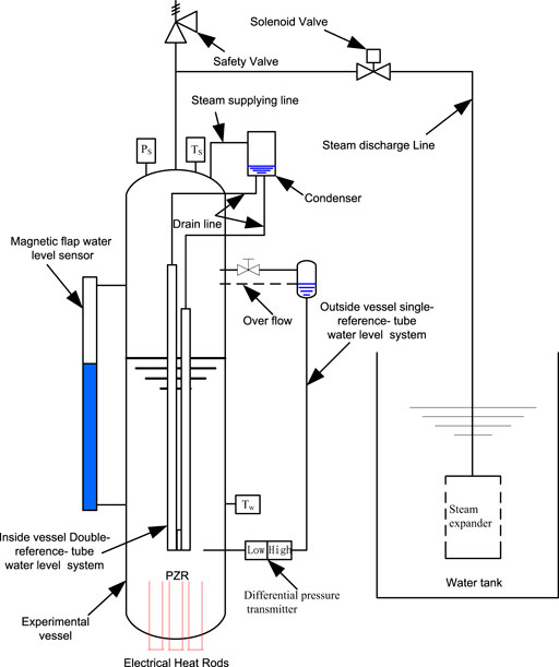
FIGURE 1. Experimental facility.
The experimental vessel has three types of water level measurement systems such as the outside vessel single-reference-tube water level measurement system, the inside vessel double-reference-tube water level system, and the magnetic flap water level sensor with a maximum absolute deviation of 10 mm.
The experimental PZR steam pressure is measured by a sensor with a range of 0–6 MPa and the maximum relative deviation is 0.075%. The pressure differences used by the outside vessel single-reference-tube and inside vessel double-reference-tube water level systems are measured by the sensors with a range of 0–30kPa and a maximum relative deviation of 0.075%. The temperatures are measured by the K-type thermocouples with a maximum absolute deviation of ±1.5°C.
2.2 Outside Vessel Single-Reference-Tube Water Level System
The outside vessel single-reference-tube water level system is shown in Figure 2. On one side, the differential pressure transmitter is connected to the lower section of the vessel. On the other side, it is connected to a capillary reference tube. At the upper end of the reference tube, there is a condenser connected with the PZR steam zone, and the overflow pipe is arranged between the condenser and vessel to maintain the water level in the reference tube.
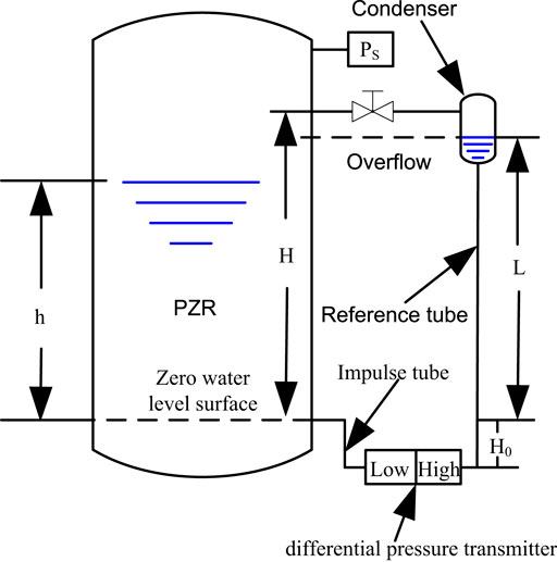
FIGURE 2. Outside vessel single-reference-tube water level system.
The pressure balance of the outside vessel single-reference-tube water level system can be built up through Eq. 1 as follows:
where
The signals of the differential pressure transmitter will be collected into the data acquisition system and transferred into the pressure difference by Eq. (2),
where
By combining Eq. 1 and Eq. 2, the relationship between the water level h and the medium density in the experimental vessel can be expressed as
The medium density in the pressure vessel is assumed to be saturated according to the pressure. That is to say, the water level h in Eq. 3 is a collapsed water level.
2.3 Inside Vessel Double-Reference-Tube Water Level System
The scheme of the inside vessel double-reference-tube water level system is shown in Figure 3. Tube A is the water level measure tube. Tubes B and C are arranged with fixed height differences named the high reference tube and low reference tube. At the outside of the experimental vessel, there is a condenser linked with the steam section. The steam in the condenser will be condensed into water by heat transfer with the environment. The water in the condenser drains into the cistern of reference tubes A and B to maintain the water levels of these two tubes. The inner diameter of the reference tube is 8 mm with a 1 mm thickness. Thermal properties in the two reference tubes will have almost the same thermal properties in the axial direction due to the small thermal inertia.
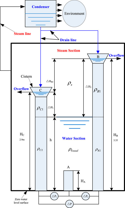
FIGURE 3. Scheme of inside vessel double-reference-tube water level system.
The pressure differences between tubes can be calculated by the following equations:
where
Eq. 6 represents the pressure difference between tubes B and C,
where
From Eqs 4–6, the water level h can be deduced as follows:
Eqs. 7–9 represent how the water level h of the double-reference-tube water level system can be calculated by the structure parameters and the outputs of the differential pressure transmitter. If the water level is below the top of tube C, h is a wide narrow water level which can be calculated by Eq. 7. If the water level is between the top of tubes C and B, h is a wide range water level, and Eq. 8 will be selected. The double-reference-tube water level system is self-redundancy through Eq. 9 for water level monitoring which can be used to validate the results of Eq. 7 or Eq. 8.
2.4 Magnetic Flap Water Level Sensor
The measurement range of the magnetic flap water level sensor used in this test facility is 1.2 m, and the maximum absolute deviation is 10 mm, so the maximum relative deviation is 0.83%.
2.5 Experimental Conditions
The initial experimental conditions for the depressurization are listed in Table 1. The depressurization rates are controlled by the opening of different steam discharge lines.
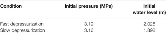
TABLE 1. Experimental conditions.
3 Experimental Results Discussion
3.1 Fast Depressurization
In the fast depressurization case, the initial water level is 2.025 m and the pressure is 3.19 MPa. At 10 s before the depressurization, the electrical power is kept at 15 KW until the end of the transient. The solenoid valve on 15 mm steam discharge line is opened at 217 s and closed at 300 s. Figure 4 shows the trends of the pressure in the experimental vessel. At the time of steam discharge, the pressure of the experimental vessel descends linearly and increases at the end of the depressurization transient according to the electrical power.

FIGURE 4. Vessel pressure of the fast depressurization.
To balance the heat dissipation between the experimental vessel and the environment, the electrical power is needed. There will be some vapor bubbles in the liquid pool. Thus, there are two types of water levels (see Figure 5) named as swollen water level (the mixture of vapor bubbles and liquid water) and collapsed water level (only liquid water).
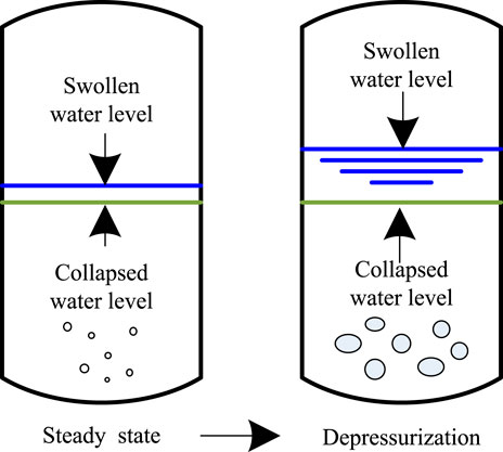
FIGURE 5. Swollen and collapsed levels in the vessel.
Figure 6 shows the trends of the steam and water in comparison with the saturated temperature according to the vessel pressure. Because of the vapor bubbles in the water zone, the output of the double-reference-tube water level system is a swollen water level which is higher than the collapsed one.
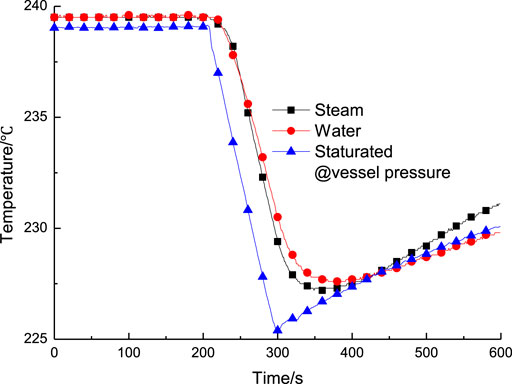
FIGURE 6. Vessel content temperatures of the fast depressurization.
According to the pressure trends in the experimental vessel, the test can be divided into three stages namely; steady, depressurization, and heat up. In the stead state stage, the relative deviations of the water level are 0.94 and 2.34%, respectively, based on the benchmark water level from the magnetic flap sensor (see Figure 7). Since the outside of the magnetic flap water level sensor has no thermal insulation, the water inside is colder than the experimental vessel. The value of the water level in the magnetic flap water level sensor will be a little lower than the actual level. Taking the relative deviations of the magnetic flap water level sensor into account, the water level of the single-reference-tube is in good agreement with the magnetic flap water level sensor. The relative deviation between double-reference-tube and single-reference-tube is about 1.4%.
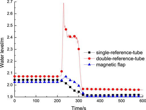
FIGURE 7. Water levels of fast depressurization.
In the stage of depressurization, the water level of the double-reference-tube system is significantly higher than the other two due to the huge vapor bubbles generated in the water zone. In the stage of heat up, the water levels of the single-reference tube and magnetic flap are at the same calibration, which is lower than that in the double-reference tube. The swollen water level has a fixed difference with the collapsed one.
Figure 8 shows the performance of the three channels in the double-reference-tube water system. Eqs. 7–9 represent how the water level h is mainly affected by the structure parameters and the differential pressure transmitters. The peak water levels from Eqs. 7, 9 are higher than those from Eq. 8 at the beginning of the depressurization. In the depressurization stage, the water levels in the two cisterns and the thermal properties in the two reference tubes have randomness differences.

FIGURE 8. Three channels of fast depressurization.
3.2 Slow Depressurization
In the slow depressurization case, the solenoid valve on 8 mm steam discharge line is opened at 255 s and closed at 523 s with 268 s of steam discharge. Figure 9 shows the trends of the pressure in the experimental vessel. The pressure of experimental vessel descends linearly with the steam discharge and rises at the end of the transient by the electrical power.
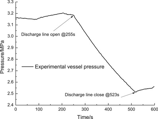
FIGURE 9. Vessel pressure of slow depressurization.
Figure 10 shows the trends of the water levels from the three water level systems which are similar to the fast depressurization test. In comparison with the fast depressurization test, the outputs of the magnetic flap water level sensor are discontinuous.
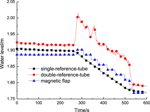
FIGURE 10. Water levels of slow depressurization.
Figure 11 shows the performances of the three channels in the double-reference-tube water system. In comparison with the fast depressurization, the three channels in the double-reference-tube water system are in good agreement with each other.
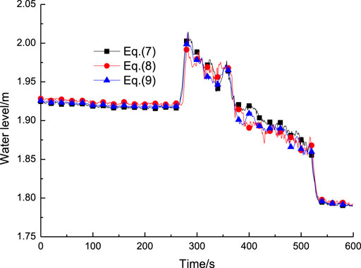
FIGURE 11. Three channels of slow depressurization.
3.3 Analysis of the Engineering Application
For the current PWR, the outside vessel single-reference-tube water level system is selected to monitor and control the PZR water level. In the transient of depressurization, the output water level is lower than the actual level resulting in being partially conservative for safety. For the calculation of the leak rate from the reactor coolant pressure boundary using the PZR water level, the swollen water level will be higher than the actual level which has an adverse effect on the leak rate evaluation. Taken together, the outside vessel single-reference-tube water level system used in the current PZR is adequate for both safety and operation.
For SG in PWR, the cyclone separator and drier are arranged in the direction of steam flow to ensure the steam humidity under the standard requirement. The water level which is too low will lead to the destruction of the water cycle, and the water level which is too high will lead to the steam humidity exceeding the standard requirement. During the transient of depressurization, the swollen water level may be higher than the top of the primary separator (cyclone separator) or above the bottom of the secondary separator (drier) (see Figure 12) which will cause the steam humidity to exceed the standard requirement. In this view, the outside vessel single-reference-tube water level system is unconservative for safety. Thus, the inside vessel double-reference-tube water level system is the best design to monitor the swollen water level in SG, which is helpful for the safety and operation.
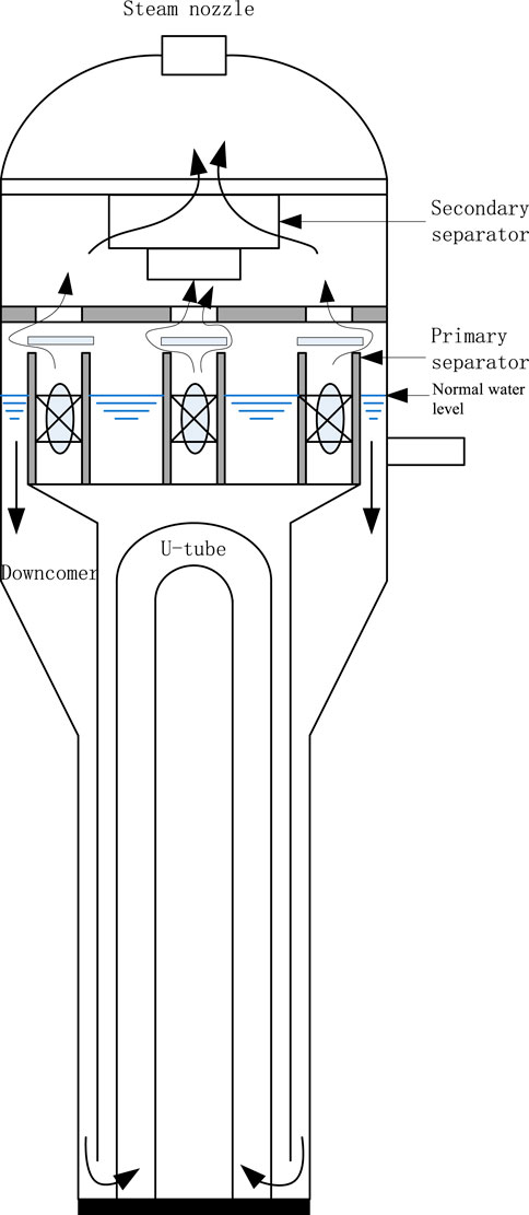
FIGURE 12. Secondary side structures of U tube SG.
Conclusion
The characteristics of high pressure vessel water level measurement at the transients of depressurization have been studied. Significant performances are observed for both steady state and transient. According to the analysis, the following conclusions can be drawn:
(1) The inside vessel double-reference-tube water level system could indicate the swollen water level.
(2) The swollen and collapsed levels have a relatively fixed difference for both high and low depressurization rates.
(3) The outside vessel single-reference-tube water level system used in the current PZR is adequate for both safety and operation.
(4) The inside vessel double-reference-tube water level system is suggested as an additional reference to monitor the water level in SG.
Data Availability Statement
The raw data supporting the conclusions of this article will be made available by the authors, without undue reservation.
Author Contributions
MW designed and carried out the experiments; WC and GF assisted with the data analysis and the manuscript writing.
Conflict of Interest
The authors declare that the research was conducted in the absence of any commercial or financial relationships that could be construed as a potential conflict of interest.
Acknowledgments
Help from Y-XW and Y-W of the Research Institute of Nuclear Power Operation is gratefully acknowledged.
References
Anderson, R. L. (1980). State-of-the art for liquid-level measurements applied to in-vessel coolant level for nuclear reactors. Oak Ridge, Tennessee: Instrumentation and Controls Division Oak Ridge National Laboratory, 12.
Boesmans, B., and Berghmans, J. (1995). Level swell in pool boiling with liquid circulation. Int. J. Heat Mass Tran. 38, 989–998. doi:10.1016/0017-9310(94)00232-K
Boesmans, B., and Berghmans, J. (1996). Modelling boiling delay and transient level swell during emergency pressure relief of liquefied gases. J. Hazard Mater. 46, 93–104. doi:10.1016/0304-3894(95)00061-5
Chen, W. Z., Yu, L., and Hao, J. L. (2013). Thermal hydraulics of nuclear power plants. Beijing, China: Chinese Atomic Energy Press, 100–109. [in Chinese, with English summary].
Chen, W. Z., Zhang, L. M., and Xiao, H. G. (2019). Principles of nuclear reactor engineering. Beijing, China: Chinese Atomic Energy Press, 35–52. [in Chinese, with English summary].
Hardy, P. G., and Richter, H. J. (1986). Pressure transient and two-phase swelling due to a small top break. Nucl. Eng. Des. 95, 207–220. doi:10.1016/0029-5493(86)90048-8
Hatamura, Y., Abe, S., Fuchigami, M., Kasahara, N., and Iino, K. (2014). The 2011 fukushima nuclear power plant accident: how and why it happened. Woodhead Publishing, 220.
Kmetyk, L. N. (1994). MELCOR1.8.3 assessment: GE large vessel blowdown and level swell experiments. Los Alamos, NM: Sandia National Laboratory, 102.
Lin, J. (1986). The measurement of level of marine high temperature and high pressure vessel. Nucl. Power Eng. 7, 65–71 [in Chinese, with English summary].
Maslovaric, B., Blazenka, , Stevanovic, V. D., and Milivojevic, S. (2014). Numerical simulation of two-dimensional kettle reboiler shell side thermal–hydraulics with swell level and liquid mass inventory prediction. Int. J. Heat Mass Tran. 75, 109–121. doi:10.1016/j.ijheatmasstransfer.2014.03.064
Riznic, J. (2017). Steam generators for nuclear power plants. Ottawa, Canada: Woodhead Publishing, 578.
Sanda, R. M., and Veira, M. P. (2014). European clearinghouse: report on leaks and cracks of reactor coolant pressure boundary. Luxembourg: Join Research Center, 6–15.
Schulz, T. L. (2006). Westinghouse AP1000 advanced passive plant. Nucl. Eng. Des. 236, 1547–1557. doi:10.1016/j.nucengdes.2006.03.049
Shah, V. N. (1998). INEEL/EXT-97-01068. Assessment of pressurized water reactor primary system leaks. Available at: https://catalogue.nla.gov.au/Record/ (Accessed December 1998).
Keywords: high pressure vessel, swollen water level, collapsed water level, transient, experimental study
Citation: Wang M, Chen W and Fan G (2021) Investigation on Transient Characteristics of High Pressure Vessel Water Level Measurement. Front. Energy Res. 9:609320. doi: 10.3389/fenrg.2021.609320
Received: 23 September 2020; Accepted: 14 January 2021;
Published: 25 February 2021.
Edited by:
Jun Wang, University of Wisconsin-Madison, United StatesReviewed by:
Jiang Lai, Nuclear Power Institute of China (NPIC), ChinaLuteng Zhang, Chongqing University, China
Copyright © 2021 Wang, Chen and Fan. This is an open-access article distributed under the terms of the Creative Commons Attribution License (CC BY). The use, distribution or reproduction in other forums is permitted, provided the original author(s) and the copyright owner(s) are credited and that the original publication in this journal is cited, in accordance with accepted academic practice. No use, distribution or reproduction is permitted which does not comply with these terms.
*Correspondence: Guangming Fan, ZmFuZ3VhbmdtaW5nQGhyYmV1LmVkdS5jbg==