 Zheng Dang
 Zhaoyi Jiang2
 Xin Shen
- 1Department of Fluid Machinery and Engineering, School of Energy and Power Engineering, Xi’an Jiaotong University, Xi’an, China
- 2Department of Civil Engineering, School of Human Settlement and Civil Engineering, Xi’an Jiaotong University, Xi’an, China
In order to solve the environmental pollution problem caused by winter heating of rural residential building in northern of China, in this paper a biomass gasification (BG)-solid oxide fuel cell (SOFC) combined heat and power (CHP) system has been establishedand numerically investigated. Taking a rural village around Xi’an which is an ancient city and located at central of northern China as the study object, according to heat and electricity output of the system and the heating and electrical load characteristics of the residential building of village, the energy saving ratio and economical efficiency of the CHP system under three different operation schemes compared with the traditional energy system have been analyzed. The results show that the operation scheme for heating designated rooms in rural buildings and meeting the average heat demand of users is the most energy-efficient and economical way. The primary energy saving rate and annual cost saving rate can reach 18.0% and 10.3%, respectively. When the user’s heat and power load demand is clear, the closer the system’s output heat and power ratio to the user’s heat and power load ratio, the more significant the system’s energy saving effect.
Introduction
With the intensification of global warming trends, increasing pressure on environmental protection, and the increasing scarcity of fossil energy sources, the use of renewable energy is becoming more and more popular in the world, which has become one of the promising energy sources supporting the sustainable development of human society. At present, there is generally no advanced heating technology in rural of China. So far, distributed burning of coal is the main heating method for rural residential building, which has caused severe environmental pollution problems. For rural or remote places of northern of China, where buildings are not concentrated and traditional energy supply method for building is inefficient, therefore it is urgent to find an efficient and clean space heating techniques for this kind of rural buildings. On the other hand, there are a lot of biomass resources (mainly straw) in northern China, after the harvesting of crops how to deal with a large amount of straw become a big problem. In the past years, straw is often burning in the field, but now it is forbidden by the government because of the heavy air pollution. As we know, straw is a kind of biomass and biomass energy is a form of renewable energy. Generally, biomass energy is gotten through photosynthesis of plants by which solar energy is converted into chemical energy and stored in the body of biomass. Based on the heating technology needs in rural of northern of China, it is very important to seek to use straw as fuel for heating system development (Chen and Zhu, 2018; Yan et al., 2020).
Zhou et al. (2019) built a system of combined heating of solar energy and biomass energy with rural housing as a platform, and compared it with solar energy and auxiliary electric heating system to get good comfort and energy saving of the system. Zhang et al. (2017) built a biogas-based internal combustion engine CHP system, combined with rural user-side demand and supplemental heat sources, established a full-operation dynamic mathematical model, and conducted daily energy supply and demand balance analysis of the system throughout the year. The results show that the primary energy utilization rate of the system is 37.58%, compared with the traditional system, the primary energy saving rate is 17.12%. Li Y. et al. (2015) established a micro gas turbine CHP system, and analyzed the impact of the user’s heat to power ratio (TER) and grid power purchase ratio on the energy saving potential of the CHP under the condition that the unit matched the user’s load. The energy saving rate can reach 22.76%∼23.16%. Cong et al. (2018) analyzed the feasibility of applying biomass pyrolysis cogeneration technology in rural areas. The results show that the cogeneration technology is suitable for small central heating of about 200 households. The initial investment is generally not more than 3 million yuan, the investment recovery period is 4–5 years. Li G. et al. (2015) proposed a heating system based on a biomass particles forming fuel furnace, and compared with the traditional kang heating system. The results show that the heating effect of this system is better under intermittent heating conditions. Chen et al. (2014) used technical and economical analysis methods to compare two schemes for centralized heating and household heating of BG in a rural suburb of Tianjin, and gave the heating optimization plan for the village. Zhou et al. (2014) conducted an economical and environmental benefit analysis of the rural BG decentralized heating technology. The results show that the heating costs can be reduced to a reasonable level by means of segmented temperature control, temperature control in separate rooms, and energy-saving building renovation. From the above review of previous researches it can be concluded that, in northern of China, the utilization of rural biomass resources mainly includes the conversion of other biomass products into related energy products, direct combustion to provide heat, and combined use as fuel of cogeneration system. Among them, the development and utilization of biomass cogeneration technology has gradually become the main trend. However, in these works, heat engines are still used as the prime mover with exhaust pollution induced by burning.
Fortunately SOFC is a kind of device which can convert the chemical energy of fuel into electricity directly by electrochemical reaction and without burning process. If hydrogen is used as fuel the exhaust of SOFC is just water. If hydrocarbons including biomass are reformed, desulfurized, and fed as fuel, the exhaust of SOFC will still has zero oxynitride. Therefore SOFC is relatively more efficient, environmentally friendly than traditional burning system. In general straw can be used as a fuel for SOFC operation after a gasification and reforming process to construct rural building combined heat and power generation systems.
Different biomass raw materials and gasification gas production under different conditions will affect the performance of SOFC. Dey et al. (2014) studied the influence of different types of biomass raw materials on the BG-SOFC system, and the results showed that bagasse showed the best performance in the mixed system. Amiri et al. (2018) simulated the impact of fuel changes on the performance of the co-generation system by considering various fuel sources (such as natural gas, biogas, and syngas). The results show that fuel changes may seriously affect the consistency of the overall performance index of the system. All ideal results are obtained with a single fuel, so progressive multivariate and multi-objective optimization is required. Wan (2016) by integrating the gasification unit with the supercritical water unit to produce clean syngas for SOFC, the integrated system can achieve a power generation efficiency of 46.3%. Palomba et al. (2017) proposed a 630 kWh lignocellulose gasification solid oxide fuel cell cogeneration system simulation model. The results show that the primary energy consumption of the cogeneration system can be reduced by about 15 GW ⋅ H/y, CO2 emission reduction is about 5,000 t/y. Jia et al. (2015) conducted energy analysis of the integration process of biomass gasification and SOFC, and gave a performance comparison of power systems for different gasification agents through thermodynamic method. The results show that when oxygen-enriched air is used as the gasification agent, the gasifier has the largest loss, and the total efficiency of the cogeneration is 29%. When steam is used as the gasification agent, the heat exchanger has the largest loss. The net electrical efficiency and efficiency of the system are 40 and 36%, respectively, which are higher than the efficiency when using oxygen-enriched air as the gasifying agent. Giarola et al. (2018) studied the energy efficiency indicators and economic performance of wastewater treatment facilities equipped with SOFC-CHP devices. Compared with traditional alternatives, they developed an optimization framework. The results show that both investment costs and operating costs of the combined supply system used in wastewater treatment plants are reduced. Rokni (2018) proposed a solid oxide fuel cell absorption refrigeration tri-generation system based on municipal waste gasification. The system can maintain itself and does not need to rely on the grid for district heating and cooling. The results show that its system energy efficiency has exceeded 83%.
The researches in above literatures showed that SOFC has high power generation efficiency and can be accompanied by high-quality waste heat. As a prime mover of the distributed multi-supply system, it can effectively improve the efficiency of energy use and reduce energy consumption. At the same time, due to its higher operating temperature, hydrocarbon can be used as fuel, so they have a wide range of fuel adaptability. However, most of the researches are only focused on the performance and optimization of the SOFC-CHP system itself, but scarce work has been done to consider the characteristic of the heat and electrical load of particular building especially for the rural residential building of northern of China. Therefore, based on the actual demand situation in rural of northern of China, this paper designs and determines a BG-SOFC-CHP with a power generation of 100 kW for rural residential building around Xi’an City. Combining the heat and electricity output of the system and the heat and power load characteristics of rural buildings, analyze the advantages of this CHP system in terms of energy saving and economy compared to the traditional energy system under three different operating schemes. The results and conclusion will benefit the development of clean and efficient space heating techniques of rural residential building for northern of China.
System Construction
System Model
Figure 1 shows the flowchart of the CHP system. The system mainly includes two parts: the biomass gasification part and the solid oxide fuel cell part. First of all, for the biomass gasification module, biomass is pyrolyzed and gasified to generate combustible gas, which is used as fuel to be introduced into the anode of SOFC. Since the operating pressure of the biomass gasification process is much greater than that of the solid oxide fuel cell, the produced gas is purified by desulfurization and other purification treatments and then decompressed through an expander. The outlet pressure of the expander is set to be consistent with the operating pressure of SOFC. Heat required for the gasification process is completely provided by the burner after SOFC stack. For the SOFC part, the gasification gas is mixed with the water pressurized by the water pump, and then is heated to the required inlet temperature of the SOFC by the hot exhaust gas from the burner. After being pressurized, air is also heated by the hot exhaust gas from the burner. Finally fuel and air are fed into anode and cathode of SOFC for electrochemical reaction to generate electricity. After two heat exchangers, the exhaust gas still has a relatively high temperature, and this part of the heat is recovered to provide space heating and hot water for living.
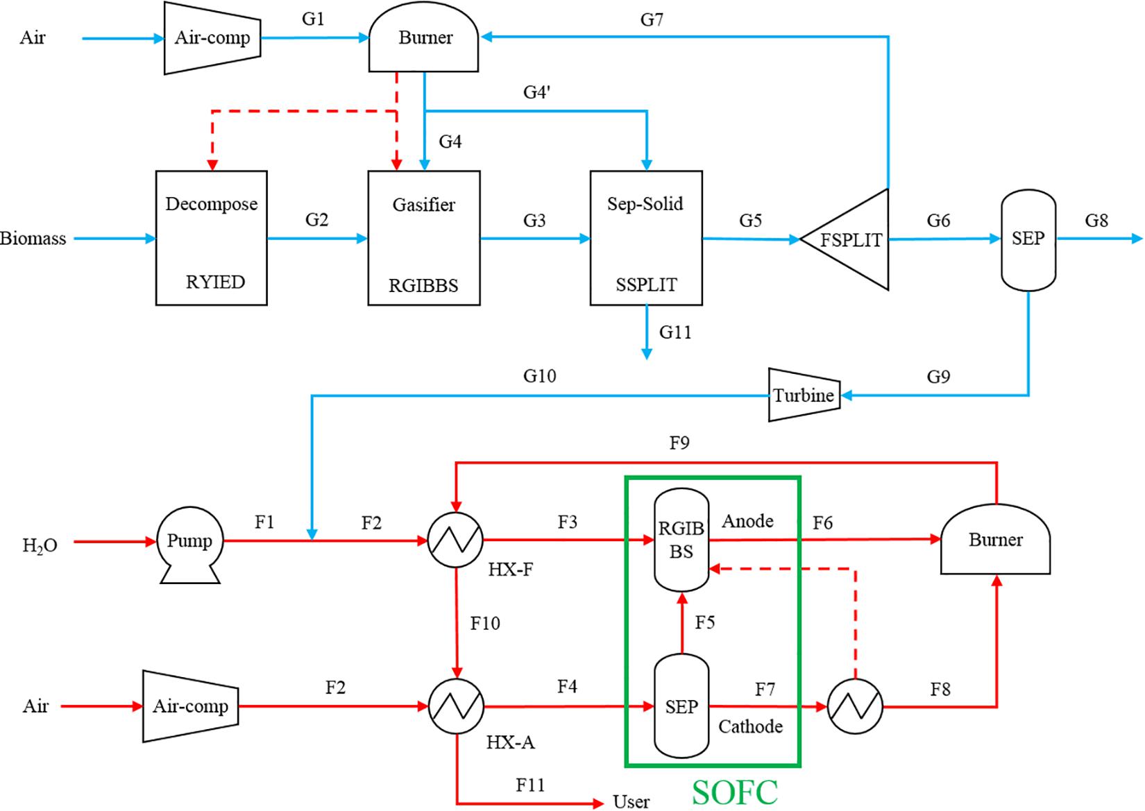
Figure 1. BG-SOFC-CHP system flowchart. F, fuel; G, gas; HX, heat exchanger; SEP, separator; COMP, compressor; RGIBBS, Gibbs reactor.
Chemical and Electrochemical Model
The fuel is natural gas, chemical reactions mainly include methane reforming and shift reaction as follows:
Because the rate of the oxidation reaction of carbon monoxide is much slower than that of the water vapor shift reaction, therefore, the oxidation reaction of carbon monoxide is ignored in the present research. The electrochemical reactions occurring at the anode and cathode of the SOFC are as follows:
Anode:
Cathode:
Total chemical reaction:
For the methane reforming reaction rate, the Achenbach model is used to describe it (Achenbach, 1994):
Here: kCH4—reaction rate coefficient of CH4/kJ⋅mol–1; PCH4—partial pressure of CH4/bar;.ECH4—activation energy of CH4/mol⋅m–2⋅bar–1⋅s–1.
For the water vapor shift reaction, because of its fast reaction rate, it can be considered that it reaches equilibrium quickly, and the equilibrium constant satisfies:
Here: nx—molar flow rate of component x/mol⋅s–1; R—Gas mole constant/J⋅mol–1⋅K–1; T—Gas temperature/K.
Assuming that there is no volume change work during the electrochemical reaction process, that is, all the energy released by the chemical reaction is output in the form of electrical work, the maximum output work is equal to the Gibbs free energy change of the chemical reaction, which can be expressed as follows:
Here: ΔG—Gibss free energy change of total cell reaction/W; ne—The number of electrons transferred in a electrochemical reaction; F—Faraday constant/96485C⋅mol–1; EN—Nernst electromotive force/V.
Put into the cell reaction Eq. 5, the Nernst electromotive force can be expressed as:
Here: ΔG—Standard Gibbs Free Enthalpy Change/W; T—Reaction temperature/K; R—Universal gas constant/8.314J⋅mol–1⋅K–1; Pi—Partial pressure of each component/bar.
The current of the SOFC can be expressed as:
Here: nH2,consume—The equivalent amount of hydrogen consumed/mol⋅s–1.
The current density of the SOFC can be expressed as:
Here: A—Effective area of cell unit/m2.
The output power can be expressed as:
Here: Vcell—Output voltage of fuel cell/V.
Loss Model
The voltage loss of SOFC mainly includes ohmic loss, activation loss and concentration loss. The ohmic loss is caused by the resistance of each component when the current flows through the components of the cell unit; the activation loss is caused by the lag of the electrochemical reaction on the electrode surface; the concentration loss is caused by the pressure drop on the porous electrodes. Considering that the concentration loss mainly plays a significant role under the high current density, and this research mainly focuses on the normal current density, the influence of the concentration loss is ignored in this paper. The final output voltage of the SOFCcan be expressed as follows:
Here: Ract,a—Equivalent activation resistance of anode/Ω⋅m2; Ract,c—The equivalent activation resistance of the cathode/Ω⋅m2.
The calculation of cell ohmic loss can be expressed as follows:
Here: ρi—Resistivity/Ω⋅m; δi—Electrode thickness/m; S—Effective area of cell/m2; σi—Conductivity/Ω–1⋅m–1, The conductivity calculation formula of each component is shown in Table 1.
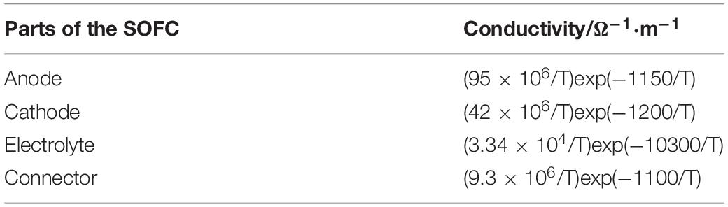
Table 1. Conductivity of SOFC components (Braun, 2002).
The calculation of activation loss refers to Achenbach’s model, which is expressed as follows:
Here: kA—Activation coefficient of anode/A⋅m2; kC—Activation coefficient of cathode/A⋅m2; EA—Activation energy of anode/kJ⋅mol–1; EC—Activation energy of cathode/kJ⋅mol–1; m—index/0.25.
Mathematical Model of Other Equipments
Compressor, water pump model.
The compressor and water pump pressurize the reactants to reach the pressure required for system operation. In this study, the method of isentropic compression is used. The power consumption of these devices during operation can be calculated by the following formula:
Here: W—Power consumption of equipment/W; n—Polytropic index; T1—Inlet temperature of compressor/K; π—Compression ratio.
Heat exchanger model.
The heat exchanger in this study uses a counter flow heat exchanger, and its thermodynamic calculation model is mainly based on the heat transfer equation and the energy balance equation, expressed as follows:
Heat transfer equation:
Energy balance equation:
Here: Q—Heat flow rate/kW; k—Heat transfer coefficient/W⋅m–2⋅°C–1; A—Heat exchanger area/m2; Δt—Average heat exchange temperature difference/°C; qm1,qm2—Mass flow of cold and hot fluid/kg⋅s–1; c1,c2—specific heat capacity of cold and hot fluid/J⋅kg–1⋅°C–1; t1’,t1”—Inlet and outlet temperature of cold fluid/°C; t2’,t2”—Inlet and outlet temperature of hot fluid/°C.
Burner model.
In the SOFC system, the remaining fuel in the anode outlet and the excess air in the cathode outlet enter the combustion chamber again for full combustion. In this paper, it is assumed that the combustion chamber is under adiabatic conditions with no heat loss, and all remaining fuel in the anode tail gas reacts completely.
In the combustion chamber, the main components that can participate in the reaction are CH4, H2 and CO. The reaction equation of each component is as follows:
According to the mass conservation equation and energy conservation equation, the gas entering and leaving the combustion chamber satisfies the following relationship:
Here: nx,in—The molar flow rate of componentxat the inlet of the combustion chamber/mol⋅ s–1; nx,out—The molar flow rate of componentxat the outlet of the combustion chamber/mol⋅ s–1; Tin—Combustor inlet temperature/K; Tout—Outlet temperature of combustor/K.
Thermal storage tank model.
Rural households use water for periods of time, so the heat load during the day fluctuates. For the time period when the heat load demand is less than the heat produced by the cogeneration system, the heat storage tank is used to store this part of the heat. When the heat supply system is insufficient, the stored heat can be used to make up, and the capacity of the heat storage tank is determined according to the difference between the user’s maximum heat load and the average heat load.
The amount of water in the thermal storage tank satisfies the following relationship:
Here: mt—The amount of water in the thermal storage tank at time t/kg; mt–1—The amount of water contained in the heat storage tank itself/kg; mtCHP—The amount of water produced and stored in the cogeneration system at time t/kg; mtuser—User’s water consumption at time t/kg.
The change of hot water temperature satisfies the following relationship:
Here: m—The quality of hot water/kg; c—Specific heat capacity of hot water/kJ⋅kg–1⋅°C–1; T—The temperature of the hot water/°C; Qr—The heat storage tank absorbs the stored heat/kW; Quser—Heat loss on the user side/kW; Qloss—Heat loss of heat storage tank/kW.
After studying the parameter conditions in the gasification process and the influences of parameter conditions on the SOFC and system performances, based upon the building power load demand, and set the 100 kW system net power generation as the design target, higher system cogeneration efficiency as the goals of system optimization, the design parameters of the biomass gasification solid oxide cogeneration system are finally determined. Table 2 are the results of modeling and parameter optimization using the approach described in the above subsection.
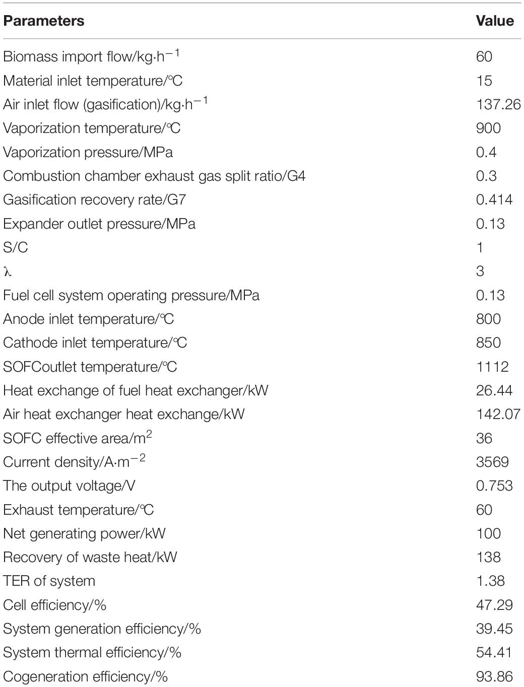
Table 2. 100 kW BG-SOFC-CHP system parameters.
Calculation of Building Load
DeST (Designer’s Simulation Toolkit) is a software platform (Tsinghua University, 2020) for building environment and HVAC system simulation developed by the Department of Building Technology Science, Tsinghua University. This paper uses this software to calculate the annual dynamic load of residential buildings.
This article takes a rural residential building in Xi’an as the research object. The building has two floors and a total area of 171 m2. The DeST simulation software was used to calculate the hourly cooling and heating loads of the residential building throughout the year, and January 21 was selected as a typical winter day to study the hourly load changes of the building during the day. At the same time, the hot water load and electricity load of the building throughout the day are calculated according to the relevant standards in the “Code for Design of Civil Building Electrical Appliances” (JGJ 16-2008) and “Code for Design of Building Water Supply and Drainage,” and the simulation results of the building’s heat and electrical load are shown in Figure 2.
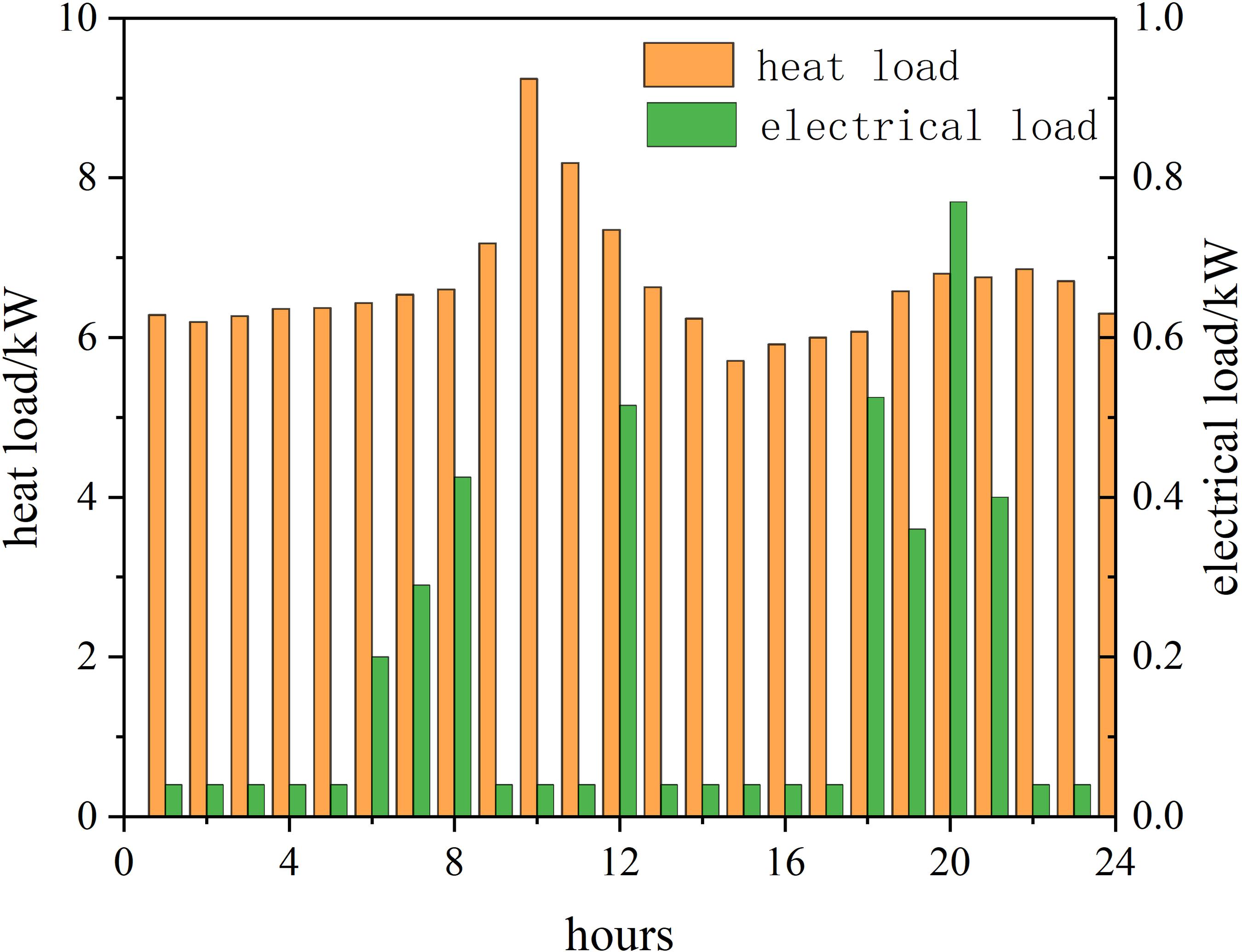
Figure 2. Typical daily heat load and electric load in winter.
System Evaluation Indicators
Primary Energy Saving Ratio (PESR) refers to the amount of primary energy consumed by the cogeneration system compared to the amount of primary energy consumed by the traditional energy supply system when meeting the user’s same thermal and electric load demand. This paper takes PE/PE∗ the ratio of the primary energy consumption PE of the cogeneration system to the primary energy consumption PE∗ of the traditional energy system as the evaluation parameter, and the corresponding primary energy saving rate can be expressed as 1-PE/PE∗. Calculated as follows:
Where: PE∗—total energy consumption of the traditional energy system/kW⋅h; PE∗PP—electric power purchased by the traditional system from the grid/kW⋅h; PE∗B—primary energy consumption of the boiler in the traditional system/kW ⋅h; PE—the total energy consumption of the cogeneration system/kW⋅h; PECHP—the primary energy consumption of the cogeneration system/kW⋅h; PEP—the electricity purchased by the cogeneration system from the grid/kW⋅h; PEB—Primary energy consumption of the boiler in the cogeneration system/kW⋅h; Pel, CHP, sur—grid-connected power of the cogeneration system/kW⋅h; Pth, CHP, sur—storage heat of the cogeneration system/kW⋅h.
Considering that the thermal and electrical output of the system, the user’s heat and electrical load demand cannot be completely matched, there will be a certain deviation, so according to the possible circumstances, the following three cases are discussed:
(1) The power generation and heat output of the combined supply system are used to meet the user’s basic load supply, but do not exceed the user’s electrical load and heat load demand. Combining the above formulas to obtain the primary energy saving rate calculation formula (Pohl and Diarra, 2014a, b):
In the formula: σD—user-side electric heating ratio; σCHP—cogeneration system electric heating ratio; ηth, B—boiler thermal efficiency; ηel, CHP—cogeneration system power generation efficiency; ηel, PP—power generation efficiency of power plant; ΔPel—User side purchases electricity from the grid/kW; Pel,D—User side electrical load/kW⋅h.
(2) The heat output of the combined supply system just meets the heat load demand of the user side, and the power generation capacity is surplus. Combining the above formulas to obtain the primary energy saving rate calculation formula:
(3)The power generation of the combined supply system just meets the electric load demand of the user side, and the heat production has surplus. Combining the above formulas to obtain the primary energy saving rate calculation formula:
The annual cost rate reflects the economy of the joint supply system compared to the traditional system, and its expression is as follows (Ehyaei and Rosen, 2019; Sadat et al., 2019) :
CHP System Scheme
Combining the heat and electricity output of the CHP system established in this paper and the heat load and electricity load requirements of residential buildings, this section mainly discusses the energy-saving and economy of the CHP system and the traditional system under different operation schemes.
Scheme One
According to the heat output and electricity output of the system, 20 residential users are used as heating objects. The composition of the user-side heat load and electricity load under this scheme can be obtained as shown in Figures 3, 4, the primary energy saving rate of the system is shown in Figure 5.
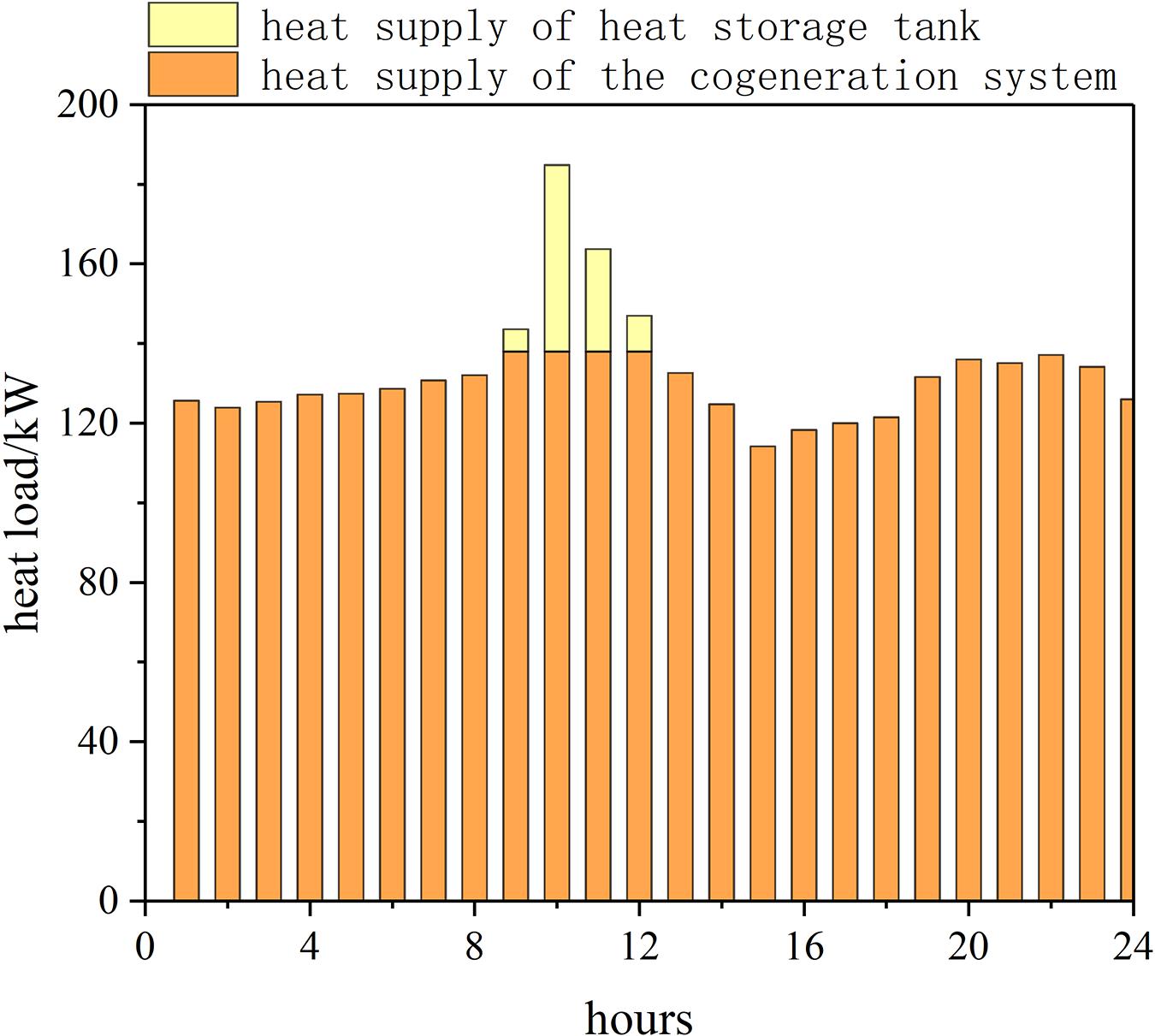
Figure 3. Thermal energy supply on a typical winter day.
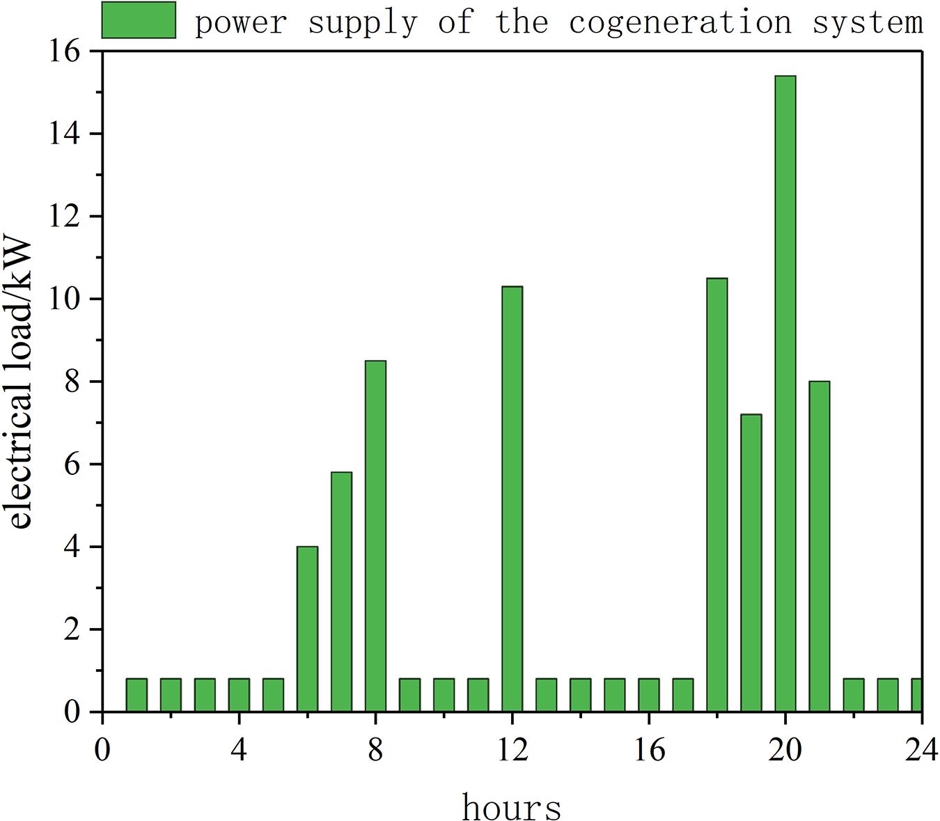
Figure 4. Power supply on a typical winter day.
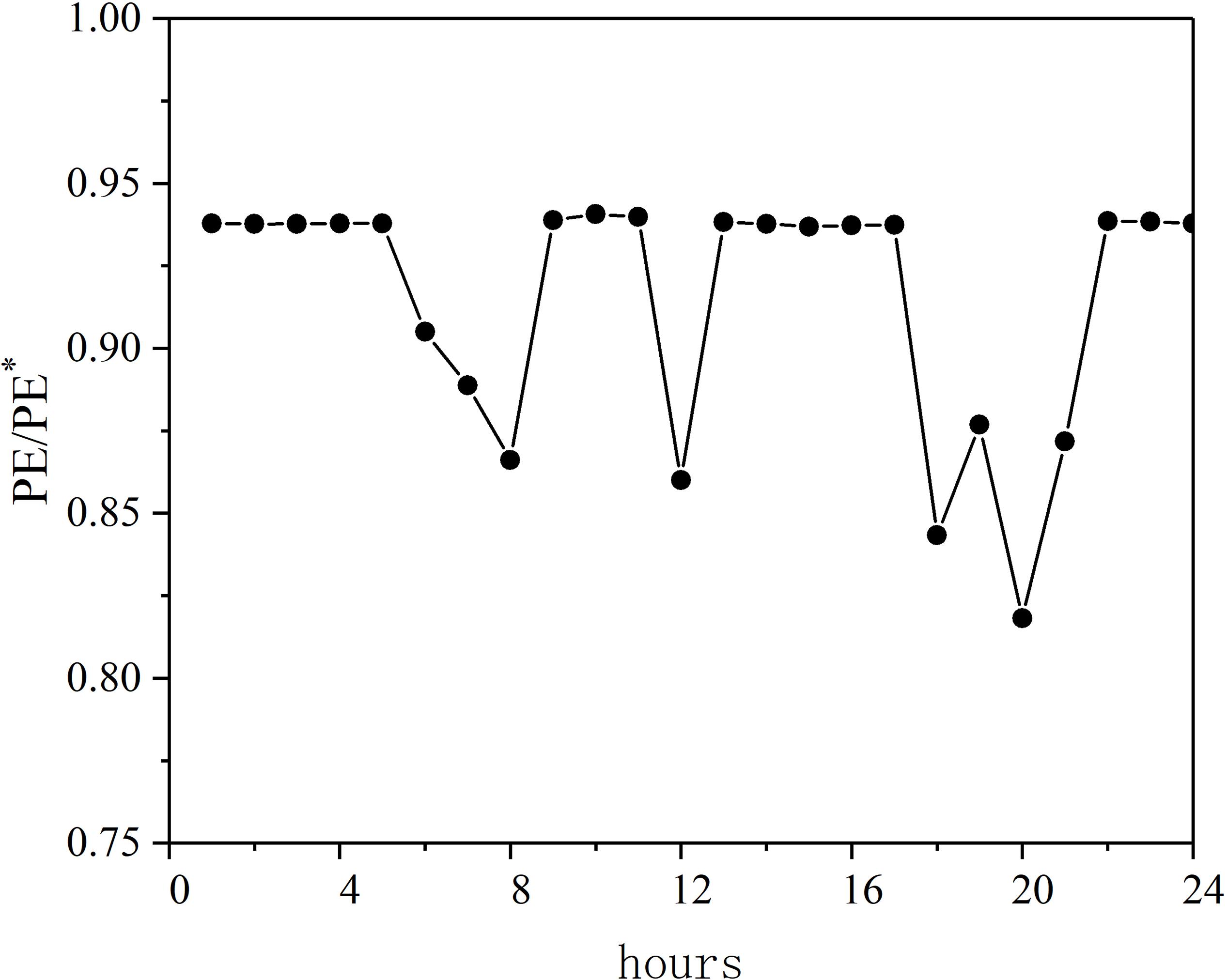
Figure 5. Typical hourly energy consumption ratio in winter.
It can be seen that under this scheme, the power generation of the joint supply system fully meets the user’s electrical load demand, and there is still surplus. The excess power generation is used in the online sales mode. In addition to the large heat load demand of users between 9:00 and 12:00 during the day, the supply of the CHP system is insufficient, and the heat production of the CHP system can meet the user’s heat load requirements in other periods. In this case, the corresponding heat storage tank is configured for the cogeneration supply system, and the excess heat is stored through the heat storage tank. When the heat generated by the system cannot meet the user’s heat load demand, the stored heat is replenished to the user.
The largest values of system’s primary energy saving rate occurred mainly around three periods of morning, noon, and evening, which is basically consistent with the trend of electrical load changes. This is because the user’s electrical load is relatively increased at this time, and the heat load change is very small. The decrease in the heat to electricity ratio TER of user results in more significant energy savings. Compared with the traditional system, the primary energy saving efficiency under this scheme is about 8.6%, and the annual cost saving rate is 5.5%.
Scheme Two
Since the heat load demand of rural houses is much larger than the electricity load demand, according to the heat and power output of the designed 100 kW CHP system, it can only meet the heat demand of a small number of users, and there is a large surplus of power generation in the system. Combining the actual situation of heating in rural buildings in winter and the living habits of rural users, the actual heating area of a building generally includes only a few commonly used rooms, while other rooms are generally idle and there is no need for heating. Therefore, the heating area only selects the living room and master bedroom and secondary bedroom. Similarly, heating is performed in a manner that satisfies the average heat load of users. Combined with the system’s thermal power output, 123 residential users are selected as heating objects, and the user’s heat load, electricity load and the system’s primary energy saving rate are calculated, as shown in Figures 6–8.
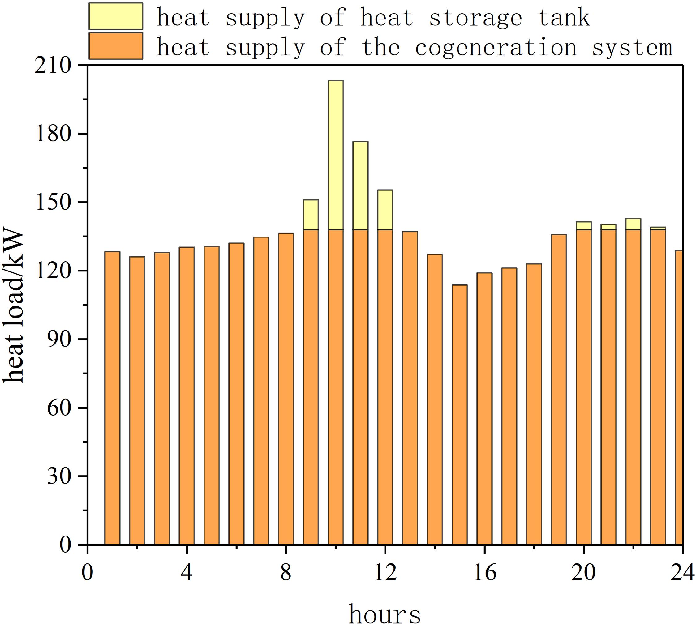
Figure 6. Thermal energy supply on a typical winter day.
As can be seen from the results in the figure, except that the heat output of the CHP system between 9 o’clock and 12 o’clock and between 20 o’clock and 23 o’clock cannot meet the user’s heat load demand, the heat supply of the CHP system can meet the user’s needs at other times. And there is surplus heat. Similarly, it is processed by adding a heat storage tank as in the first scheme. Under this scheme, the change trend of the primary energy saving rate of the CHP system is basically the same as that in Figure 5, but the primary energy saving rate is greater. This is because compared with the first case, at this time the user’s heat load is reduced, the electrical load remains unchanged, and the TER of user decreases, so the energy saving effect is more significant. Compared with the traditional system, the primary energy saving efficiency under this scheme is about 18.0%, and the annual cost saving rate is 10.3%.
Scheme Three
This section is also based on the actual heating situation in the countryside and operates according to the scheme that meets the user’s daily average electrical load demand. The system can meet the average electricity load of the entire village. Figures 9, 10 show the user’s heat and power load during the heating period, and the hourly energy consumption of the CHP system is shown in Figure 11.
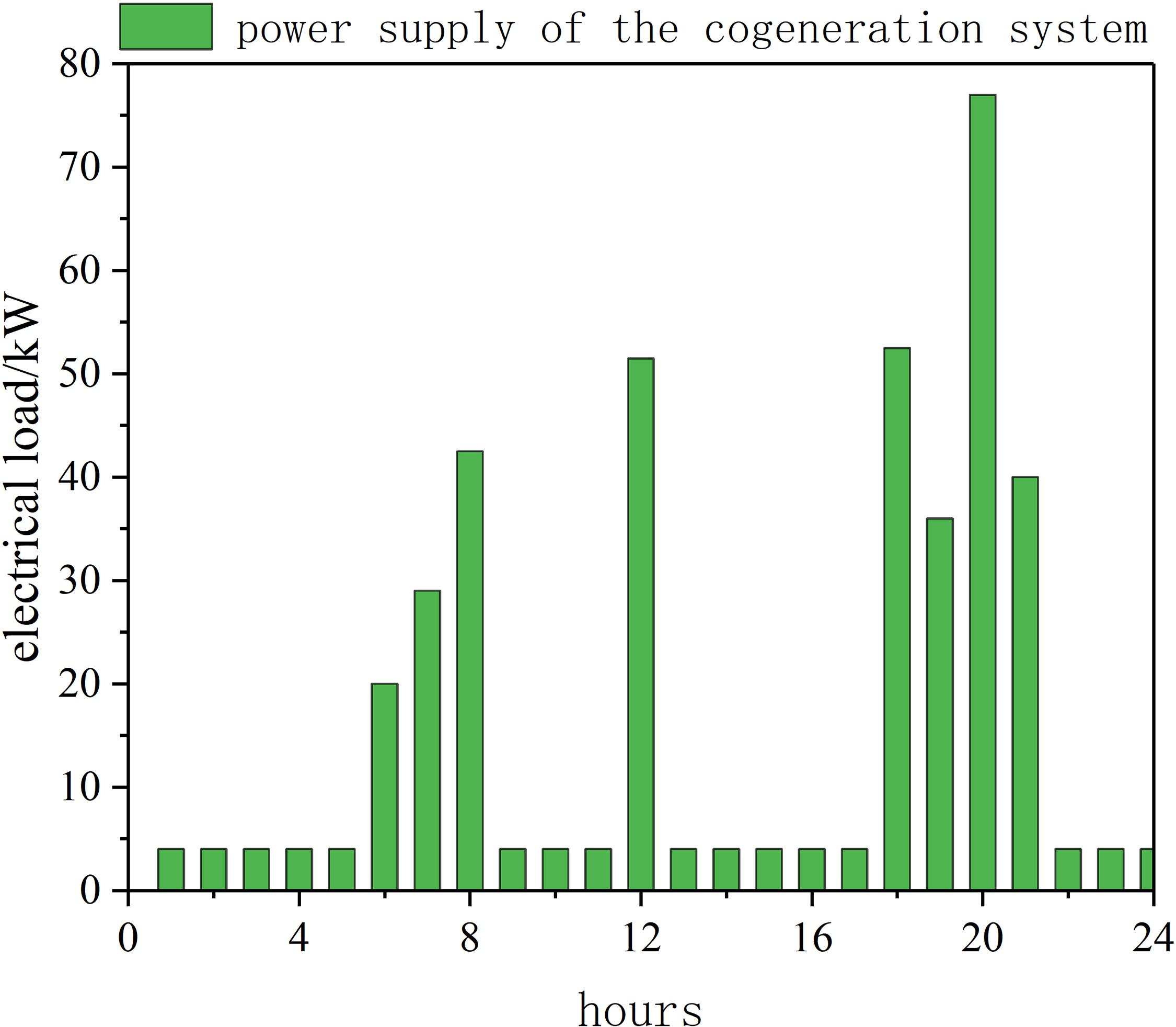
Figure 7. Power supply on a typical winter day.
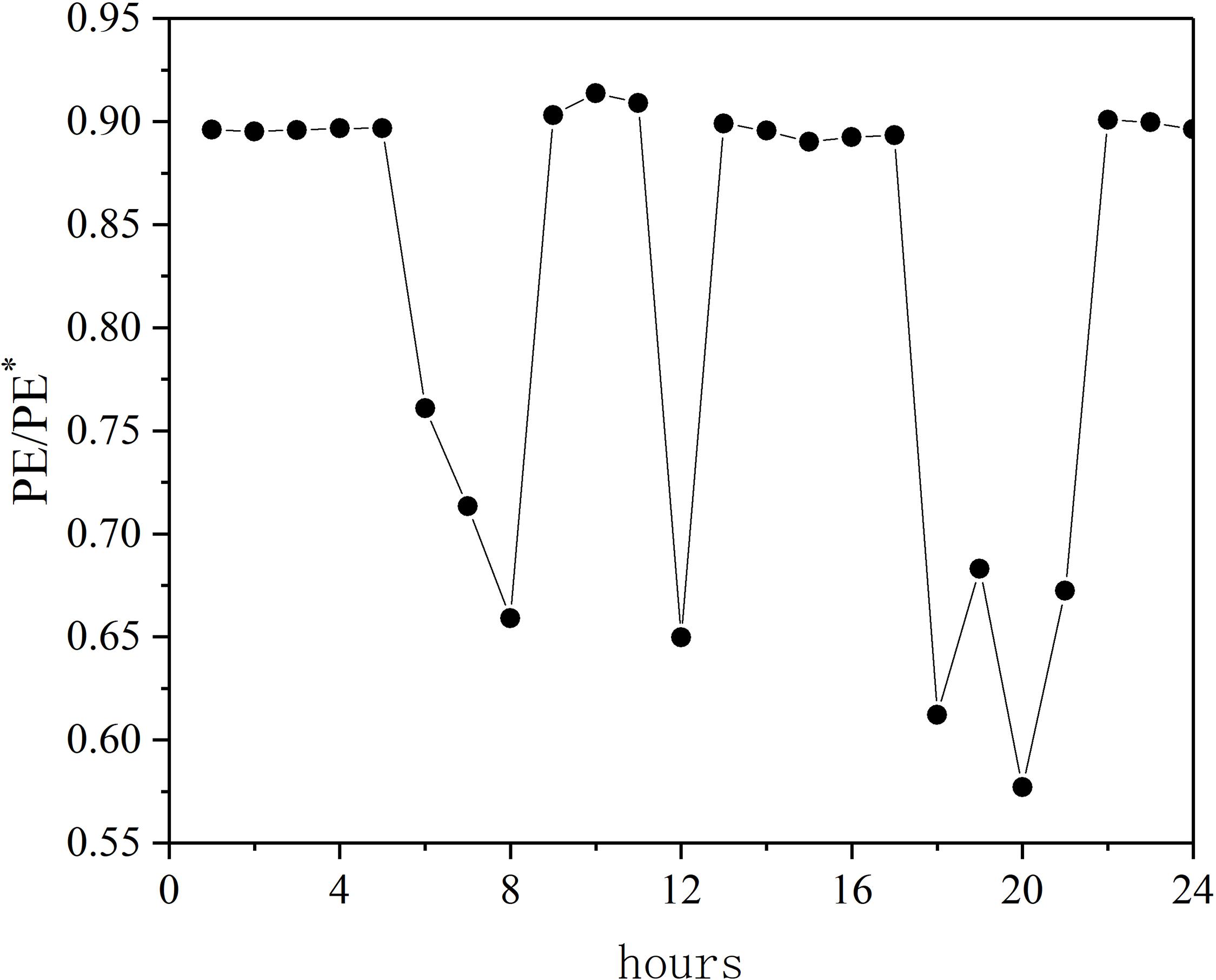
Figure 8. Typical hourly energy consumption ratio in winter.
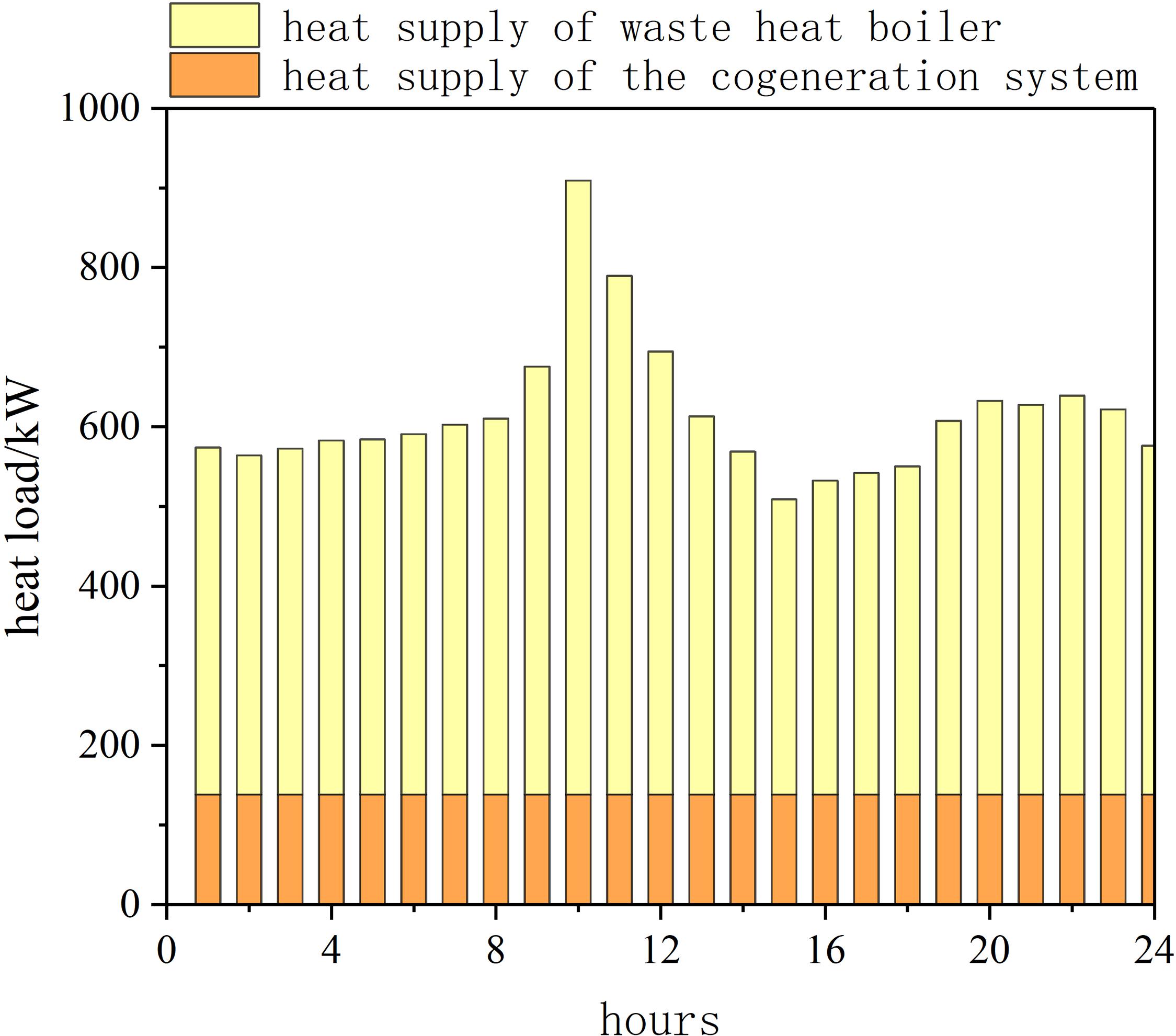
Figure 9. Thermal energy supply on a typical winter day.
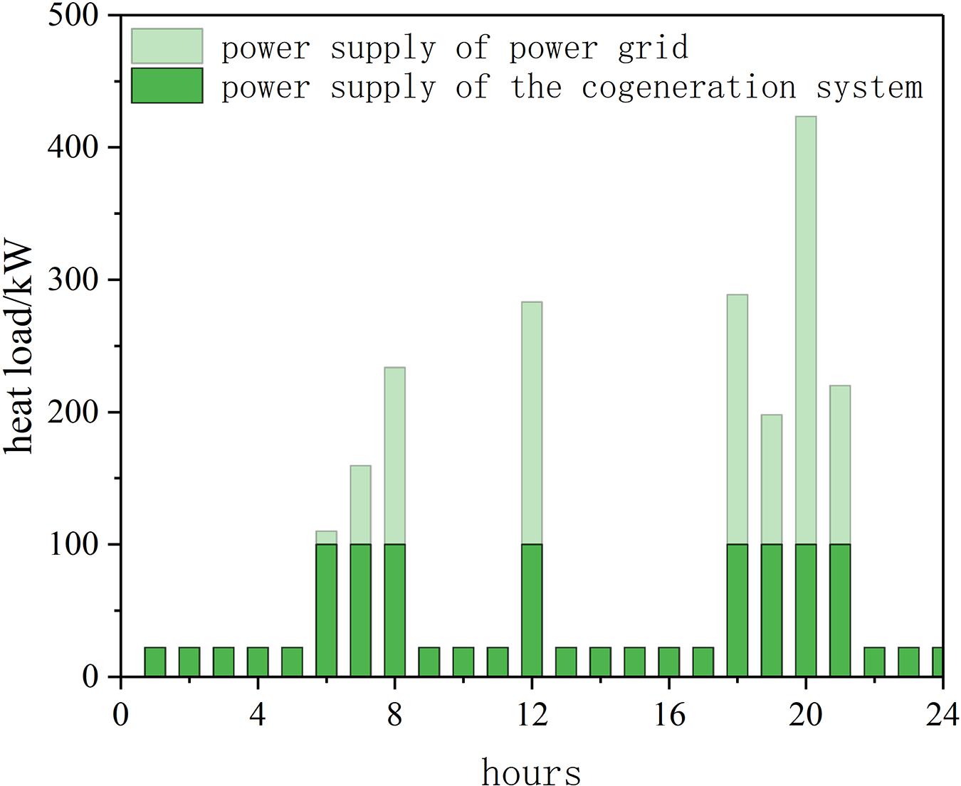
Figure 10. Power supply on a typical winter day.
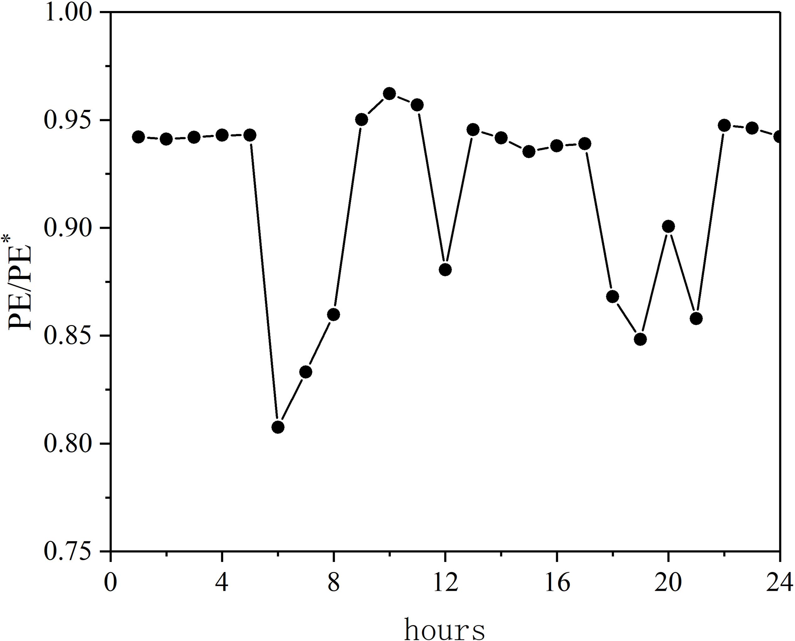
Figure 11. Typical hourly energy consumption ratio in winter.
It can be seen that under this scheme, the heat production of the CHP system can only meet a small part of the user’s heat load demand, and most of the remaining heat load needs to be supplemented by the heat production of the waste heat boiler, in this case, the heat boiler provides heat source for the heat storage tank; except for morning, noon, and evening, the peak electricity consumption needs to be supplemented by purchasing electricity from the power grid. The electricity consumption load for the rest time is fully borne by the CHP system, and the excess power generation is sold online. The primary energy saving rate of the system is about 8.5%, and the annual cost saving rate of the system is about −20.2%.
CHP System Regulation
According to the analysis in Section “System Evaluation Indicators,” the primary energy saving rate of the system is mainly related with the heat to electricity ratio on the user side. The relationship between the hourly energy consumption ratio of the CHP system and the user’s TER has been discussed for the first and second operating modes, as shown in Figure 12.
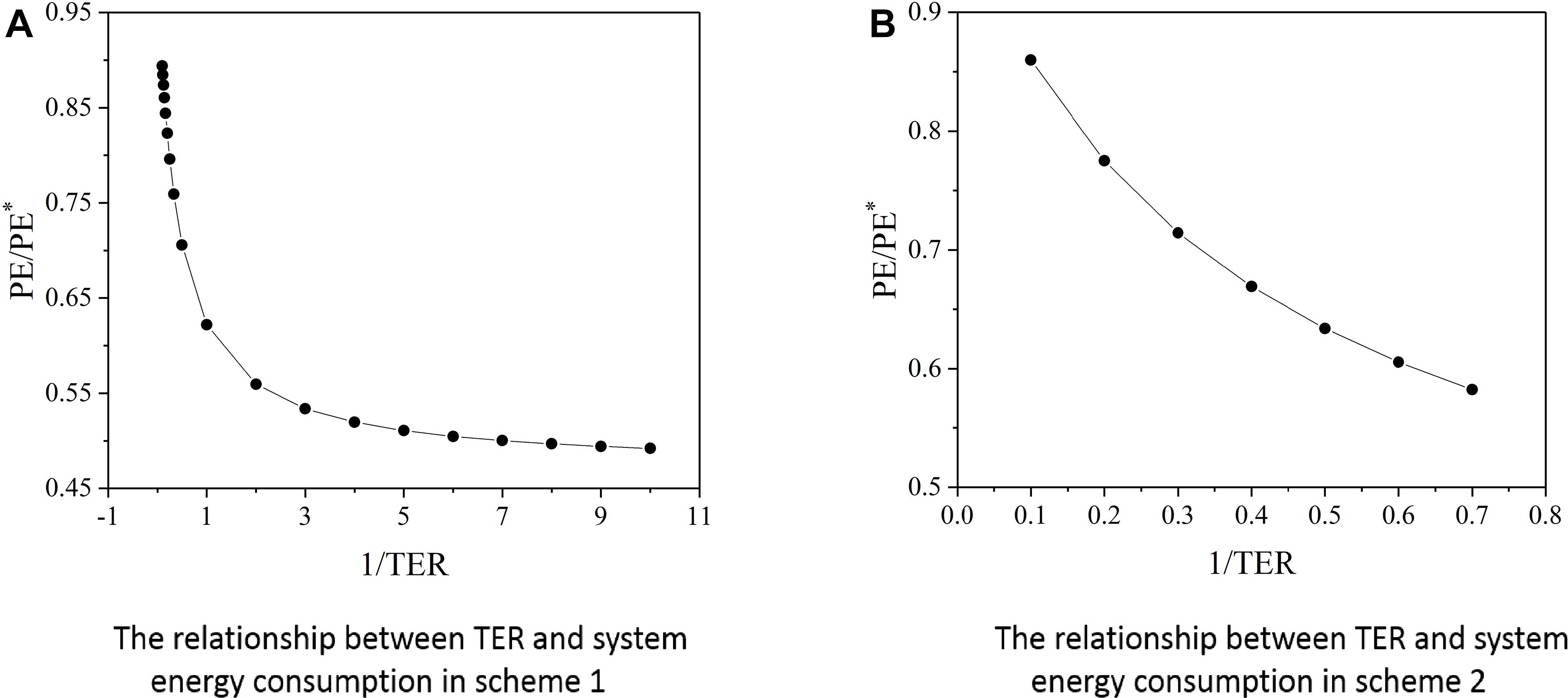
Figure 12. Influence of user’s TER on system energy saving. (A) The relationship between the TER and the system energy consumption in scheme 1. (B) The relationship between the TER and the system energy consumption in scheme 2.
It can be seen from the figure that when the heat and power output of the CHP system is fixed, the primary energy energy saving rate gradually decreases with the increase of the user’s heat and power ratio TER; if the user’s TER is closer to the system’s TER, then the more significant the energy saving effect of the system. Under ideal conditions, when the heat and power output of the CHP system just exactly meets the heat and electricitiy load demand of the user side, that is, the system’s heat to electricity ratio is equal to the user’s TER, the system’s energy saving effect reaches the best.
Since the heat load demand on the user side is basically stable, the energy saving effect of the system can be improved by adjusting the heat and electicity output of the system. For the BG-SOFC-CHP system established in present study, different heat and power output characteristics of the system can be obtained by adjusting parameters such as biomass feed, gasification pressure, gasification temperature, and excess air coefficient, as shown in Figure 13.
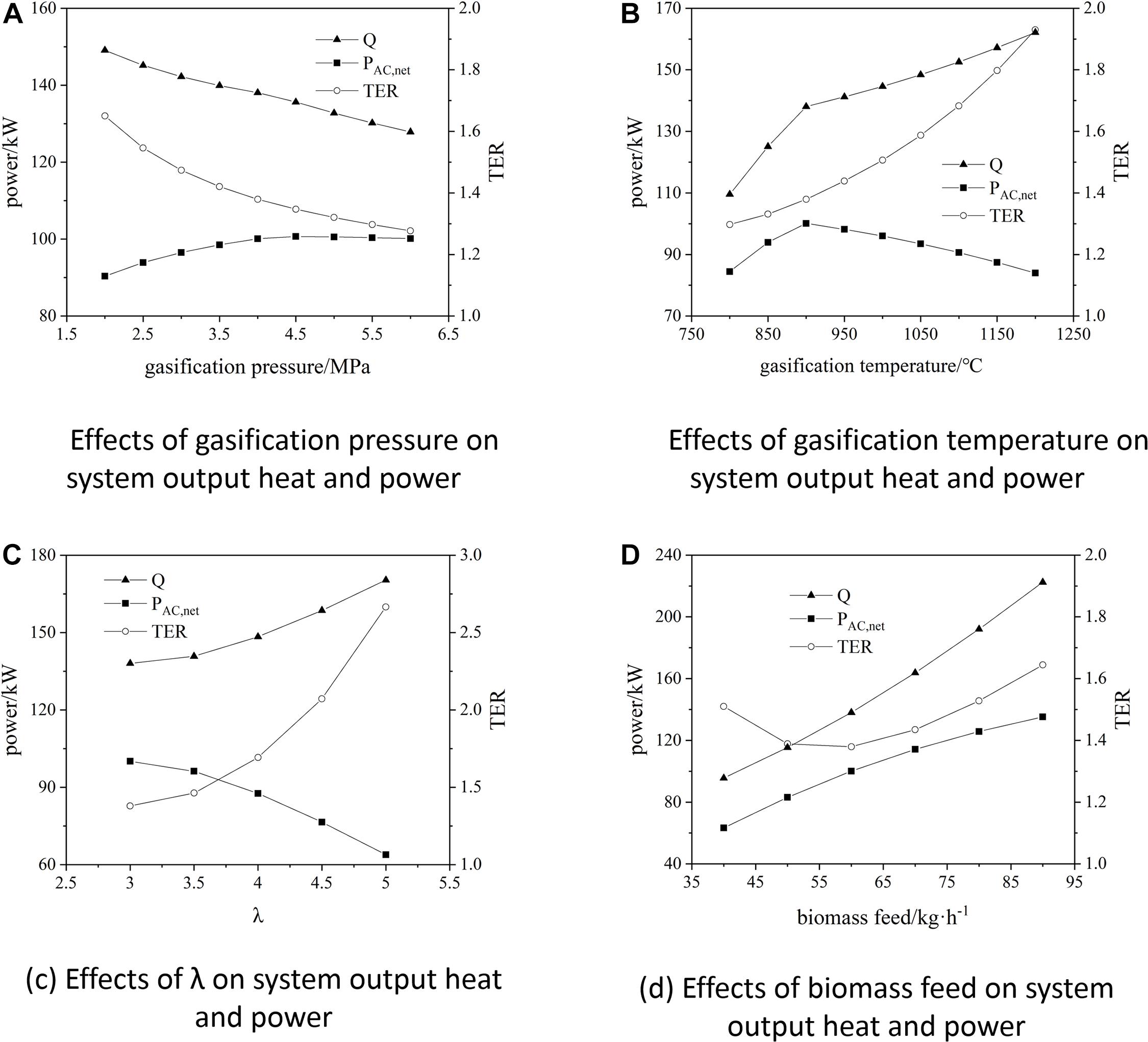
Figure 13. Effect of input parameters on system output heat and power characteristics. (A) Effect of gasification pressure on system output heat and power. (B) Effect of gasification temperature on system output heat and power. (C) Effect of λ on the system output heat and power. (D) Effect of biomass feed on system output heat and power.
It can be seen that as the gasification pressure decreases, the gasification temperature increases, the excess air coefficient increases, and the biomass feed increases, the TER of the system gradually increases; Among them, the influence of gasification temperature and excess air coefficient on the system’s the TER is more significant, which can be used as the main means to adjust the system’s TER. However, it should be noted that the parameters that affect the energy saving effect of the system also include the power generation efficiency and thermal efficiency of the system. The adjustment of the above system parameters will also affect the power generation efficiency and thermal efficiency of the system. At the same time, in order to ensure that the system can operate at a higher efficiency, the adjustment of various parameters should be controlled within a reasonable range.
Conclusion
Based on the BG-SOFC-CHP system with a net power generation capacity of 100 kW, the energy efficiency and economy of the CHP system compared to the traditional system under three different operating schemes have been studied. Through analysis, the following conclusions can be drawn:
1) In the case of heating all rooms in rural houses of northern China, the CHP system has certain energy-saving and economical characteristics but the energy-saving effect is not significant. This is mainly because the TER on the user side is much larger than the TER in the system. Therefore, the advantages of the cogeneration energy supply system cannot be fully utilized;
2) When considering the actual heating situation of rural residences in winter, the energy saving effect of the CHP system is more significant when the operation scheme that meets the average heat load demand of users is adopted, and it also has better economy;
3) When the operation scheme that meets the average electricity load demand of users is adopted, due to the small electricity consumption in rural areas and the strong time period fratures, the role of the CHP system cannot be played well at most times, resulting in the performance of energy saving is reduced, and it is not economical compared to the traditional system;
4) The primary energy savings rates of the three schemes are 8.6, 18.0, and 8.5%; the annual cost savings rates are 5.5, 10.3, and −20.2%; combined with the current situation that the heat load demand in rural areas of northern of China is much greater than the electrical load demand, The second operation scheme is more reasonable and efficient;
5) The main factors affecting the energy efficiency of the CHP system are the system’s heat to electricity ratio TER and the user’s heat to electricity ratio TER. When the system’s TER is constant, as the user’s TER increases, the system’s energy efficiency gradually decreases; when the system’s TER is close to the user-side TER, the energy-saving effect of the system is more significant.
Data Availability Statement
The raw data supporting the conclusions of this article will be made available by the authors, without undue reservation.
Author Contributions
ZD: responsible for the overall organization, conception, and writing of the manuscript. ZJ: responsible for model construction, data analysis, and manuscript writing. JM: responsible for data processing and assist in writing of the manuscript. XS: responsible for data processing and assist in writing of the manuscript. GX: responsible for manuscript conception and method guidance. All authors contributed to the article and approved the submitted version.
Funding
The study was supported by the National Key R&D Program of China 2018YFB1502200.
Conflict of Interest
The authors declare that the research was conducted in the absence of any commercial or financial relationships that could be construed as a potential conflict of interest.
Abbreviations
PE∗, total energy consumption of traditional system/kW ⋅ h; PE, total energy consumption of the CHP system/kW ⋅ h; σD, TER of user side; σCHP, TER of CHP system; ηth,B, boiler thermal efficiency; ηel,CHP, generation efficiency of CHP system; ηth,CHP, thermal efficiency of CHP system; ηel,PP, power plant efficiency; ΔPel, user purchases electricity from the grid/kW; ξel, electricity traditional coefficient; ξth, heat traditional coefficient; CSep, the annual cost of using the traditional system/yuan; CCHP, the annual cost of using the CHP system/yuan; Cel, local grid purchase price/yuan ⋅ kW–1 ⋅ h–1; Ch, heat price when using waste heat boiler/yuan ⋅ kW–1 ⋅ h–1; Cinv, initial investment cost of the traditional system/yuan; Eel, user’s electricity consumption/kW ⋅ h; Eh, user’s heat consumption/kW ⋅ h; R, capital recovery factor; i, annual interest rate; L, equipment life cycle; CBio, price of biomass fuel/yuan ⋅ kg–1; CB, cost of biomass required by the system/yuan; Cinvest, initial investment cost of the CHP system/yuan; CO&M, system operation and maintenance costs (take 4% of initial installation costs); HBio, heating value of biomass fuel/kJ ⋅ kg–1.
References
Achenbach, E. (1994). Three-dimensional and time-dependent simulation of a planar solid oxide fuel cell stack. J. Power Sourc. 49, 333–348. doi: 10.1016/0378-7753(93)01833-4
Amiri, A., Tang, S., Steinberger-Wilckens, R., and Tade, M. O. (2018). Evaluation of fuel diversity in solid oxide fuel cell system. Int. J. Hydrogen Energy 43, 23475–23487. doi: 10.1016/j.ijhydene.2018.10.192
Braun, R. J. (2002). Optimal Design and Operation of Solid Oxide Fuel Cell Systems for Small-scale Stationary Applications. Doctoral dissertation. Madison, WI: University of Wisconsin-Madison.
Chen, G., Xia, Z., Yan, B., Zhou, W., and Wang, Q. (2014). Technical and economic analysis of biomass gasification for heating in rural areas. Renew. Energy Resour. 32, 1395–1399.
Chen, Z., and Zhu, M. (2018). Prediction of residential heating gas demand of Hebei Province after “coal to gas”–based on micro-level survey data of rural household energy consumption. China Prices 7, 64–66.
Cong, H., Zhao, L., Meng, H., Yao, Z., Huo, L., Jia, J., et al. (2018). Applicability evaluation of biomass pyrolytic poly-generation technology on clean heating in northern rural of China. Trans. Chin. Soc. Agric. Eng. 34, 8–14. doi: 10.11975/j.issn.1002-6819.2018.01.002
Dey, T., Singdeo, D., Pophale, A., Bose, M., and Ghosh, P. C. (2014). SOFC power generation system by bio-gasification. Energy Proc. 54, 748–755. doi: 10.1016/j.egypro.2014.07.316
Ehyaei, M. A., and Rosen, M. A. (2019). Optimization of a triple cycle based on a solid oxide fuel cell and gas and steam cycles with a multiobjective genetic algorithm and energy, exergy and economic analyses. Energy Convers. Manag. 180, 689–708. doi: 10.1016/j.enconman.2018.11.023
Giarola, S., Forte, O., Lanzini, A., Gandiglio, M., Santarelli, M., and Hawkes, A. (2018). Techno-economic assessment of biogas-fed solid oxide fuel cell combined heat and power system at industrial scale. Appl. Energy 211, 689–704. doi: 10.1016/j.apenergy.2017.11.029
Jia, J., Abudula, A., Wei, L., Sun, B., and Shi, Y. (2015). Thermodynamic modeling of an integrated biomass gasification and solid oxide fuel cell system. Renew. Energy 81, 400–410. doi: 10.1016/j.renene.2015.03.030
Li, G., Liu, C., Li, X., and Chi, L. (2015). Test of heating effect of heating system based on biomass briquette stove in rural area. Gas Heat 35, 13–16. doi: 10.13608/j.cnki.1000-4416.2015.12.004
Li, Y., Ruan, Y., and Liu, Q. (2015). Performance analysis of micro combined heat and power system based on building load. CIESC J. 66, 364–370. doi: 10.11949/j.issn.0438-1157.20150709
Palomba, V., Prestipino, M., and Galvagno, A. (2017). Tri-generation for industrial applications: Development of a simulation model for a gasification-SOFC based system. Int. J. Hydrogen Energy 42, 27866–27883. doi: 10.1016/j.ijhydene.2017.06.206
Pohl, E., and Diarra, D. (2014a). A method to determine primary energy savings of CHP plants considering plant-side and demand-side characteristics. Appl. Energy 113, 287–293. doi: 10.1016/j.apenergy.2013.07.038
Pohl, E., and Diarra, D. (2014b). Assessment of primary energy savings by means of CHP systems in domestic energy supply. Appl. Ther. Eng. 71, 830–837. doi: 10.1016/j.applthermaleng.2013.12.021
Rokni, M. (2018). Design and analysis of a waste gasification energy system with solid oxide fuel cells and absorption chillers. Int. J. Hydrogen Energy 43, 5922–5938. doi: 10.1016/j.ijhydene.2017.10.123
Sadat, S. M. S., Lavasani, A. M., and Ghaebi, H. (2019). Economic and thermodynamic evaluation of a new SOFC based polygeneration system. Energy 175, 515–533. doi: 10.1016/j.energy.2019.03.093
Tsinghua University (2020). Designer’s Simulation Toolkit. Available online at: https://update.dest.com.cn/
Wan, W. (2016). An innovative system by integrating the gasification unit with the supercritical water unit to produce clean syngas for solid oxide fuel cell (SOFC): system performance assessment. Int. J. Hydrogen Energy 41, 22698–22710. doi: 10.1016/j.ijhydene.2016.09.146
Yan, Y., Jiao, W., Wang, K., Huang, Y., Cheng, J., and Han, Q. (2020). Coal-to-gas heating compensation standard and willingness to make clean energy choices in typical rural areas of northern China. Energy Policy 145:111698. doi: 10.1016/j.enpol.2020.111698
Zhang, D., Li, J., and Zhang, H. (2017). All operation mathematical model and thermal performance analysis on combined heating power and biogas system. CIESC J. 68, 1998–2008. doi: 10.11949/j.issn.0438-1157.20161538
Zhou, R., Zhang, X., and Yan, R. (2019). Application of biomass energy-solar energy combined heating system in northern rural areas. China Biogas 37, 108–113.
Keywords: biomass gasification, solid oxide fuel cell, combined heat and power system, operation scheme, performance analysis
Citation: Dang Z, Jiang Z, Ma J, Shen X and Xi G (2021) Numerical Study on the Performance of a Cogeneration System of Solid Oxide Fuel Cell Based on Biomass Gasification. Front. Energy Res. 9:609534. doi: 10.3389/fenrg.2021.609534
Received: 28 September 2020; Accepted: 30 March 2021;
Published: 21 April 2021.
Edited by:
Dong Ding, Idaho National Laboratory (DOE), United StatesReviewed by:
Aleksey Yaremchenko, University of Aveiro, PortugalLei Bi, University of South China, China
Copyright © 2021 Dang, Jiang, Ma, Shen and Xi. This is an open-access article distributed under the terms of the Creative Commons Attribution License (CC BY). The use, distribution or reproduction in other forums is permitted, provided the original author(s) and the copyright owner(s) are credited and that the original publication in this journal is cited, in accordance with accepted academic practice. No use, distribution or reproduction is permitted which does not comply with these terms.
*Correspondence: Zheng Dang, emRhbmdAbWFpbC54anR1LmVkdS5jbg==