 Yan Liu
 Shu Liu2*
 Fuyi Cao
- 1Graduate Department, Shenyang Institute of Engineering, Shenyang, China
- 2School of Renewable Energy, Shenyang Institute of Engineering, Shenyang, China
- 3Science and Technology Division, Shenyang Institute of Engineering, Shenyang, China
Yaw system is an important part of wind turbine control system, yaw error is an important performance index of wind turbine, which has great influence on power generation. The wind utilization and the output of the power generation have been determined by the yaw error. In order to make the wind turbine better aligned toward the wind direction, reduce the yaw error, and increase the power generated by the unit, the angle errors of yaw control of wind turbine have been analyzed, in this paper, and the method of wind test, the strategy of yaw control have been studied respectively. Based on the results of the study, the method of wind test, the restart control strategy of yaw system and the performance of control strategy of yaw system have been optimized in this paper. In this way, the three important links are optimized, it will effectively reduce the yaw error as well as significantly improve the wind turbine generating electricity.
Introduction
Energy crisis and environmental pollution are two of the most important issues which human faces, and are highly concerned by relevant research institutions and governments around the world. The development of renewable energy can effectively alleviate energy shortages and environmental pollution in the world, such as global warming and smog. As its huge reserves, renewable, widely distributed, pollution-free as well as the most nature development technology and the largest development conditions, economic benefits, and many other advantages, wind power meet the requirements of the sustainable development of human and the form of renewable energy in wind power is the most development potential forms of energy. The development and utilization of wind energy has been highly valued by countries around the world and has become the fastest growing source of clean energy (Albadi and El-Saadany, 2010; Sun et al., 2011; Shen and Du, 2015; Wang et al., 2016).
In order to make wind energy more efficient, large wind turbines often need to be active and accurate. If the yaw control makes a angel error on the efficiency of the wind turbine, the greater it makes, the more power will be lost. At the same time, wind turbines can cause unnecessary damage to the unit if it is not accurate. Therefore, it is very important to calibrate and optimize the yaw control.
Yaw Control Overview
Overview of the Yaw System Restart Strategy
Authority of the literature retrieval results show that large wind turbines yaw system restart strategy is simple, mainly uses the simple yaw angle error and time delay threshold setting to be judgment, when the wind angle error is greater and longer than the setting threshold, the start back to the wind, in pursuit of the wind speed and theory of maximum power generation as the goal. Most of the wind turbines are rebooted in the wind strategy. Only a small number of wind turbines will be determined by differentiating each other with high speed and low wind speed respectively.
Overview of Yaw Control Strategy
More and more experts and scholars pay attention to the research on the wind control strategy of yaw control system in the wind turbine. Many research have made advances. At present, the representative research results are as follows:
These proposed a hill climbing control algorithm for yaw system (Jacobson and Yucesan, 2004; Zou et al., 2010): this algorithm comes from a hill climbing control (HCC) with power detection. The algorithm can determine the optimal yaw angle of wind turbine by finding the maximum power generation, and has good yaw control accuracy. At the same time, it has the advantages of easy software implementation, good real-time performance and no need of wind direction sensor. The algorithm improves the accuracy of wind control, but its control parameter threshold is mostly set according to experience, so it can't be quantified, and the problem of under yaw and over yaw is not solved completely. This method has limited practical application significance for engineering. If the control parameters are not set properly, it is easy to cause frequent rotation of the yaw system, resulting in additional mechanical wear of the yaw system, and the reliability of the unit is reduced (Mei, 2020).
The control strategy of yaw system based on VHC algorithm is studied in reference (Piao and Wang, 2008; Cheng, 2017). This algorithm aims to search the maximum output power of the wind turbine in the yaw process, and can improve the wind accuracy of the engine room. At the same time, the VC control algorithm based on wind vane can also be applied to a wide range of wind direction changes, which meets the robustness of wind direction changes. The disadvantage is that the judgment of wind direction will be invalid within ±15° and other methods should be used for yaw control.
These proposed a yaw system control strategy based on KHC algorithm: the algorithm is also an algorithm of power detection (Gu et al., 2011; Gao et al., 2019), which can carry out accurate wind response to a certain extent in the range of small wind direction change. However, when the wind direction changes in a very small range and the interference situation will cause frequent action of the yaw system, which will reduce the comprehensive benefits of the yaw system.
They study the control strategy of PIDNN yaw system: this control strategy is based on CPSO algorithm and is improved by random cooperative particle swarm optimization (CRPSO) (Piao et al., 2009; Piao and Wang, 2010; Liu, 2018). It combines the advantages of CRPSO algorithm and PSO algorithm. It not only keeps the diversity of particles, but also improves the convergence speed of the algorithm. The robustness of yaw system is also enhanced. However, due to the influence of hardware and load design of wind turbines in operation, the intelligent simulation algorithm is difficult to apply.
It studies the control strategy of the yaw system based on fuzzy control algorithm (Gao and Wang, 2020): the reference proposes that the fuzzy control of the yaw system can fuzzify the input information and formulate the fuzzy control rules (Piao et al., 2009). However, compared with the scheme of combining fuzzy control with traditional PID controller in reference (Gao and Wang, 2020), the function and advantages of this fuzzy control are slightly single. This combined control in reference forms a new control method, namely FUZZY-PID piecewise compound control (Li et al., 2007). The fuzzy control in the initial stage has good dynamic performance and can reduce overshoot; the PID control in the later stage can reduce the steady-state error of the system.
Reference proposed that the control algorithm based on artificial neuroendocrine immune regulation is a common deviation processing algorithm (Chen and Yang, 2009). This paper analyzes and studies immune regulation control, and puts forward the "wind deviation unit" and "wind error processing unit" which can simulate the immune system of the body; the "control unit" is used to simulate the secretion system; the "optimization unit" is used to simulate the neural system, and the adaptive neural system with maximum power tracking is established to realize accurate and effective control of the yaw system. However, in the active yaw process of the megawatt wind turbine yaw system, the vibration amplitude and noise will inevitably increase greatly, which will lead to poor uniformity of active yaw motion of MW class wind turbine yaw system, and it is easy to produce impact, which will ultimately affect the accuracy of megawatt wind turbine yaw control system.
In order to ensure the stability and improve the rapidity of the yaw system, so as to realize the maximum capture of wind energy by wind turbine, this paper optimizes the three important links in the yaw process of the wind scheme, the yaw restart strategy and the yaw execution strategy respectively, so as to realize the reasonable division of the yaw control range of the wind turbine and the reasonable optimization of the yaw error, so as to make the yaw parameters reasonable It has higher adaptive level and pertinence, so as to improve the generating capacity of the unit.
Manuscript Formatting
The Interference of Wind Wheel Rotation on Wind
In the actual development of wind power, the wind measuring equipment used in most wind farms is anemometer, which is generally installed on the engine room of wind turbine. Although this installation method is a reasonable and preferred scheme for a long time, from the analysis of space location, this installation location scheme is not a perfect choice. During the standby or operation of the unit, the wind turbine located in front of the engine room often interferes with the airflow directly in front of the engine room, which changes the airflow vector originally arriving at the wind measuring equipment, resulting in the wind speed and direction data measured by the anemometer no longer belong to the airflow data in front of the wind turbine. The biggest impact is that the measured wind direction data and the data in front of the wind wheel have a large error. If the yaw response is carried out, the wind turbine can not actually face the wind direction, and there will be an error angle, which will affect the generation efficiency of the wind turbine (Zhu et al., 2011; Meisamiazad et al., 2012). The simulation diagram of the interference of wind wheel rotation on airflow is shown in Figure 1.
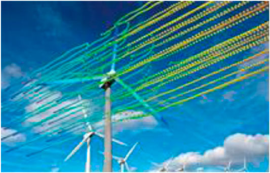
FIGURE 1. The wind wheel turns the interference simulation of the air flow.
Using Machine-Class Radar Wind Measurement
In order to reduce the interference of the wind turbine on the wind measuring equipment in the cabin, we use a more mature remote sensing wind technology, as well as a new wind measurement technology—laser radar wind, at present. The cabin type laser radar wind measuring instrument is installed above the nacelle of the wind turbine, and can accurately measure the wind direction data of the horizontal direction in front of the wind turbine.
The data measured by the nacelle radar is the angle between the wind speed of the front of the wind turbine and the wind direction of the wind wheel and the direction of the incoming and outgoing wind. It can obtain the yaw angle directly. Therefore, the installation accuracy of lidar wind meter strictly affects the test results. In the process of testing, we should adopt reliable installation methods and optimize the wind measurement data by calibrating the installation accuracy (Zhang et al., 2010).
As shown in Figure 2, firstly, the standard line parallel to the axial direction of the engine room shall be delimited by GPS positioning or clamping tooling. The standard line shall be as close as possible to the wind meter and extend to the rear of the installation position of the wind meter. A laser beam is shot from the head position and tail position of the anemometer to determine point a and point B. by measuring the distance between point a and point B to the standard line, the nose direction is adjusted. When the distance between point a and point B to the standard line is equal, fix the position of the head to ensure that the horizontal direction of the wind meter head is parallel to the standard line, and that the horizontal direction of the wind meter head is parallel to the axial direction of the engine room.
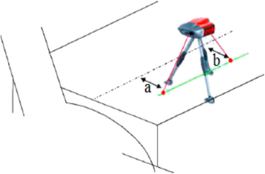
FIGURE 2. Calibration of laser radar measuring instrument installation location.
Optimization of Wind Measurement Error
Analysis of Wind Measurement Conditions
The calculation formula of power output of wind turbines is:
In the formula ρAir density; R—The rotor radius; Cp—Wind power utilization coefficient; V—The wind speed.
The increase of Mechanical power output of wind turbines is expressed as (Let's say that
In the formula ΔPThe increase of power output when the wind speed increases
As the formula shown, power output of wind turbines shows different growth rates in different wind speed zones. It exists the trend that the growing rate of the medium-speed zone is fast, the low speed zone is slow, and the high speed zone remains the same.
Figure 3 shows that the power characteristics of units in different wind speed ranges are affected by wind changes differently. In high and low wind speed sections, wind changes have little influence, while wind in medium speed sections are greatly affected.
In the formula ΔP′The increase of power output when wind speed increases
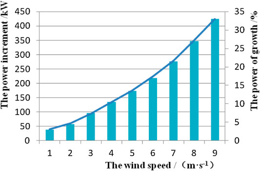
FIGURE 3. Diagram of growth of output power correspond to 1 m/s increase in wind speed.
By Formula (3), the same error angle changes in different wind speed range on the power characteristics is also different. Based on the above characteristics of wind turbines, in the yaw control error data analysis, we should distinguish between different wind speed sections and calculate yaw control error.
Yaw Control Error Test
In order to reduce the uncertainty of the analysis results, starting from 1 times before impeller diameter every 0.5 times the impeller diameter distance setting test point, at least four times before measuring impeller should be within the scope of wind speed and relative wind data, each test point from cut into the wind speed to each rated wind speed 0.5 m/s should be measured at least three sets of data. The average of the yaw control deviation is calculated for each measurement distance according to formula (4) (Zhao et al., 2015).
In the formula: DYi—Yaw control deviation of measuring distance number for i; DY—The average of 10 min DYi of different measurements.
In the formula: DRMS—the standard deviation of the measured distance measurement.
In order to more accurately calculate the yaw control deviation of the unit, the data is analyzed before the data analysis. The principle of screening is as follows:
The unit is in normal operation;
The measuring data of the laser wind instrument should be greater than 0.3. The deviation of yaw control was calculated by using formulas (6) and (7).
In the formula:
In the formula:
Optimization Results
The measurement range of the radar is 10–300 m (vertical and horizontal). The accuracy of the measurement accuracy is high, the accuracy of the wind speed is 0.1 m/s, the accuracy of the wind direction is 0.5°; The instrument has a wide operating temperature range and is capable of meeting the temperature range of −30 to +45°C (Tan and Islam, 2004). The main parameters of the wind turbine for testing are shown in Table 1.
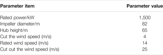
TABLE 1. The main parameters of the wind turbine tested.
Test the data every 10 min. The test distance of lidar wind meter is set as 5 m, 45 m, 82 m, 123 m, 164 m, 185 m, 205 m, 225 m and 246 m. The yaw error measured by lidar wind meter at each distance is shown in Table 2.
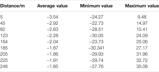
TABLE 2. Yaw error data at each distance of the radar.
In this paper, we use MATLAB for analysis, and draw the test data of the general changes, as shown in Figure 4, the minimum, maximum and average changes shown in Figure 5.
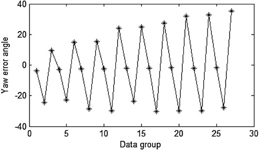
FIGURE 4. Variation curve of yaw error angle.
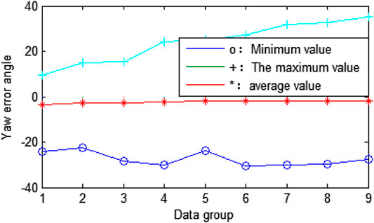
FIGURE 5. The variation of the minimum, maximum and mean of the yaw error.
From the above test, we can see that the yaw data at the distance of the radar are basically in the range of [−30, +30°], and the distribution is roughly the same. Therefore, the following analysis of the yaw error data at the distance of 5 m from the front of the radar and at the location of the cabin itself (0 m) is carried out.
The parabolic error statistics at the distance of 5 m from the front of the radar and the 0 m distance are shown in Table 3.
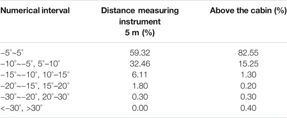
TABLE 3. Measurement of yaw error at 5 m distance and 0 m from radar.
According to the results of the yaw error test in Table 3, this paper still uses MATLAB for analysis, and draws the approximate distribution of the test data of 5 m distance and the cabin's own position (0 m distance), as shown in Figure 6.
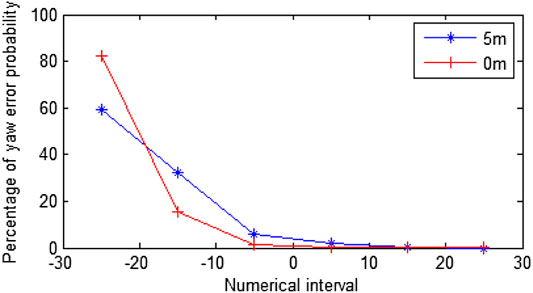
FIGURE 6. Percentage of yaw error at 5 m distance and 0 m distance from the wind measuring instrument.
From the above analysis we can see that the probability of yaw error at 5 m of the radar is much smaller than the probability of occurrence of yaw error at 0 m. So it is not difficult to draw the conclusion: to improve the wind program, the proposed cabin-type radar wind test program can effectively optimize the yaw error.
Through the cabin-type radar wind test program can effectively reduce the yaw error, and improve power generation. According to the field test the power generation data, the use of the wind program can make the wind power generation capacity increased by about 2.04%.
Optimization of Yawing Control Strategy
Optimization of Yaw System Restart Strategy
The Working Principle of Yaw System Restart Strategy
The yaw control system is an important part of the horizontal axis wind turbine control system. According to the wind direction signal detected by the wind vane at the rear of the engine room, the yaw control system can actively control the wind (Bianchi et al., 2005; Luo et al., 2014). The working principle diagram is shown in Figure 7.
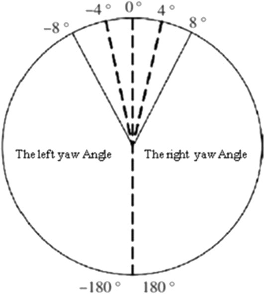
FIGURE 7. Schematic diagram of automatic yaw control strategy.
The 0° of the dashed line indicates the 0° position of the wind vane, and the probability distribution of the wind error of the 1# and 2# units is also counted. The statistical results are shown in Figure 8. It can be seen that the wind error distribution of the unit is roughly normal distribution. The probability of wind error near 0° is the largest. When the cabin of the wind error occurs in the [−8°, 8°] (this range is set to allow the error range), this time the default is the wind state, the cabin is not yaw. When the wind error detected by the wind vane exceeds the allowable range, the system will issue a yaw command. When the wind direction is in the left side of the cabin, the system will issue a left yaw command; when the wind direction is in the right side of the cabin, the system will issue a right yaw command. The delay time Td can be set according to the wind speed, and the wind vane checks the current wind error after the end of the delay. When it returns to the setting range [−4°, 4°], the yaw is terminated (Zhang et al., 2013).
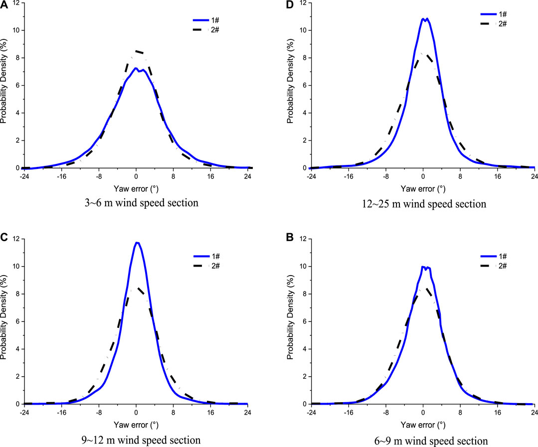
FIGURE 8. Probability distribution of wind error in different wind speed stations.
The Relationship Between Wind Error and Wind Speed
According to the wind speed data of the scene, the wind speed probability distribution curves of 1# and 2# units are plotted, as shown in Figure 9. When the wind speed is segmented, the mean and standard deviation of the wind error of each wind speed interval can be calculated, and the curves of the mean and standard deviation of wind error are obtained respectively, as shown in Figure 10 and Figure 11.
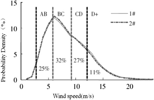
FIGURE 9. Wind speed probability distribution curve.
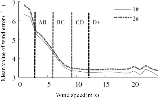
FIGURE 10. The curve of the average wind error vs. wind speed.
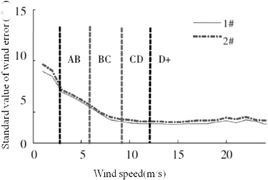
FIGURE 11. The curve of wind error standard value changes with wind speed.
Optimization of Yaw Error
In view of the shortage of wind control strategy for yaw restart, which has few different wind speed segments for differential control, we can improve the control strategy by introducing different wind speed segments.
The area above the cut in wind speed is divided into four sections for analysis.
1. AB segment (wind speed of 3–6 m/s):
The distribution probability of wind speed in this section is 25%, and the mean value and standard deviation of wind error are large, resulting in poor control performance of yaw system;
2. BC segment (wind speed 6–9 m/s):
In the middle section of rated wind speed, the distribution probability of this section accounts for 32%. Compared with AB segment, the average value and standard deviation of wind error are smaller, and the control performance of yaw system is improved;
3. CD segment (wind speed is 9–12 m/s):
In the high wind speed section under rated wind speed, the distribution probability accounts for 27%. The average value and standard deviation of wind error do not change with wind speed, which indicates that the following ability of yaw control can meet the demand of wind direction change;
4. D + (wind speed greater than 12 m/s):
Above the rated wind speed, the wind direction is relatively stable and the performance is at the highest level.
After segmenting, the probability distribution curve of wind error of the unit at different wind speeds is shown in Figure 8.
Optimization of Yaw Strategy
At present, in actual wind power development applications, wind turbines set the yaw control with the "yaw tolerance angle" setting. In order to avoid frequent motion of the unit yaw, when the wind error is greater than the set yaw tolerance angle, wind turbines will yaw to wind. The accuracy of the control method is low, and it will affect the unit's wind energy efficiency. In view of this situation, this paper starts from the actual operation of the wind turbine and analyzes the control performance of the yaw system of the wind turbine by the historical operation data of the unit, and puts forward the optimization scheme of the yaw control strategy.
Because the yaw system of the wind turbine belongs to the nonlinear time-varying system, there will be a large disturbance of the parameter change and the disturbance of the load. Therefore, it is very difficult to establish the precise mathematical model. In this paper, the fuzzy yoke controller is used to adjust the parameters on-line to meet the different requirements of the yaw control parameters. The structure of the variable-domain Fuzzy-PID yaw controller is shown in Figure 12.
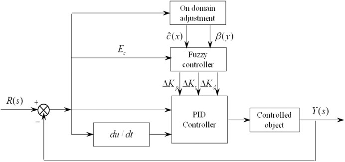
FIGURE 12. The domain fuzzy PID bias controller block diagram.
Fuzzy PID control Compared with variable Universe fuzzy control, fuzzy PID control can respond quickly to the changing wind direction, and can maintain the power output of wind turbine unit stably. Table 4 shows the comparative simulation of the yaw system simulation table. Based on the analysis of the simulation statistics, the fluctuation of the wind speed is obviously reduced, the standard deviation of the wind speed is reduced by 32.8%, the standard deviation of the wind wheel torque is reduced by 16.9%, and the wind power is obviously improved Stability of the unit.
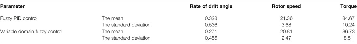
TABLE 4. Simulation statistics analysis.
Although the variable domain fuzzy control yaw can keep the error within 2°, the number of yaw operations is shortened by about 3% during the whole experimental period, which can effectively prolong the service life of the wind turbine. The analysis above shows that the way based on the variable domain fuzzy control can effectively reduce fatigue of yaw actuator, as well as the abrasion between components and the vibration of engine room, which can effectively reduce the failure rate level of wind turbine. When the control way is used for yaw control, the manipulation data of yaw error are seen in Table 5. When draught fan is affected by wind direction, the yaw angle of fuzzy control can be kept within 20°, which illustrates that the control is feasible.
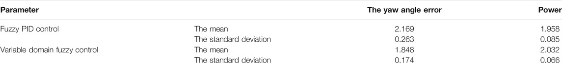
TABLE 5. Yaw system experiment compared statistics.
According to the experimental comparison data given in Table 5, the stability of fuzzy-PID yaw control system is better than pure fuzzy-PID control. The use of variable-universe fuzzy-PID yaw can maintain errors within 2°, and the number of yaw execution actions will be reduced by about 3% throughout the experimental period, which can extend the service life of wind turbines.
Conclusion
In this paper, the yaw error analysis and optimization are carried out for the three important links of the yaw control system, namely wind measurement, yaw restart and yaw execution. After the improvement of the scheme, combined with authoritative literature, the three links can improve the power generation to a certain extent. The following is a summary of the assessment of generation growth after optimization:
• Optimization stage of wind measurement:
Based on the analysis of the wind measurement scheme, it is proposed that the engine room lidar wind measurement instead of the mechanical crosswind instrument can improve the accuracy of wind measurement, effectively reduce the yaw error, and increase the power generation by about 2.04%.
• Optimization of yaw system restart:
Based on the research of restart wind strategy, the yaw error angle and delay threshold can be adjusted by different wind speed segments, which can effectively reduce the yaw error and improve the power generation.
• Optimization of strategy of yaw control:
For the study of the implementation of the wind strategy, the use of variable Universe fuzzy control, the yaw error is effectively optimized, power generation is improved.
In this paper, through the study on the various parts of the yaw control system, the yaw strategy has been improved and optimized, the common yaw error problems of the current wind turbine have been optimized, which has certain practical significance and effect to improve the power generation. Ideally, the yaw error optimization in this paper can significantly increase the power generation.
This method has operability and effect, and it is suitable for the optimization and improvement of generating performance of units in the operating wind farm.
Data Availability Statement
The original contributions presented in the study are included in the article/Supplementary Material, further inquiries can be directed to the corresponding author.
Author Contributions
All authors listed have made a substantial, direct, and intellectual contribution to the work and approved it for publication.
Funding
Fund project: Major Scientific Research Projects of Inter-university Cooperation of General Undergraduate Universities in Liaoning Province; Project name: Research on Non-destructive Detection Method Based on Wind Turbine Blade Surface Condition; Project category: Industrial research and industrialization guidance plan; Project number: JL-2014; Project time: October 1, 2019 - September 30, 2021; Project amount: 30000yuan.
Conflict of Interest
The authors declare that the research was conducted in the absence of any commercial or financial relationships that could be construed as a potential conflict of interest.
References
Albadi, M. H., and El-Saadany, E. F. (2010). Overview of wind power intermittency impacts on power systems. Elec. Power Syst. Res. 80 (6), 627–632. doi:10.1016/j.epsr.2009.10.035
Bianchi, F. D., Mantz, R. J., and Christiansen, C. F. (2005). Gain scheduling control of variable-speed wind energy conversion systems using quasi-LPV models. Contr. Eng. Pract. 13 (2), 247–255. doi:10.1016/j.conengprac.2004.03.006
Chen, F., and Yang, J. (2009). “Fuzzy PID controller used in yaw system of Wind Turbine”, in Paper presented at the International Conference on Power Electronics Systems & Applications.
Cheng, L. (2017). Study on Yaw System Error and Control Strategy of the Wind Turbine [Dissertation]. Beijing: North China Electric Power University.
Gao, F., Ling, X., and Liu, Q. (2019). Parameter optimization of yaw control for wind turbine based on SCADA data. Acta Energ. Solaris Sin. 40 (06), 1739–1746. doi:10.1155/2014/516394
Gao, S., and Wang, C. (2020). Calculation method study of wind turbine yawing reduction coefficient based on measured data. Acta Energ. Solaris Sin. 41 (10), 246–250. doi:10.3390/app10010410
Gu, L., Yue, X., Yang, Y., and Li, S. (2011). Application of Kalman Hill Climbing Control Algorithm in yaw control system of wind power generation unit. Huadian Technol. 33 (09), 92–94+98.
Jacobson, S. H., and Yücesan, E. (2004). Analyzing the performance of generalized hill climbing algorithms. J. Heuristics 10 (4), a9. doi:10.1023/B:HEUR.0000034712.48917
Li, Y., Wen, Z., Zhao, S., and Chen, L. (2007). Research on fuzzy logic controlling of wind driven-generator yaw system. Modern Machinery 1, 29–30+37. doi:10.3390/en12152862
Liu, C. (2018). Design of wind turbine yaw control system based on KHC algorithm. [Dissertation]. Changchun: Changchun University of Technology.
Luo, Y., Li, J., Chen, L., Li, Q., and Jia, Y. (2014). Method study of on-line risk analysis for district grid. Adv. Technol. Electr. Eng. Energy 33 (12), 60–64+70.
Mei, Y. (2020). Optimization of maximum power point tracking strategy for doubly-fed wind power system with large inertia [Dissertation]. Shanghai: Donghua University.
Meisamiazad, M., Grigoriadis, K. M., and Song, G. (2012). Anti-windup linear parameter varying control of structural systems with magneto-rheological dampers. J. Vib. Contr. 19 (12), 1779–1794. doi:10.1177/1077546312451300
Piao, H., and Wang, Z. (2010). Control strategy of CPSO-based PID neural network and a yaw motor. Electr. Mach. Contr. 14 (09), 55–62. doi:10.15938/j.emc.2010.09.011
Piao, H., and Wang, Z. (2008). Research on a new algorithm of wind turbine yaw control system--V-HC. Acta Energiae Solaris Sin. 8, 1028–1033. doi:10.1155/2014/516394
Piao, H., Wang, Z., and Zhang, H. (2009). Cooperative-PSO-based PID neural network integral control strategy and simulation research with asynchronous motor controller design.
Shen, X., and Du, W. (2015). Expectation and review of control strategy of large wind turbines yaw system. Trans. China Electrotech. Soc. 30 (10), 196–203. doi:10.19595/j.cnki.1000-6753.tces.2015.10.027
Sun, L., Gong, Y., Wang, Z., Zhang, Z., Meng, Y., and Qi, L. (2011). “Design of Large-scale wind power yawing bearing test-bed control system”, in Paper presented at the Proceedings of 2011 International Conference on Fluid Power and Mechatronics.
Tan, K., and Islam, S. (2004). Optimum control strategies in energy conversion of PMSG wind turbine system without mechanical sensors. IEEE Trans. Energy Convers. 19 (2), 392–399. doi:10.1109/TEC.2004.827038
Wang, X., Wu, G., Pan, D., and Ying, Y. (2016). Wind turbine yaw control optimization utilizing the running data. Renew. Energy 34 (03), 413–420. doi:10.13941/j.cnki.21-1469/tk.2016.03.015
Zhang, L., Ye, T., Xin, Y., Han, F., and Fan, G. (2010). Problems and measures of power grid accommodating large scale wind power. Proc. Chin. Soc. Electr. Eng. 30 (25), 1–9. doi:10.13334/j.0258-8013.pcsee.2010.25.001
Zhang, Y., Chen, Z., and Cheng, M. (2013). Proportional resonant individual pitch control for mitigation of wind turbines loads. IET Renew. Power Gener. 7 (3), 191–200. doi:10.1049/iet-rpg.2012.0282
Zhao, Y., Lv, Q., Zhu, Q., Wang, J., and Li, W. (2015). Overview on issues related to reserve capacity by wind power connected to the grid. Renew. Energy Resourc. 33 (04), 565–571. doi:10.13941/j.cnki.21-1469/tk.2015.04.012
Zhu, C., Li, P., Wang, J., and Xu, X. (2011). Research on intelligent controller of wind-power yaw based on modulation of artificial neuro-endocrine-immunity system. Proc. Eng. 15, 903–907. doi:10.1016/j.proeng.2011.08.167
Keywords: yaw control error, radar test wind, sub-wind speed control, variable universe fuzzy control, optimal design
Citation: Liu Y, Liu S, Zhang L, Cao F and Wang L (2021) Optimization of the Yaw Control Error of Wind Turbine. Front. Energy Res. 9:626681. doi: 10.3389/fenrg.2021.626681
Received: 06 November 2020; Accepted: 05 January 2021;
Published: 08 February 2021.
Edited by:
Minh Quan Duong, The University of Danang, VietnamReviewed by:
Cong-Trang Nguyen, Ton Duc Thang University, VietnamVladimir Tanasiev, Politehnica University of Bucharest, Romania
Copyright © 2021 Liu, Liu, Zhang, Cao and Wang. This is an open-access article distributed under the terms of the Creative Commons Attribution License (CC BY). The use, distribution or reproduction in other forums is permitted, provided the original author(s) and the copyright owner(s) are credited and that the original publication in this journal is cited, in accordance with accepted academic practice. No use, distribution or reproduction is permitted which does not comply with these terms.
*Correspondence: Shu Liu, MTI0Mjg1NzY4MkBxcS5jb20=