 Guoqing Li
 Song Zhang
 Shuguang Li
 Xianchao Liu
- Department of Electrical Engineering, Northeast Electric Power University, Jilin, China
This paper presents a region boundaries determination method for critical commutation failures (CF) in multi-infeed high-voltage direct-current (HVDC) systems under unbalanced short circuit faults. By using the nodal impedance matrix, a calculation approach for the converter extinction angles is deduced. First, the extinction angles under unbalanced short circuit faults are calculated. If the extinction angle of a bus is less than the minimum extinction angle, the bus is a failed bus set. By this means, region boundaries of critical commutation failures are demarcated by examining each bus in the AC system. Finally, the effectiveness of the proposed approach was verified by using a modified IEEE 39-bus system.
Introduction
Multi-infeed high-voltage direct-current (HVDC) is widely used in power grids for its advantages in long-distance power transmission (Yao et al., 2020; Mirsaeidi et al., 2018). Commutation failure (CF) at the inverter side is a very frequent dynamic event in multi-infeed HVDC systems (Wang Q. et al., 2019; Zheng et al., 2019). An AC system failure may cause commutation failure (CF) at the convertor station near a fault location (Wang F. et al., 2017; Xue et al., 2018). If the commutation function is not recovered quickly, it may lead to a bulk drop of HVDC transmission power and the continuous CFs will occur at the local and adjacent inverter station, which will lead to a wide-range power outage. However, not all AC system faults can trigger the CF of a DC system. In view of the rapid construction and deployment of DC transmission systems, it is important to establish an accurate and fast solution to detect commutation faults and reduce or avoid simultaneous commutation failures in multiple DC transmission systems.
A great amount of research in the field of CF analysis has proposed that a decrease in the extinction angle of the inverter and the drop of commutation voltage are the primary causes of the CF (Yao et al., 2020; Xiao et al., 2016; Xue et al., 2016). In reference (Wang J. et al., 2019), based on the expected value of reactive power consumption of inverter stations, a method for calculating DC command values by real-time measurement of AC bus voltage is proposed. In reference (Guo et al., 2015), a method of setting different current command values for different fault types of AC system is proposed. Similarly, in order to reduce reactive power consumption when the system recovers from CF (Wei et al., 2014), HVDC recovery is promoted by reducing the current command value. Reference (Li et al., 2017) proposes a method of demarcating critical failure impedance boundary of multi-infeed HVDC systems based on the minimum extinction angle, but the types of short circuit failures it considered were not comprehensive enough.
In this paper, the method of demarcating critical failure impedance boundary in reference (Li et al., 2017) is further supplemented. The Extinction Angle of a converter station is calculated when any bus has a two-phase fault and line fault in an AC system. When an unbalanced short circuit fault occurs in an AC system, the critical impedance boundary of a multi-feed DC system can be identified from the network topology by taking the critical extinction Angle as the criterion. An unbalanced short-circuit fault of a node lying within the critical fault impedance boundary is more likely to cause CF in a DC system, whereas an unbalanced fault of a node outside the boundary will not cause CF. The method can quickly identify the critical fault impedance boundary and graphically identify where the AC system failure may cause CF.
Unbalanced Short-Circuit Fault Commutation Failure Criterion
When unbalanced faults occur in the AC system, the voltage drops and phase shift of CB are related to the electrical distance of the fault location. To verify the CF criterion of an unbalanced fault, the vector of each phase voltage should be calculated, respectively. Then the line-to-line voltage which corresponds to different commutation processes is calculated. Unbalanced short-circuit faults include single line-to-ground faults, double line-to-ground faults, line-to-line faults, etc. In this section, the CF criterion under different kinds of faults conditions will be introduced in detail.
When the system is symmetric, the inverter extinction angle can be expressed as (Wang Z. et al., 2017):
where Id is the DC current, β is the advance trigger angle, k is the transformer tap ratio, and γi is the extinction angle of the converter i.
When an unbalanced short-circuit fault happens at bus j, the voltages of CB i can be formulated as:
where Ui0is the initial voltages of CB i and Ui(1), Ui(2), and Ui(0) are the positive-sequence, negative-sequence, and zero-sequence voltage components respectively, Ij(1), Ij(2), and Ij(0) are the three sequences short-circuit currents and Zij(1), Zij(2), and Zij(0) are the three sequence mutual impedances of converter CB i and bus j, respectively.
According to the symmetrical component method, the three-phase voltage of CB i can be derived as:
Single Line-To-Ground Fault
When a single line-to-ground fault occurs on phase A of bus j, the fault conditions can be written as:
where Zjj(1), Zjj(2), and Zjj(0) are the impedances of the three sequences of bus j respectively.
Substitute (4) into (2) and (3), the voltage variations of phase A at CB i is:
As it is shown in Figure 1A, after a single line-to-ground fault happens, the phase voltage of phase B and phase C remains unchanged. According to the triangle relation, the line-to-line voltage between phase A and B, and phase A and C is:
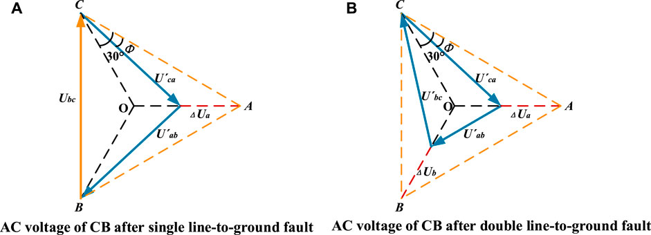
FIGURE 1. AC voltage of converter bus after an unbalanced short circuit. (A) AC voltage of CB after single line-to-ground fault. (B) AC voltage of CB after double line-to-ground fault.
Therefore, the zero-crossing phase shift of the commutating voltage can be formulated as:
At the moment of the fault, the converter transformer ratio remains unchanged, thus the percentage of the commutation voltage drop and that of the voltage drop at the CB are the same. Therefore, the extinction angle of each converter valve at the moment of phase A to ground short-circuit is:
According to (8), when a single-phase to ground short-circuit fault happens, the corresponding converter extinction angle γi reaches the minimum value. When the corresponding converter extinction angle γi ≤ γmin, CF will happen at the converter station of DC i.
Double Line-To-Ground Fault and Line-To-Line Fault
The fault conditions for a double line-to-ground fault occurring on phase A and B of Bus j can be written as:
The Equation 9 can be reduced as:
where k = Zjj(1)Zjj(2) + Zjj(1)Zjj(0) + Zjj(2)Zjj(0).
As is shown in Figure 1B, the phase voltage of phase C remains unchanged after a double line-to-ground fault happens,; the drop voltages and angle changing of phase A are equal to phase B. Substitute (10) into (10) and (11), the voltage variations of phase A at CB i is:
According to the peculiarity of the parallel triangle, after a double line-to-ground fault, the line-to-line voltage between phase A and phase B is:
Furthermore, it can be concluded from Figure 1B that the angle of U’ab is not changed and the relationship of size between each line-to-line voltage is:
Accordingly, the extinction angle γV1,V4 which is related to
The fault conditions for a line-to-line fault occurring on phase A and B can be represented as:
Like single line-to-ground faults and double line-to-ground faults, substitutes Eq. 9 into 2 and 3, the voltage variations of phase A and phase B of CB i by line-to-line fault can be formulated as:
When the line-to-line fault occurs in the AC system, the relationship of the voltage phasor of CB is similar to the phasor which has occurred after a double line-to-ground fault, as is shown in Figure 1B. Using the same process as in Single Line-To-Ground Fault, the line-to-line voltage between phase A and phase B can be formulated as Eq. 12, and the extinction angle can also be formulated by an equation.
When the double line-to-line fault or line-to-line fault occurs at bus j, the extinction angle γV1,V4 of the corresponding converter at CB i can be calculated by Eqs. 11–14. CF will happen at the converter which is connected with CB i while γj ≤ γmin. This serves as a criterion of CF in detecting the line-to-line fault.
The Demarcation of the Critical Failure Impedance Boundaries
In a multi-infeed HVDC system which contains n buses and k HVDC systems, given static models of generators, transmission lines, transformers, loads, and HVDC systems, the steps of demarcating the critical failure impedance boundaries are as follows:
1) Solve AC/DC network load flow and calculate the voltage of each bus.
2) Create the impedance matrix of the system.
3) Calculate extinction angles γ (γ1, γ2 … γk) of every converter of the multi-infeed HVDC system in different fault conditions. To improve the computational efficiency, when the unbalanced fault happened on bus Bi, only γV1,V4 (γ1V1,V4, γ2V1,V4… γmV1,V4) which corresponds to the fault phase should be calculated. When a single line-to-ground fault happens, γmV1,V4 could be calculated by Eq. 8. When a double line-to-ground fault happens, γmV1,V4 could be calculated by Eq. 14. When a line-to-line fault happens, γmV1,V4 could be calculated by Eq. 16,
4) Form the bus sets based on the criterion γij ≤ γmin which detects the CF. The bus sets are defined in Eq. 17 as follows:
BTfail-i is the three-phase short circuit fault bus set; when a three-phase short circuit fault occurs on any bus which is included in this bus set, it may cause the CF fault of a DC converter station i. BSfail-i is the single line-to-ground fault bus set when a single line-to-ground fault occurs on any bus which is included in this bus set; it may cause the CF of a DC converter station i. BDfail-i is the double line-to-ground fault bus set when a double line-to-ground fault occurs on any bus which is included in this bus set; it may cause the CF of a DC converter station i. BLfail-i is the line-to-line fault bus set when a line-to-line fault occurs on any bus which is included in this bus set, and it may cause the CF of a DC converter station i.
5) The corresponding critical failure impedance boundaries are drawn on the system topology diagram, and the communication failure area is defined according to the bus set in step 4). The area within the critical failure impedance boundary is defined as the corresponding critical failure impedance region. When the bus in the critical failure impedance area has a three-phase metal short circuit fault or a single line to ground relative to ground fault, it will lead to CF of the corresponding DC system. On the other hand, if a fault occurs on a bus outside the area, it will not result in CF for the corresponding DC system.
Compared with the common method which detects CF utilizing electromagnetic simulation software, the proposed method uses the minimum extinction angle as the criterion and identifies the critical impedance area quickly and accurately through a simple calculation. The identified critical impedance area provides a clear and direct perspective to the system operators of the area where faults will be critical to the DC CF of the DC system. Moreover, it will provide valuable information for system planning and protection design.
Case Studies
In this section, the proposed method of detecting CFs critical impedance boundaries is validated on the IEEE 39-bus. Based on the CIGRE HVDC standard model, the quasi-steady-state model is adopted in the Multi-infeed DC system. Three-infeed HVDC systems are established in the IEEE 39-bus test system. Parameters of the three HVDC systems are listed in Table 1.
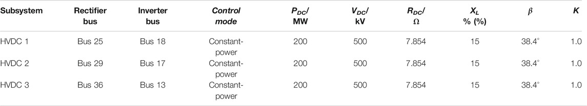
TABLE 1. Parameter of the three-infeed HVDC system.
Following the steps in Case Studies, the extinction angles of the three-infeed HVDC systems in different fault conditions are calculated by substituting the above parameters of the three-infeed HVDC systems into Eqs 8, 14. While the calculated extinction angle is less than γmin, these buses can be put into fault bus sets of different fault type. According to general engineering experience, γmin is taken as 10 in this paper. Take HVDC 1 as example; its three-phase short circuit fault bus set BTfail-1 contains 33 buses, the single line-to-ground fault bus set BSfail-1 contains 12 buses, the double line-to-ground fault bus set BDfail-1 contains 28 buses, and the line-to-line fault bus set BLfail-1 contains 14 buses. The result is consistent with the severity of the bus fault. When a three-phase short circuit fault happens, the voltage drop of CB is largest in four fault conditions. The second largest voltage drop occurs when a double line-to-ground fault happens. However, for a single line-to-ground fault and line-to-line fault, the number of fault bus sets cannot be directly compared and needs to be calculated based on the method proposed in this paper. For example, the number of BSfail-1 is less than the number of BLfail-1, but the number of BSfail-3 is greater than the number of BLfail-3.
In this paper, single line-to-ground faults and line-to-line faults are selected as the focus to analyze the critical failure impedance boundaries. Then, the critical failure impedance boundaries of the three-infeed HVDC system in different fault conditions based on these fault bus sets are demarcated. The detailed results are shown in Figure 2.
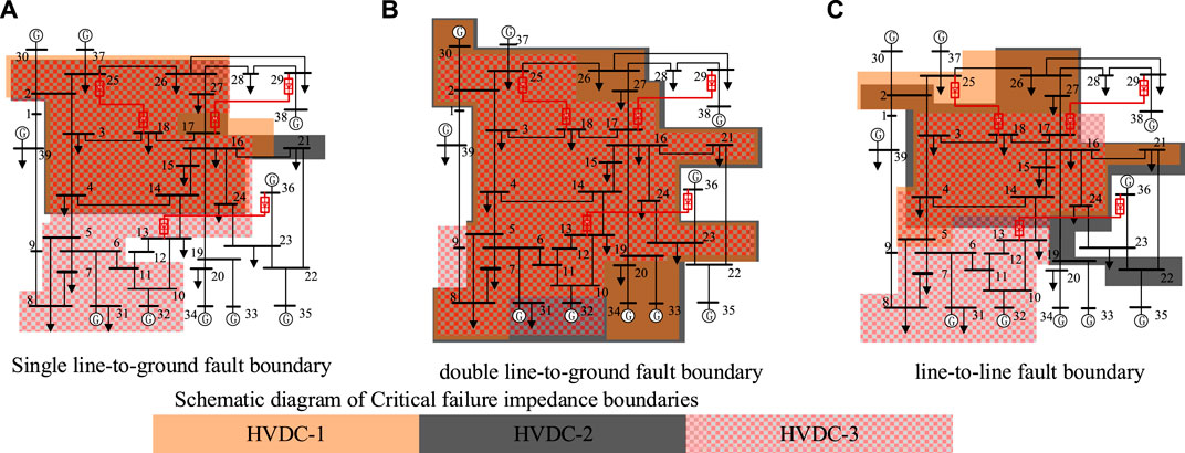
FIGURE 2. Critical failure impedance boundaries of IEEE 39-bus test system. (A) Single line-to-ground fault boundary. (B) Double line-to-ground fault boundary. (C) Line-to-line fault boundary.
As it is shown in Figure 2, some buses are included in the overlap region of different critical failure impedance boundaries. When the corresponding fault occurs on these buses, it may cause CF in more than one HVDC system. Some buses are included in non-overlap regions. When the corresponding fault occurs on these buses, it may cause CF in only one HVDC system. Therefore, the effectiveness of critical failure impedance boundaries can be verified by conducting different types of fault simulations of the buses in the overlap region and some other buses in the non-overlap region. The single line-to-ground fault simulation is conducted on bus 5 and bus 15, the line-to-line fault simulation is conducted on bus 3 and bus 27, and the double line-to-ground fault simulation is conducted on bus 14 and bus 20.
The calculation results are obtained by using the method presented in this paper, while the single line-to-ground fault simulation is conducted on bus 15, γ1,15 = 9.40°, γ2,15 = 8.61°, γ3,15 = 9.72°, they are all less than γmin. According to the calculation results, when a single line-to-ground fault is applied at Bus 15, CF fault will occur on three HVDC systems at the same time, the three inverters will be blocked, and their DC powers drop to 0 MW. The calculation results are the same as the simulation waveforms which are shown in Figure 3A. While the single line-to-ground fault simulation is conducted on bus 5, γ1,5 = 12.96°, γ2,5 = 11.45°, γ3,5 = 8.70°, only γ3,5 is less than γmin. According to the calculation results, when a single line-to-ground fault is applied at Bus 5, the DC powers of HVDC 1 and HVDC 2 drop slightly and CF only occurs on HVDC 3. The calculation results are the same as the simulation waveforms, which are shown in Figure 3B. Therefore, the results of the dynamic simulation are consistent with the results of critical impedance boundaries for a single line-to-ground fault proposed in this paper.
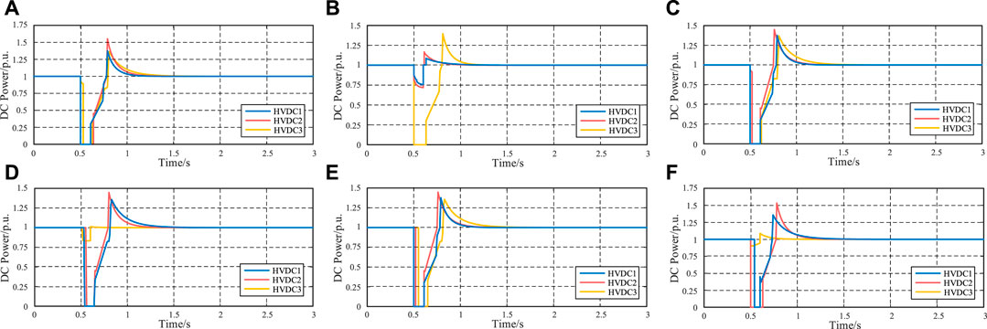
FIGURE 3. Simulation waveform of different fault. (A): DC powers while single line-to-ground fault occurs on Bus 15. (B): DC powers while single line-to-ground fault occurs on Bus 5. (C): DC powers while double line-to-ground fault occurs on Bus 14. (D): DC powers while double line-to-ground fault occurs on Bus 20. (E): DC powers while line-to-line fault occurs on Bus 15. (F): DC powers while line-to-line fault occurs on Bus 27.
The calculation results are obtained by using the method presented in this paper, while the double line-to-ground fault simulation is conducted on bus 14, γ1,14 = 8.94°, γ2,14 = 8.96°, γ3,14 = 8.28°, they are all less than γmin. According to the calculation results, when a double line-to-ground fault is applied at Bus 14, CF fault will occur on three HVDC systems at the same time, the three inverters will be blocked, and their DC powers drop to 0 MW. The calculation results are the same as the simulation waveforms which are shown in Figure 3C. While the single line-to-ground fault simulation is conducted on bus 20, γ1,20 = 9.24°, γ2,20 = 9.30°, γ3,20 = 12.14°, only γ1,20 and γ2,20 are less than γmin. According to the calculation results, when a double line-to-ground fault is applied at Bus 20, the DC powers of HVDC 3 drops slightly and CF only occurs on HVDC 1 and HVDC 2. The calculation results are the same as the simulation waveforms which are shown in Figure 3. Therefore, the results of the dynamic simulation are consistent with the results of critical impedance boundaries for a double line-to-ground fault proposed in this paper.
The calculation results are obtained by using the method presented in this paper, while the line-to-line fault simulation is conducted on bus 3, γ1,3 = 8.04°, γ2,3 = 7.90°, γ3,3 = 9.72°, they are all less than γmin. According to the calculation results, when a line-to-line fault is applied at Bus 15, CF fault will occur on three HVDC systems at the same time, the three inverters will be blocked, and their DC powers drop to 0 MW. The calculation results are the same as the simulation waveforms which are shown in Figure 3E. While the line-to-line fault simulation is conducted on bus 27, γ1,27 = 7.68°, γ2,27 = 7.75°, γ3,27 = 12.14°, only γ1,27 and γ2,27 = 7.75° are less than γmin. According to the calculation results, when a line-to-line fault is applied at Bus 27, the DC powers of HVDC 3 drop slightly and CF occurs on HVDC 1.and HVDC2. The calculation results are the same as the simulation waveforms which are shown in Figure 3F. Therefore, the results of the dynamic simulation are consistent with the results of critical impedance boundaries for a line-to-line fault proposed in this paper.
Conclusion
In this paper, a region boundaries’ determination method for critical commutation failures in multi-infeed HVDC systems is proposed with consideration of unbalanced short circuit faults. A criterion of critical extinction angle is put forward. Numerical simulation results on the modified IEEE 39 bus system demonstrate that the presented method manages to identify the boundaries of the critical commutation failures. Compared with the actual power grid operation, the method presented in this paper is a programmatic calculation method and the results are more rigorous. The calculated boundaries of commutation failures will be larger than the actual boundaries.
Data Availability Statement
The original contributions presented in the study are included in the article/Supplementary material, further inquiries can be directed to the corresponding author.
Author Contributions
GL instructed and proposed the methodology used in this paper. SZ conceptualized and implemented this study, and wrote the original draft. SL dedicated his time to validate the method. XCL and XTL assisted in the conceptualization, investigation, and data.
Conflict of Interest
The authors declare that the research was conducted in the absence of any commercial or financial relationships that could be construed as a potential conflict of interest.
The reviewer YL declared a shared affiliation with one of the authors, SZ, to the handling editor at time of review.
References
Guo, C., Liu, Y., Zhao, C., Wei, X., and Xu, W. (2015). Power component fault detection method and improved current order limiter control for commutation failure mitigation in HVDC. IEEE Trans. Power Deliv. 30 (3), 486–495. doi:10.1109/tpwrd.2015.2411997
Li, G., Zhang, S., and Jiang, T., Chen, H., and Li, X. (2017). “A method of detecting commutation failure in multi-infeed HVDC systems based on critical failure impedance boundary. “in IEEE Power & Energy Society General Meeting, Chicago, IL, July 16–20, 2017, 1–5.
Mirsaeidi, S., Dong, X., Tzelepis, D., Said, D. M., Dysko, A., and Booth, C. (2018). A predictive control strategy for mitigation of commutation failure in LCC-Based HVDC systems. IEEE Trans. Power Elect. 34 (1), 160–172. doi:10.1109/TPEL.2018.2820152
Wang, F., Liu, T. Q., and Li, X. Y. (2017). Decreasing the frequency of HVDC commutation failures caused by harmonics. IET Power Elect. 10 (2), 215–221. doi:10.1049/iet-pel.2016.0230
Wang, Z., Liu, X., Li, L., and Yang, Y. (2017). Boundary conditions of commutation failure in multi-infeed HVDC systems. Trans. China Electrotech. Soc. 32 (10), 12–19.
Wang, J., Huang, M., Fu, C., Li, H., Xu, S., and Li, X. (2019). A new recovery strategy of HVDC system during AC faults. IEEE Trans. Power Deliv. 34 (2), 486–495. doi:10.1109/tpwrd.2019.2892410
Wang, Q., Zhang, C., Wu, X., and Tang, Y. (2019). Commutation failure prediction method considering commutation voltage distortion and DC current variation. IEEE Access 7, 96531–96539. doi:10.1109/access.2019.2929301
Wei, Z., Yuan, Y., Lei, X., Wang, H., Sun, G., and Sun, Y. (2014). Direct-current predictive control strategy for inhibiting commutation failure in HVDC converter. IEEE Trans. Power Syst. 29 (5), 2409–2417. doi:10.1109/tpwrs.2014.2302010
Xiao, H., Li, Y., Zhu, J., and Duan, X. (2016). Efficient approach to quantify commutation failure immunity levels in multi‐infeed HVDC systems. IET Gene., Transm. Distri. 10 (4), 1032–1038. doi:10.1049/iet-gtd.2015.0800
Xue, Y., Zhang, X., and Yang, C. (2016). Elimination of commutation failures of LCC HVDC system with controllable capacitors. IEEE Trans. Power Syst. 31 (4), 3289–3299. doi:10.1109/tpwrs.2015.2491784
Xue, Y., Zhang, X. P., and Yang, C. (2018). Commutation failure elimination of LCC HVDC systems using thyristor-based controllable capacitors. IEEE Trans. Power Deliv. 33 (3), 1448–1458. doi:10.1109/tpwrd.2017.2776867
Yao, W., Liu, C., Fang, J., Ai, X., Wen, J., and Cheng, S. (2020). Probabilistic analysis of commutation failure in LCC-HVDC system considering the CFPREV and the initial fault voltage angle, IEEE Trans. Power Deliv. 35 (2), 715–724. doi:10.1109/tpwrd.2019.2925399
Keywords: commutation failure, muti-infeed HVDC, extinction angle, three-phase short circuit fault, unbalanced short circuit fault
Citation: Li G, Zhang S, Li S, Liu X and Liu X (2021) Determining Region Boundaries of Critical Commutation Failures in Multi-Infeed HVDC Systems Under Unbalanced Short Circuit Faults. Front. Energy Res. 9:635010. doi: 10.3389/fenrg.2021.635010
Received: 29 November 2020; Accepted: 09 February 2021;
Published: 26 April 2021.
Edited by:
Chao Long, Cranfield University, United KingdomReviewed by:
Yang Li, Northeast Electric Power University, ChinaChen Liang, Nanjing University of Information Science and Technology, China
Shaoyan Li, North China Electric Power University, China
Copyright © 2021 Li, Zhang, Li, Liu and Liu. This is an open-access article distributed under the terms of the Creative Commons Attribution License (CC BY). The use, distribution or reproduction in other forums is permitted, provided the original author(s) and the copyright owner(s) are credited and that the original publication in this journal is cited, in accordance with accepted academic practice. No use, distribution or reproduction is permitted which does not comply with these terms.
*Correspondence: Song Zhang, emhhbmdzb25nbmVlcHVAYWxpeXVuLmNvbQ==