 Alexis Maurel1,2,3*
 Hyeonseok Kim1,3Roberto Russo1,3,4Sylvie Grugeon1,3
 Michel Armand1
 Stephane Panier2
 Loic Dupont1,3,5*
- 1Laboratoire de Réactivité et de Chimie des Solides, Université de Picardie Jules Verne, Amiens, France
- 2Laboratoire des Technologies Innovantes, Université de Picardie Jules Verne, Amiens, France
- 3Réseau français sur le stockage électrochimique de l’énergie, Amiens, France
- 4Department Electric Equipment Laboratory (LME), EDF R&D, Morêt-Sur-Loing, France
- 5Plateforme de Microscopie Électronique (PME) de l'Université de Picardie Jules Verne, Amiens, France
This article focuses on the development of polylactic acid– (PLA-) based thermoplastic composite filament for its use, once 3D printed via thermoplastic material extrusion (TME), as current collector at the negative electrode side of a lithium-ion battery or sodium-ion battery. High electronic conductivity is achieved through the introduction of Ag-coated Cu charges, while appropriate mechanical performance to allow printability was maintained through the incorporation of poly(ethylene glycol) dimethyl ether average Mn ∼ 500 (PEGDME500) as a plasticizer into the PLA polymer matrix. Herein, thermal, electrical, morphological, electrochemical, and printability characteristics are discussed thoroughly. While Ag-Li alloy formation is reported at 0.1V upon cycling, its use with active materials such as Li4Ti5O12 (LTO) or Li2-terephthalate (Li2TP) operating at a plateau at higher potential is demonstrated. Furthermore, its ability to be used with negative electrode active material of sodium-ion battery technology in a wide potential window is demonstrated.
Introduction
Over the last few years, numerous studies dedicated to the lithium-ion battery (LIB) 3D printing have been published in the literature (Pang et al., 2019; Browne et al., 2020; Cheng et al., 2020; Costa et al., 2020; Egorov et al., 2020; Gulzar et al., 2020; Lyu et al., 2020; Maurel et al., 2020c; Yang et al., 2020; Yang and Fan, 2020; Zeng et al., 2020; Zhang et al., 2020). This trend can be simply justified by the new design freedom offered by the innovative additive manufacturing (AM) processes. Indeed, thanks to such cutting-edge technology, it is now possible to imagine the development of LIB three-dimensional (3D) architectures reported to increase the electroactive surface area greatly, allowing the Li+ diffusion towards two or three dimensions and thus improving the final electrochemical performance of the battery in terms of specific capacity and power (Trembacki et al., 2019; Maurel et al., 2020b); on the other hand, conventional 2D LIB architectures of the positive electrode, separators, negative electrode, and current collector are stacked or rolled (parallel plates configuration), previously reported to allow only Li+ diffusion in 1D. While 3D LIB structures, originally proposed by Long et al. (Long et al., 2004; Long et al., 2020), were extensively developed independently through traditional techniques such as electrodeposition, the assembly of both electrodes manually was reported to be particularly complex due to the irregular electrode surfaces causing short circuits (Taberna et al., 2006). As an innovative alternative and to prevent this last issue, AM appears as a unique route to obtain such complex interlaced electrode architectures. Additionally, such a technique also opens the way towards topological optimization by directly introducing the energy storage device within the whole available free space of the object.
Among the various offered 3D printing processes, thermoplastic material extrusion (TME), also commonly called fused deposition modeling (FDM), was investigated recently due to its undeniable advantage allowing the elaboration of a complete LIB in one-single step without requiring any extra postprocesses compared to other AM techniques such as direct ink writing (DIW) or stereolithography apparatus (SLA) that generally require freeze-drying, debinding, and/or sintering (Sun et al., 2013; Fu et al., 2016; Cohen et al., 2018). A classical TME printer (Figure 1) is usually fed with a 1.75mm diameter thermoplastic filament that is heated few degrees above its melting temperature to be selectively deposited through a nozzle. Being computer-controlled, the latter is indeed moved so as to build the final 3D object layer after layer. Commercial desktop TME 3D printers have a layer thickness resolution of about 150μm for the first layer and down to 50μm for the subsequent layers.
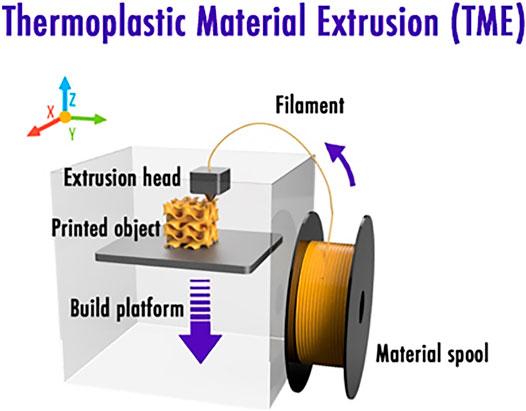
FIGURE 1. Thermoplastic material extrusion 3D printing scheme.
Starting from 2017, various groups initiated the development of bespoke composite 3D printable filaments, specifically developed to print components of a classical LIB: positive electrodes (PLA/LiFePO4 (Ragones et al., 2018; Maurel et al., 2019), PP/LiFePO4 (Maurel et al., 2020), PLA/LMO (Reyes et al., 2018)), negative electrodes (PLA/graphite (Maurel et al., 2018; Maurel et al., 2019), PLA/LTO (Ragones et al., 2018; Reyes et al., 2018)), separator (PLA/SiO2 (Maurel et al., 2019)) and solid polymer electrolyte (PEO/LiTFSI (Maurel et al., 2020a), PLA/PEO/LiTFSI (Ragones et al., 2019)). In 2018, an important milestone was reached in the field as our group (Maurel et al., 2018) reporting for the first time that the introduction of a thoroughly chosen plasticizer helps to increase the number of charges within the composite filament considerably. Indeed, highly loaded PLA/graphite (Maurel et al., 2018) and PLA/LiFePO4 (Maurel et al., 2019) filaments with up to 62wt% of active material were, respectively, formulated as negative and positive electrodes. This was made possible through the introduction of poly(ethylene glycol) dimethyl ether average Mn ∼ 500 (PEGDME500) as a plasticizer to enhance its flexibility. After optimization by introducing a conductive additive within the composite, a negative electrode (Maurel et al., 2018) (tested in a half-cell configuration using 1M LiPF6 in ethylene carbonate and diethyl carbonate as liquid electrolyte) depicted a reversible capacity of 200mAhg−1 of active material (99mAhg−1 of the total composite or also to 154.6mAh cm−3) at current density of 18.6mAg−1 (C/20) after six cycles and 140mAhg−1 of active material (69mAhg−1 of the total composite or also 108.2mAhcm−3) at current density of 37.3mAg−1 (C/10). Likewise, the optimized 3D printed positive electrode developed by our group (Maurel et al., 2019) exhibited reversible capacity values of about 87mAhg−1 of active material (43mAhg−1 of the total composite or also to 77mAhcm−3) at current density of 8.5mAg−1 (C/20), 45mAhg−1 of active material (22mAhg−1 of the total composite or also to 40mAhcm−3) at a current density of 17mAg−1 (C/10), and 22mAhg−1 of active material (11mAh g−1 of the total composite or also to 20mAhcm−3) at a current density of 34mAg−1 (C/5).
While the last efforts (Maurel et al., 2020c) were exclusively focused on the development of 3D printable composite thermoplastic filaments for the positive electrode, negative electrode, and separator and solid polymer electrolyte, it is now required to focus on the last piece of the LIB puzzle: the development of a 3D printable composite current collector filament, specially designed for LIB application. Being the direct connection between the electrode and the external circuit, current collectors must exhibit electronical conductivity as high as possible and inertness towards the electrode materials and the electrolyte. Hence, metal foils are usually employed in commercial LIB. Thus, the metal selection for each current collector should be chosen in good agreement with their own electrochemical stability window. Copper foil is generally employed as current collector at the negative electrode as it appears to be electrochemically stable down to 0V vs. Li/Li+ (Myung et al., 2011). On the other hand, aluminum foil current collector (cheaper and lighter) is used at the positive electrode as it is stable at higher potential due to the AlF3 passivating layer created thanks to the presence of LiPF6 salt (Forestier et al., 2016), thus blocking subsequent aluminum oxidation. Al is not used at the negative electrode as an Li–Al alloying process starts when potential is close to ∼0.3V vs. Li/Li+ (Myung et al., 2011). Practically, extended corrosion of current collectors under cycling can lead to an increase of the cell overall resistance causing capacity fading. In extreme cases, it could even induce short circuit, affecting the device’s safety. Finally, it is important to mention that metallic foil current collectors, usually serving as support for the coated electrodes, can generate some adhesion issues due to their smooth surface. Indeed, metallic foils can unfortunately cause the active material particles detachment reported to be particularly problematic for flexible electrode manufacturing. Hence, carbon-based materials or conducting polymers may be potential candidates for flexible current collectors (Singh et al., 2012).
Destined here as a preliminary work, the mission of this research was to study the possibility of introducing copper particles within a PLA polymer matrix to develop a current collector (negative electrode side) composite 3D printable filament for LIB or SIB applications. As depicted hereafter, film, filament, and 3D printed discs were characterized by means of differential scanning calorimetry (DSC), electrochemical impedance spectroscopy (EIS), galvanostatic cycling with potential limitation (GCPL) technique, and scanning electron microscopy (SEM). In order to improve the electronic conductivity, the introduction of a silver coating on top of the copper particles by electroless deposition and its impact on the final composite current collector were investigated. By means of electrochemical characterization, the lower limit of the working potential window of the optimized current collector composition was then studied. Subsequently, adequate electroactive materials were proposed.
Experimental
Materials
Polylactic acid (PLA 4032D) pellets were provided by NatureWorks, United States. Dichloromethane (DCM) solvent was supplied by VMR Chemicals, United States. Copper particles (Cu) (particle size between 10 and 25µm) purchased from Sigma Aldrich, Europe, were used as conductive material for the current collector of the LIB. Poly(ethylene glycol) dimethyl ether average Mn ∼ 500 (PEGDME500), H2SO4 sulfuric acid (97% concentration), AgNO3 silver nitrate (99.9% concentration) (NH4)2CO3 ammonium carbonate (99% concentration), and NH4OH ammonium hydroxide (28% concentration) were all purchased from Sigma Aldrich, Europe. Terephthalic acid (98% concentration) powder was provided by Alfa Aesar, Thermo Fischer Scientific, United States. LiOH∙H2O (98%) powder was purchased from Sigma Aldrich, Europe. Li2-terephthalate (Li2TP) was synthesized using the procedure reported by Armand et al. (Armand et al., 2009). Li4Ti5O12 (LTO) was supplied by MTI Corporation, United States. Carbon Black Timcal Super-P (SSA: 62m2g−1) was supplied by Sigma Aldrich, USA. Hard carbon (HC) powder (2.8m2g−1) was provided by GEM Holding Corporation, Japan.
Deposition of an Ag Coating on Top of the Cu Powder
Silver was coated on copper through the redox process in order to prevent the oxidation of the surface of copper and enhance the electronic conductivity. The first step consisted of introducing 50g of the copper powder in a sulfuric acid solution (sulfuric acid 20ml + diluted water 200ml) for 2min so as to remove oxide layers Eq. (1).
According to Lee et al., 2.7nm of oxide layer can be etched by diluted H2SO4 with a volume ratio of H2SO4 to water of 1:20 for 2min (Lee et al., 2013). The resulting neat copper powder was then washed until the pH of copper reached the pH of DI water and finally introduced in 100ml of DI water. On the other hand, 7.85g of silver nitrate, 100g of ammonium carbonate, and aqueous ammonia were mixed together in 100ml of distilled water to create a silver complex solution. Lastly, the silver complex solution was gradually added to copper powder suspension over a period of 5min at room temperature. The mixture of copper and silver complex solution was stirred further for an hour to create a silver shell on top of the copper powder. As reported in the literature (Hai et al., 2006), the activated copper on the surface of copper powder is displaced with silver ion according to the following Eq. (2):
It is worth mentioning that the pH of the silver complex solution is reported to have a strong impact on the deposition rate of Ag onto Cu, surface morphology, roughness, crystallinity, polarization, and impedance behavior. A mixture of aqueous ammonia and ammonium carbonate solution is used in this experiment (NH4+/NH3, pKa = 9.2). Large amounts of the ammonia water and ammonium carbonate compound are required with regard to the amount of silver nitrate because ammonia also acts as a complexing agent. Furthermore, the ideal molar ratio of ammonium carbonate to ammonia solution is reported to be from 0.1 to 3 (Koto et al., 1987). If the molar ratio is out of range, it has a negative effect on the conductivity of the coating layer. In this experiment, a molar ratio of 7.8 : 7.2 (ammonium carbonate to ammonia) was employed.
Film Formulation
After complete dissolution of the polymer matrix in a solvent (DCM at ambient temperature for PLA) with a weight ratio polymer matrix/solvent 1:10, PEGDME500 plasticizer was introduced to the mixture (PLA: PEGDME500 wt% 100:40). The resulting slurry was then mixed for 30min prior to the introduction of the conductive Cu-based powder (polymer matrix:Cu-based powder wt% 10:90) and stirred magnetically for 1h. For each sample, the prepared slurries were deposited onto a glass substrate by tape casting. After drying under ambient environment for 2h, samples were further dried under vacuum for 24h; in the case of LTO, another drying step was added, 4h under vacuum at 110°C. The obtained free-standing 100 and 250-μm-thick films then undergo further characterization experiments. Thicker film samples were employed for EIS measurements and for performing SEM imaging, while thinner films were characterized by DSC and through galvanostatic electrochemical tests.
Composite Filaments Formulation
As depicted in our previous articles (Maurel et al., 2018; Maurel et al., 2019; Maurel et al., 2020a; Maurel et al., 2020b), a Filabot Original extruder provided by Filabot Triex LLC, United States, was fed consistently with 3 × 3mm composite film pieces to get standard 1.75mm diameter 3D printing filaments. Extruder temperature was set about 20°C higher than the melting temperature of the composite film deduced from DSC. The resulting filament was subsequently rolled around a spool by means of a Filabot spooler (Filabot Triex LLC, United States). The extruder was methodically cleaned with pure PLA polymer matrix before extrusion of each sample. Current collector filaments were then kept in a suitable storage environment with low humidity and at low temperature to avoid the evaporation of plasticizer.
Thermoplastic Material Extrusion Printing
Current collector 3D discs (11mm diameter, 200µm or 1mm thick) were designed by means of Autodesk Fusion 360 software, after which they were divided into 100µm thick 2D slices using PrusaSlicer software and printed by a Prusa MK3S 3D printer (Prusa Research, Czech Republic) to perform further EIS and cyclic voltammetry. Nozzle ordinary input and output diameters of 1.75 and 0.4mm, respectively, were employed. The highest resolution in the Z direction is 200µm for the first layer and 50µm for the following. The nozzle temperature was set 20°C higher than the melting temperature of the composite film and the fan settings were set to 100%. Bed temperature was set to 60°C to favor the adherence of the first printed layer. Prior to printing each sample, the nozzle was purged thoroughly by printing a 2cm3 purge cube with the corresponding filament.
Differential Scanning Calorimetry (DSC)
Thermal characterization of films, filaments, and 3D printed discs was carried out by means of a DSC204F1 supplied by NETZSCH-Gerätebau GmbH, Germany. All prepared samples were characterized between −60 and 300C at a heating rate of 10Cmin−1 under argon atmosphere (50mlmin−1), using about 10mg of sample of each composition. Heat flow data from the first heating operation were recorded.
Electron Microscopy
By means of a FEI Quanta200F (Thermo Fisher Scientific, United States) SEM in high vacuum mode, the material dispersion and sample homogeneity were investigated. The secondary and backscattered images were recorded with a 5kV acceleration voltage. Energy-dispersive X-ray spectroscopy (EDS) elementary maps (Cu, Ag, O) were recorded at 20kV.
Electrical Conductivity Characterization
EIS tests were achieved using an MTZ-35 frequency response analyzer and an intermediate temperature system (ITS) supplied by BioLogic, France. The exact same procedure as the one reported in our previous work was followed (Maurel et al., 2018). Inductive phenomena from cables were compensated by performing calibration of the empty ITS with the same cables. Current collector films (transversal section, 250μm thick) and filament (longitudinal section, 2mm long) were subsequently introduced into a controlled environment sample holder (CESH) to perform AC impedance measurement under air at temperatures varying from 20 to 60°C (upon heating in steps of 5C). An excitation voltage of 10mV, a frequency range of 20–0.05Hz (20 points per decade and 10 measurements per point), and a soak time of 15min were applied here. Electronic conductivities and activation energy were deduced from the Nyquist and phase Bode plots of the complex impedance. Conductivities were calculated from Eq. (3).
where d is the pellet thickness, A is the pellet surface area, and R is the respective resistances determined from the Nyquist and Bode plots.
Electrochemical Characterization
Inside an argon-filled glovebox (H2O < 0.1ppm, O2 < 0.1ppm), Swagelok-type cells were assembled. Metallic lithium and metallic sodium were used as counter/reference electrodes for half-cells, while Ag-coated Cu–based samples were used as working electrodes. The fiberglass separator was provided by Whatman, GE Healthcare, United States. A 150 µl of 1M LiPF6 in ethylene carbonate and diethyl carbonate (EC:DEC 1:1 weight ratio) and 150 µl of 1M NaPF6 in ethylene carbonate and dimethyl carbonate (EC:DMC 1:1 weight ratio) were used as an electrolyte, respectively, and supplied by Merck KGaA, Germany. Cells were galvanostatically discharged (lithiation or sodiation) and charged (delithiation or desodiation) at a current of 50μA, between 0.005 and 1.5V (vs. Li/Li+ and vs. Na/Na+) by means of a BCS-805 (BioLogic, France) to see if an alloy with Li or Na metal was created. On the other hand, electrochemical tests using LTO film (LTO, carbon black, PVdF-HFP in a weight ratio of 65:14:21) deposited on top of the produced Ag-coated Cu current collector were performed at a current of 45.5μA (C/20), 91μA (C/10) and 182μA (C/5), between 1.3 and 2.0V (vs. Li/Li+). Tests using Li2TP powder (Li2TP, carbon black, in a weight ratio of 70:30 thoroughly mixed in a mortar) deposited on top of the Ag-coated Cu produced current collector were performed at a current of 1.161mA (C/5) and 2.903mA (C/2), between 0.5 and 2.0V (vs. Li/Li+). Finally, tests using HC powder (2.8m2/g) deposited on top of the produced Ag-coated Cu current collector were performed at a current of 50μA, between 0.005 and 1.5V (vs. Na/Na+). Electrochemical tests were performed at 20°C.
Results and Discussions
Neat Cu-Based Current Collector Film
The first part of this study was dedicated to the formulation of a neat Cu-based current collector composed of PLA/Cu/PEGDME500, wt% 9.6/86.5/3.8 or vol% 36.6/46.0/17.3. This particular composition was chosen as it corresponds to the maximum amount of charges (here, Cu) that can be added within a polymer matrix without compromising the printability of the resulting composite filament as depicted in our previous study (maximum limit of 50 vol%) (Maurel, 2020). For this particular sample composition, the achieved Nyquist and Bode curves were in accordance with an electronic conductor classical behavior as the Nyquist plot portrayed only Z’ real part, while |Z| magnitude remained steady for all frequencies. While an increase of temperature causing conductivity values to decrease is usually exhibited by pure metals, here, due to its composite nature, the sample rather exhibits a semiconductor-type behavior as the electrical conductivity is rising with temperature, as shown in Figure 2. Here, an activation energy value of 0.678meV was estimated for the composite sample containing neat Cu. Furthermore, it appears that this film sample is very poorly conductive (4.2 × 10⁻¹⁰Scm−1 at 20°C and about 1.0 × 10⁻⁸Scm−1 at 60°C). Hence, its use as current collector in a LIB or SIB is highly compromised. This trend clearly corroborates the SEM/EDS observations that highlighted the presence of a CuO insulating layer on the surface of the Cu particles (Figure 2). Such a layer has been generated spontaneously upon storage. Since such a CuO passivation layer is known to be highly insulating and, as a metal oxide, is electrochemically reactive towards lithium through the so-called conversion reaction (Grugeon et al., 2001), a protocol was established to dissolve it and subsequently depose a homogeneous Ag layer on the surface of the Cu particles. This was done with a view to prevent surface copper from oxidation and enhance the electronic conductivity.
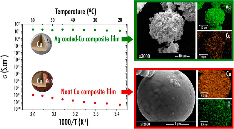
FIGURE 2. Arrhenius plots of the electrical conductivity for film current collector samples containing neat copper and silver-coated copper and their respective SEM image and element distribution map (Ag, Cu, and O) obtained by Energy Dispersive X-ray Spectroscopy (EDS).
Following the deposition of Ag on the surface of the Cu particles, the resulting powder was thus characterized via SEM/EDS. Noticeably, as depicted in Figure 2, it appears that the aforementioned protocol worked properly as Ag was clearly identified on the Cu particles surface. Deposit morphology is particularly interesting as Ag was precipitated as beads (∼1µm diameter). Nonetheless, it is worth mentioning that further thorough TEM experiments are still required in the future to precisely determine the thickness of the Ag layer.
Similar to what was achieved previously for the sample containing neat Cu, the conductivity of the composite film PLA/Ag-coated Cu/PEGDME500 (wt% 9.6/86.5/3.8) was investigated through EIS. As displayed in Figure 2, the sample containing Ag-coated Cu powder was shown to exhibit a drastically higher conductivity reaching 11.3Scm−1 at 20°C (multiplied by 2.8 × 10¹⁰ times in comparison with composite film sample containing neat Cu), thus paving the way towards the preparation of a highly conductive current collector filament. Here again, the sample exhibits a semiconductor-type behavior with an activation energy value of 0.071meV.
Ag-Coated Cu–Based Current Collector 3D Printable Filament
The elaboration of a composite filament, here comprising PLA/Ag-coated Cu/PEGDME500 (wt% 9.6/86.5/3.8), specially designed to be used as a current collector within a LIB or SIB was initiated. Analogous to what was done in our previous studies regarding electrodes (Maurel et al., 2018; Maurel et al., 2019; Maurel et al., 2020b), separator (Maurel et al., 2019) or solid polymer electrolyte (Maurel et al., 2020a), the sample was first of all characterized via DSC. From this experiment, as shown in Figure 3A, serving here as a reference, neat PLA displays an endothermal peak related to the melting temperature (Tm) at 146C and a sharp peak corresponding to the glass transition (Tg) appearing at 63C. Instead, through the introduction of such a high number of charges (Ag-coated Cu particles) within the polymer matrix, the endothermal peak corresponding to the melting temperature was slightly shifted to a lower temperature (emerging at 142C), while Tg was no longer distinctly visible. PEGDME500 melting temperature appeared at about 5°C, while the crystallization temperature of the Ag-coated Cu composite film emerged at 75°C. From these values, it was decided to produce the corresponding filament by fixing the extruder temperature at a slightly higher temperature of 162°C. Based on the work reported by Ragones et al. (Ragones et al., 2019), the percentage of crystallinity of the polymer matrix was calculated using Eq. (4):
where ∆Hm is the value of melting enthalpy, ∆Hc is the crystallization enthalpy, ∆H100 is the enthalpy of the completely crystalline PLA serving here as reference (93.6J/g for PLA (Li et al., 2015; Ragones et al., 2019)), and w is the weight fraction of polymer in the sample. While from the DSC experiments, it was demonstrated that a neat PLA pellet depicts a crystallinity of 42%, here, a crystallinity of about 47% (not considering the plasticizer evaporation) was calculated from the Ag-coated Cu–based film. This value is in good agreement with what was observed previously for PLA/graphite (42% of crystallinity) and PLA/LiFePO4 (45%), with a similar vol% loading of charges (active material/conductive additive) (Maurel, 2020).
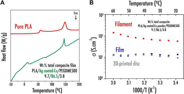
FIGURE 3. (A) DSC curve for neat PLA and the prepared PLA/Ag-coated Cu powder/PEGDME500 film; (B) Arrhenius plots of the electrical conductivity for wt% PLA/Ag-coated Cu powder/PEGDME500 9.7/86.5/3.8 film, filament, and 3D printed disc current collector samples.
Figure 3B exhibits the EIS results of both PLA/Ag-coated Cu/PEGDME500 (wt% 9.6/86.5/3.8) film and filament. The transversal section was characterized by EIS for the film sample, whereas the longitudinal section was rather studied for the filament. The conductivity of filament is improved by 9 times compared with what was obtained for the film. This behavior can be explained by the more homogeneous distribution of the Ag-coated Cu powder within the filament microstructure, as corroborated by SEM. Indeed, as displayed in Figure 4B, during the film formulation, Ag-coated Cu charges tend to sediment by gravity upon solvent evaporation due to their relatively high density, thus forming a composition gradient that ultimately results in a nonhomogenous sample. On the other hand, via extrusion, the resulting sample (Figure 4A) clearly seems homogenous as charges are uniformly dispersed within the PLA matrix.
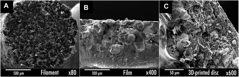
FIGURE 4. Cross-sectional SEM images of the wt% PLA/Ag-coated Cu powder/PEGDME500 9.7/86.5/3.8 (A) filament; (B) film; (C) 3D printed disc.
The electrical resistivity of the Ag-coated Cu/PLA/PEGDME500 filament was then compared with commercially available conductive filaments. Filaments length of 10cm were cut and resistance was measured with a multimeter from both ends. Following the protocol established by the company Multi3D LLC on their website (https://www.multi3dllc.com), silver paste was applied to the ends of the filament before performing the measurement in order to reduce the contact resistance between the probes and the filament. Subsequently, the resistivity values were calculated according to the following Eq. (5):
where ρ is the resistivity of the filament in Ωcm, R is the resistance in Ω,L corresponds to the filament length in cm, and r is the radius of the filament in cm.
After calculations, it appears that the Ag-coated Cu–based filament produced in this work depicts a resistivity of 0.112Ωcm. It is thus much more conductive than commercial filaments produced by Proto-Pasta (4.340Ωcm—PLA/graphite) and Black Magic 3D ( ∼ 0.6Ωcm—PLA/graphene) but less conductive than the commercial Electrifi filament (Multi3D LLC) (resistivity value of about 0.006Ωcm). Hence, the electrical performance could still be optimized through the addition of conductive additives (CSP, CNF, or CNT) or other aspect ratios of Ag-coated Cu additive. On the other hand, from the mechanical standpoint, it is worth mentioning that even if the TME printability of the Ag-coated Cu filament was demonstrated, its printability is still complex due to the introduction of such a high fraction of conductive charges compared with the less conductive commercial Proto-Pasta and Black Magic filaments. Indeed, here, due to the significant number of Ag-coated Cu particles, an accumulation of particles occasionally occurs within the nozzle head through printing, thus blocking the 0.4mm nozzle outlet. In order to find the best compromise between electrical performance and printability, future studies may be focused on the development of 3D printing filament via coextrusion. Therefore, charges could be concentrated in the central part of the filament while a thin coating of pure polymer matrix would wrap it. Such coextruded filament would undoubtedly be much easier to print as it would considerably prevent nozzle clogging issues.
Ag-Coated Cu–Based Current Collector 3D Printed Disc
The previously prepared Ag-coated Cu–based filament was subsequently introduced as a material source to feed the FDM 3D printer. The resulting 3D printed current collector discs were finally obtained and their electrical capability to be used as current collector for the negative electrode was examined (Figure 5). The first step consisted in testing the 3D-printed Ag-coated Cu/PLA/PEGDME500 disc vs. lithium metal directly. From this experiment, as depicted in Figure 6A representing the first discharge profile, an endless plateau corresponding to the alloying process occurring between Ag and Li metal was observed at 0.08V. Consequently, the use of such Ag-coated Cu–based current collector is unfortunately strictly limited to higher potentials, thus limiting its application to only certain types of active material such as LTO or organic materials such as Li2TP, depicting a plateau at 1.5 and 0.7V, respectively. After depositing LTO film (Figure 6B) or Li2TP powder (Figure 6C) on top of the Ag-coated Cu/PLA/PEGDME500 current collector disc, capacity retentions of both samples were recorded. At the tested current densities (C/20, C/10, and C/5), LTO film (Figure 6B) depicts capacity retention very close to the theoretical capacity of the active material (175mAhg−1). This trend here confirms the ability of the Ag-coated Cu/PLA/PEGDME500 sample to be used as current collector. On the other hand, a cell containing Li2TP powder as active material was also tested. As exhibited in Figure 6C, when deposited on top of the Ag-coated Cu/PLA/PEGDME500 3D printed disc, the organic material depicts capacity retention very close to the one achieved without the current collector. It is worth mentioning that, here, the relatively poor electrochemical properties (in comparison with what was achieved in the literature (Armand et al., 2009) using similar active material (up to 300mAhg−1)) are only related to the active material/carbon black ratio and mixing process that still requires to be optimized.
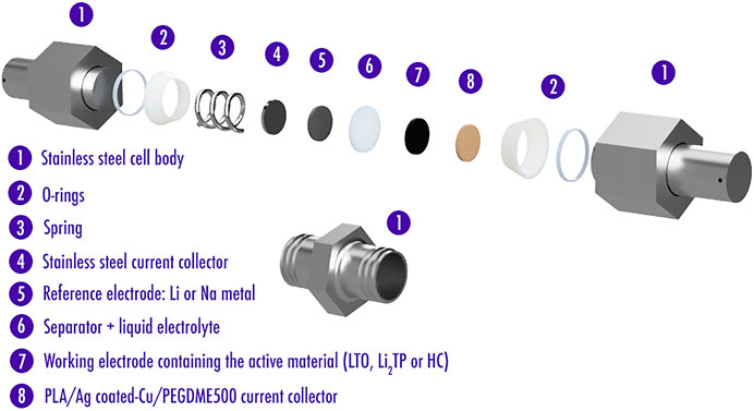
FIGURE 5. Swagelok-type cells assembly for further electrochemical experiments.
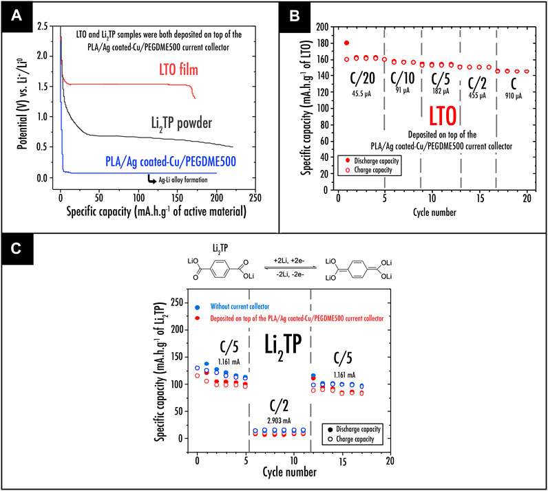
FIGURE 6. (A) First discharge profile; (B) capacity retention plots at different C-rate for the LTO film (LTO, carbon black, and PVdF-HFP in a weight ratio of 65:14:21) deposited on top of the 3D printed PLA/Ag-coated Cu/PEGDME500 current collector; (C) capacity retention plots at different C-rate for the Li2TP powder preparation (Li2TP and carbon black, in a weight ratio of 70:30 thoroughly mixed in a mortar) deposited on top of the 3D printed PLA/Ag-coated Cu/PEGDME500 current collector.
Furthermore, the application of the Ag-coated Cu/PLA/PEGDME500 sample as current collector within a sodium-based battery technology was also considered. First, the 3D printed disc was tested vs. sodium metal. As depicted in Figure 7A representing the first discharge profile of the Ag-coated Cu/PLA/PEGDME500 sample vs. sodium metal, no plateau corresponding to the alloying process between Ag and Na metal was observed. In this context, from the electrochemical point of view, it appears that the Ag-coated Cu–based current collector developed in this work can be extensively employed on the negative electrode side for a wide range of active materials. This was indeed confirmed through testing a cell in which HC powder was deposited on top of the Ag-coated Cu/PLA/PEGDME500 current collector sample. As shown in Figures 7A,B a reversible capacity of 269mAhg−1 of active material after ten cycles was exhibited.
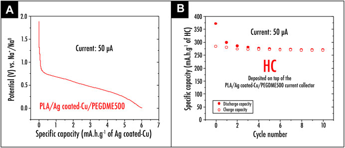
FIGURE 7. (A) First discharge profile of the Ag-coated Cu/PLA/PEGDME500 sample versus sodium metal; (B) capacity retention plot for the HC powder deposited on top of the 3D printed PLA/Ag-coated Cu/PEGDME500 current collector.
While a polar polymer matrix (PLA) was introduced in this preliminary study, it must be replaced in the future by a nonpolar and inert matrix such as polyolefin (PP or PE). Indeed, as demonstrated in our previous study (Maurel et al., 2020b), PLA swells when soaked in the liquid electrolyte; thus, it is suspected to have a detrimental effect on electronic conductivity. While this behavior is particularly interesting for a separator, it will significantly limit the long-term mechanical performance of a current collector.
Conclusion
In this work, the development of an Ag-coated Cu polylactic acid (PLA) thermoplastic composite filament for its use, once 3D printed via TME, as current collector at the negative electrode side of a classical LIB or sodium-ion battery, has been demonstrated. The high electronic conductivity was achieved here through the deposition of Ag coating on top of Cu powder (after previous etching), while the filament mechanical performance was improved through the incorporation of poly(ethylene glycol) dimethyl ether average Mn∼500 (PEGDME500) as a plasticizer into the PLA polymer matrix. While printability of the resulting bespoke filament still remains complex due to its composite nature (up to 46 vol% of charges), its electrical and electrochemical ability making it suitable for use as current collector was established. Although the current collector developed in this work was shown to form an alloy with lithium metal at 0.08V, its use with active materials such as LTO or Li2TP depicting a plateau at higher potentials was confirmed. Finally, its wide use as current collector at the negative electrode side was verified. No alloy formation with sodium metal was observed, thus confirming its use with a wide range of active materials such as HC. This preliminary study, here, paves the way toward the future optimization (a compromise between electrochemical/electrical and mechanical/printability performance) of such LIB/SIB current collector filament for 3D printing application via TME.
Data Availability Statement
The original contributions presented in the study are included in the article/Supplementary Material; further inquiries can be directed to the corresponding author
Author Contributions
Each author contributed equally to the research and writing steps.
Conflict of Interest
The authors declare that the research was conducted in the absence of any commercial or financial relationships that could be construed as a potential conflict of interest.
Acknowledgments
This work was supported by the Fonds Européen de Développement Régional (FEDER), the Conseil Régional des Hauts-de-France, and the Université de Picardie Jules Verne (UPJV). The authors would like to thank M. Courty for technical assistance (DSC) and the UPJV microscopy platform for sharing their facilities.
References
Armand, M., Grugeon, S., Vezin, H., Laruelle, S., Ribière, P., Poizot, P., et al. (2009). Conjugated dicarboxylate anodes for Li-ion batteries. Nat. Mater. 8 (2), 120–125. doi:10.1038/nmat2372
Browne, M. P., Redondo, E., and Pumera, M. (2020). 3D printing for electrochemical energy applications. Chem. Rev. 120 (5), 2783–2810. doi:10.1021/acs.chemrev.9b00783
Cheng, M., Deivanayagam, R., and Shahbazian‐Yassar, R. (2020). 3D printing of electrochemical energy storage devices: a review of printing techniques and electrode/electrolyte architectures. Batteries & Supercaps 3 (2). 130–146. doi:10.1002/batt.201900130
Cohen, E., Menkin, S., Lifshits, M., Kamir, Y., Gladkich, A., Kosa, G., et al. (2018). Novel rechargeable 3D-Microbatteries on 3D-printed-polymer substrates: feasibility study. Electrochimica Acta 265, 690–701. doi:10.1016/j.electacta.2018.01.197
Costa, C. M., Gonçalves, R., and Lanceros-Méndez, S. (2020). Recent advances and future challenges in printed batteries. Energ. Storage Mater. 28, 216–234. doi:10.1016/j.ensm.2020.03.012
Egorov, V., Gulzar, U., Zhang, Y., Breen, S., and O'Dwyer, C. (2020). Evolution of 3D printing methods and materials for electrochemical energy storage. Adv. Mater. 32 (29), 2000556. doi:10.1002/adma.202000556
Forestier, C., Grugeon, S., Davoisne, C., Lecocq, A., Marlair, G., Armand, M., et al. (2016). Graphite electrode thermal behavior and solid electrolyte interphase investigations: role of state-of-the-art binders, carbonate additives and lithium bis(fluorosulfonyl)imide salt. J. Power Sourc. 330, 186–194. doi:10.1016/j.jpowsour.2016.09.005
Fu, K., Wang, Y., Yan, C., Yao, Y., Chen, Y., Dai, J., et al. (2016). Graphene oxide-based electrode inks for 3D-printed lithium-ion batteries. Adv. Mater. Weinheim 28 (13), 2587–2594. doi:10.1002/adma.201505391
Grugeon, S., Laruelle, S., Herrera-Urbina, R., Dupont, L., Poizot, P., and Tarascon, J.-M. (2001). Particle size effects on the electrochemical performance of copper oxides toward lithium. J. Electrochem. Soc. 148 (4), A285–A292. doi:10.1149/1.1353566
Gulzar, U., Glynn, C., and O'Dwyer, C. (2020). Additive manufacturing for energy storage: methods, designs and material selection for customizable 3D printed batteries and supercapacitors. Curr. Opin. Electrochemistry 20, 46–53. doi:10.1016/j.coelec.2020.02.009
Hai, H. T., Ahn, J. G., Kim, D. J., Lee, J. R., Chung, H. S., and Kim, C. O. (2006). Developing process for coating copper particles with silver by electroless plating method. Surf. Coat. Technology 201 (6), 3788–3792. doi:10.1016/j.surfcoat.2006.03.025
Koto, N. Y., Yukawa, J., and Moro, T. (1987). Process for the production of a silver coated copper powder and conductive coating composition. US Patent Number 4,652,465.
Lee, Y.-S., Yoon, J.-S., Jo, Y.-R., Lee, H., and Rha, S.-K. (2013). Dilute H2SO4 solution for copper seed cleaning in electroplating. Trans. Nonferrous Met. Soc. China 23 (2), 562–566. doi:10.1016/s1003-6326(13)62500-5
Li, F.-J., Zhang, S.-D., Liang, J.-Z., and Wang, J.-Z. (2015). Effect of polyethylene glycol on the crystallization and impact properties of polylactide-based blends. Polym. Adv. Technol. 26 (5), 465–475. doi:10.1002/pat.3475
Long, J. W., Dunn, B., Rolison, D. R., and White, H. S. (2004). Three-dimensional battery architectures. Chem. Rev. 104 (10), 4463–4492. doi:10.1021/cr020740l
Long, J. W., Dunn, B., Rolison, D. R., and White, H. S. (2020). 3D architectures for batteries and electrodes. Adv. Energ. Mater. 10 (46), 2002457. doi:10.1002/aenm.202002457
Lyu, Z., Lim, G. J. H., Koh, J. J., Li, Y., Ma, Y., Ding, J., et al. (2020). Design and manufacture of 3D-printed batteries. Joule 5, 89–114. doi:10.1016/j.joule.2020.11.010
Maurel, A., Courty, M., Fleutot, B., Tortajada, H., Prashantha, K., Armand, M., et al. (2018). Highly loaded graphite-polylactic acid composite-based filaments for lithium-ion battery three-dimensional printing. Chem. Mater. 30 (21), 7484–7493. doi:10.1021/acs.chemmater.8b02062
Maurel, A., Grugeon, S., Fleutot, B., Courty, M., Prashantha, K., Tortajada, H., et al. (2019). Three-dimensional printing of a LiFePO4/graphite battery cell via fused deposition modeling. Sci. Rep. 9 (1), 18031. doi:10.1038/s41598-019-54518-y
Maurel, A. (2020). Thermoplastic composite filaments formulation and 3D-printing of a lithium-ion battery via fused deposition modeling. PhD Thesis. Amiens, (France): Université de Picardie Jules Verne.
Maurel, A., Armand, M., Grugeon, S., Fleutot, B., Davoisne, C., Tortajada, H., et al. (2020a). Poly(Ethylene oxide)-LiTFSI solid polymer electrolyte filaments for fused deposition modeling three-dimensional printing. J. Electrochem. Soc. 167 (7), 38. doi:10.1149/1945-7111/ab7c38
Maurel, A., Haukka, M., MacDonald, E., Kivijärvi, L., Lahtinen, E., Kim, H., et al. (2020b). Considering lithium-ion battery 3D-printing via thermoplastic material extrusion and polymer powder bed fusion. Additive Manufacturing 37, 101651. doi:10.1016/j.addma.2020.101651
Maurel, A., Grugeon, S., Armand, M., Fleutot, B., Courty, M., Prashantha, K., et al. (2020c). Overview on lithium-ion battery 3D-printing by means of material extrusion. ECS Trans. 98 (13), 3–21. doi:10.1149/09813.0003ecst
Myung, S.-T., Hitoshi, Y., and Sun, Y.-K. (2011). Electrochemical behavior and passivation of current collectors in lithium-ion batteries. J. Mater. Chem. 21 (27), 9891–9911. doi:10.1039/c0jm04353b
Pang, Y., Cao, Y., Chu, Y., Liu, M., Snyder, K., MacKenzie, D., et al. (2019). Additive manufacturing of batteries. Adv. Funct. Mater. 30, 1906244. doi:10.1002/adfm.201906244
Ragones, H., Menkin, S., Kamir, Y., Gladkikh, A., Mukra, T., Kosa, G., et al. (2018). Towards smart free form-factor 3D printable batteries. Sustainable Energ. Fuels 2 (7), 1542–1549. doi:10.1039/c8se00122g
Ragones, H., Vinegrad, A., Ardel, G., Goor, M., Kamir, Y., Dorfman, M. M., et al. (2019). On the road to a multi-coaxial-cable battery: development of a novel 3D-printed composite solid electrolyte. J. Electrochem. Soc. 167 (1), 070503. doi:10.1149/2.0032007jes
Reyes, C., Somogyi, R., Niu, S., Cruz, M. A., Yang, F., Catenacci, M. J., et al. (2018). Three-dimensional printing of a complete lithium ion battery with fused filament fabrication. ACS Appl. Energ. Mater. 1 (10), 5268–5279. doi:10.1021/acsaem.8b00885
Singh, N., Galande, C., Miranda, A., Mathkar, A., Gao, W., Reddy, A. L., et al. (2012). Paintable battery. Sci. Rep. 2, 481. doi:10.1038/srep00481
Sun, K., Wei, T. S., Ahn, B. Y., Seo, J. Y., Dillon, S. J., and Lewis, J. A. (2013). 3D printing of interdigitated Li-ion microbattery architectures. Adv. Mater. Weinheim 25 (33), 4539–4543. doi:10.1002/adma.201301036
Taberna, P. L., Mitra, S., Poizot, P., Simon, P., and Tarascon, J. M. (2006). High rate capabilities Fe3O4-based Cu nano-architectured electrodes for lithium-ion battery applications. Nat. Mater. 5 (7), 567–573. doi:10.1038/nmat1672
Trembacki, B., Duoss, E., Oxberry, G., Stadermann, M., and Murthy, J. (2019). Mesoscale electrochemical performance simulation of 3D interpenetrating lithium-ion battery electrodes. J. Electrochem. Soc. 166 (6), A923–A934. doi:10.1149/2.0031906jes
Yang, P. H., and Fan, H. J. (2020). Inkjet and extrusion printing for electrochemical energy storage: a minireview. Adv. Mater. Tech. 5 (10), 11. doi:10.1002/admt.202000217
Yang, Y., Yuan, W., Zhang, X., Yuan, Y., Wang, C., Ye, Y., et al. (2020). Overview on the applications of three-dimensional printing for rechargeable lithium-ion batteries. Appl. Energ. 257, 114002. doi:10.1016/j.apenergy.2019.114002
Zeng, L., Li, P., Yao, Y., Niu, B., Niu, S., and Xu, B. (2020). Recent progresses of 3D printing technologies for structural energy storage devices. Mater. Today Nano 12, 13. doi:10.1016/j.mtnano.2020.100094
Keywords: lithium-ion battery, current collector, material extrusion, 3D-printing, composites
Citation: Maurel A, Kim H, Russo R, Grugeon S, Armand M, Panier S and Dupont L (2021) Ag-Coated Cu/Polylactic Acid Composite Filament for Lithium and Sodium-Ion Battery Current Collector Three-Dimensional Printing via Thermoplastic Material Extrusion. Front. Energy Res. 9:651041. doi: 10.3389/fenrg.2021.651041
Received: 08 January 2021; Accepted: 08 February 2021;
Published: 15 April 2021.
Edited by:
Soorathep Kheawhom, Chulalongkorn University, ThailandReviewed by:
Ahmad Azmin Mohamad, University of Science Malaysia, MalaysiaLyn Marie De Juan-Corpuz, University of Santo Tomas, Philippines
Copyright © 2021 Maurel, Kim, Russo, Grugeon, Armand, Panier and Dupont. This is an open-access article distributed under the terms of the Creative Commons Attribution License (CC BY). The use, distribution or reproduction in other forums is permitted, provided the original author(s) and the copyright owner(s) are credited and that the original publication in this journal is cited, in accordance with accepted academic practice. No use, distribution or reproduction is permitted which does not comply with these terms.
*Correspondence: Loic Dupont, bG9pYy5kdXBvbnRAdS1waWNhcmRpZS5mcg==; Alexis Maurel, YWxleGlzLm1hdXJlbEB1LXBpY2FyZGll