 Yufeng Lv
 Xingmin Liu*
- China Institute of Atomic Energy, Beijing, China
Motivated by the significant natural circulation capability of lead–bismuth eutectic (LBE)–cooled systems, the RELAP5 MOD3.2 code was modified for the analysis of LBE-cooled reactors and non-nuclear systems. The thermo-physical properties of LBE have been incorporated into the code without affecting the code’s original performance; new heat transfer correlations for liquid metal have been implemented. For the purpose of validating the modified code, experimental results of two different LBE natural circulation test loops were compared with the code simulation results. The first one was a natural circulation setup process test at a power of 22.5 kW performed at the Natural Circulation Experimental (NACIE) facility. The simulated inlet and outlet LBE temperatures across the heat source and mass flow rate of LBE agreed well with the test data. The second one was natural circulation conditions under five different power levels conducted at the Natural Circulation Capability Loop (NCCL) facility. The LBE temperature difference and mass flow rate under different power levels predicted by the code were consistent with the experimental data. Generally speaking, the modified code gives acceptable results, and the code could be applied for further LBE systems thermal-hydraulic analysis.
Introduction
Lead or lead–bismuth eutectic (LBE) is a promising coolant for GEN IV fast reactors due to its good nuclear and thermo-physical properties (Rubbia, 1996). In the last decades, different LBE-cooled fast reactor (LFR) concepts have been proposed worldwide, such as the small modular reactor SVBR-100, the lead-cooled fast reactor BREST-OD-300 developed by Russia (Zrodnikov et al., 2006; Zrodnikov et al., 2011), and the Lead-cooled European Advanced Demonstration Reactor (LEADER) project launched in Europe (Alemberti et al., 2020). Owing to the significant natural circulation capability of lead or LBE, the fully natural circulation flow in the primary loop has been adopted in some reactor designs, such as SSTAR (Smith et al., 2008) and SUPERSTAR (Bortot et al., 2011) developed in Argonne National Laboratory, SEALER designed in Sweden (Cinotti et al., 2007), and URANUS developed by Seoul National University in the Republic of Korea (Lim and Kim, 2007). In China, an ADS project was launched and a subcritical reactor with 10 MW thermal power is under design (Gu, et al., 2016). China Institute of Atomic Energy is now being devoted for the China initative Acceleratr Driven System (CiADS) subcritical reactor design (CIAE CiADS team, 2020).
One of the important thermal-hydraulic issues to be solved is the LBE natural circulation characteristics. It is well known that the thermal conductivity and thermal expansion of LBE are higher than those of other coolants, which improves the safety margin in postulated accidents (Cheng et al., 2004). Ma et al. (2007) have constructed an LBE natural circulation loop called TALL to study the thermal-hydraulic characteristics of LBE. It is observed that significant natural circulation was easily established, but under specific conditions, backward natural circulation may be obtained. Tarantino et al. (2010), Tarantino et al. (2011) have set up a Natural Circulation Experimental (NACIE) loop, aiming to investigate the LBE-related thermal-hydraulic behavior such as heat source and heat exchanger coupling under both steady-state and transient conditions. Li et al. (2015) have conducted several natural circulation tests at the KYLIN-II facility. Shi (2018) and Shi et al. (2019) have designed a Natural Circulation Capability Loop (NCCL) to experimentally study the natural circulation startup process and capability of natural circulation under different conditions. In Korea, an integral test loop for operability and safety of PEACER has been setup (Jeong, 2006).
For theoretically analysis, Lu and Rizwan-uddin (2013) developed a reduced order model to perform steady-state and stability analyses, which was used to analyze the SUPERSTAR design for coupled neutronics and thermal-hydraulics instabilities. Coccoluto et al. (2011) adopted the modified RELAP5/MOD 3.3 system code to simulate the LBE natural circulation characteristics of Natural Circulation Experimental (NACIE) facility. Kumari and Khanna (2017) benchmarked the modified RELAP5/MOD4.0 code against the NACIE facility by comparing the results with Barone’s simulations using RELAP5/MOD3.3. V. Narcisi et al. (2019) assessed the latest version of RELAP5 series (i.e., RELAP5-3D) for simulation of natural circulation and forced circulation tests performed at the NACIE facility. Furthermore, a CFD/RELAP5 coupling methodology was assessed by Martelli et al. (2017) with experimental data from the same test facility. In Sweden’s KTH Royal Institute of Technology, RELAP5 was employed to analyze the thermal hydraulics of the TALL test facility and further to analyze predictions in prototypical plant conditions (Ma et al., 2007). Aiming to resolve feedback between 3D phenomena and system behavior with adequate accuracy while maintaining affordable computational efficiency, Kööp et al. (2017) adopted the coupled system thermal-hydraulic code and CFD codes to perform pre-test analysis of TALL-3D.
In the present study, the RELAP5/MOD3.2 code has been modified, which incorporated thermo-physical properties of LBE and new heat transfer correlations. According to the code validation rules, any modification of the source code and the application of the code outside the spectrum of the performed verification and validation (V&V) activities require a new qualification process of the code. In this paper, experimental results of two different LBE natural circulation test loops are collected to assess the modified code.
The following three aspects were studied in this paper: 1) detailed discussions on thermo-physical properties and heat transfer correlations of LBE incorporated in the RELAP5 code; 2) validation of the RELAP5 code against the natural circulation startup test (test number 21 at a power of 22.5 kW) of NACIE facility; and 3) validation of the RELAP5 code against natural circulation capability tests of NCCL facility for five different power levels (4.5, 5.8, 7.5, 9.8, and 15 kW).
The Modification Method of RELAP5/MOD3.2
RELAP5 is coded in a modular fashion using top-down structuring and consists of input (INPUT), transient/steady-state (TRNCTL), and stripping (STRIP) blocks (NRC, 2001). For the purpose of extending the code calculation range to the LBE fluid system, it is needed to modify the relevant sub-routines under INPUT and TRNCTL blocks, including the addition of thermodynamic properties of LBE and convective heat transfer correlations of LBE.
The Field Equations in RELAP5 Code
In the RELAP5 MOD3.2 code, the basic field equations for the two-fluid non-equilibrium model consist of two phasic continuity equations, two phasic momentum equations, and two phasic energy equations. The RELAP5 thermal-hydraulic model solves these field equations for seven primary dependent variables, namely pressure (P), phasic specific internal energies (Ug, Uf), vapor volume fraction (void fraction) (αg), phasic velocities (vg, vf), noncondensable quality (Xn). The basic properties and state derivatives to express these five independent state variables are saturation pressure (Ps), saturation temperature (Ts), specific volume (v), specific internal energy (u), isobaric thermal expansion coefficient (β), isothermal compressibility (κ), specific heat at constant pressure (cp), specific entropy (s), specific enthalpy (h), conductivity (λ), dynamic viscosity (η), and surface tension (σ) (RELAP5/MOD3 code manual, 1998).
(1) The phasic continuity equations are as follows:
where
(2) The momentum conservation equation is given as follows.
For the vapor phase,
For the liquid phase,
The terms FWG and FIG are part of the wall frictional drag which are linear in velocity, and are products of the friction coefficient,the frictional reference area per unit volume, and the magnitude of the fluid bulk velocity.
(3) The energy conservation equation is given as follows:
where Qwg and Qwf are the phasic wall heat transfer rates per unit volume, Qig and Qif are the interface energy transfer terms, and DISSg and DISSf are the phasic energy dissipation terms.
(4) Non-condensables in the gas phase:
The difference equations are obtained by integrating the differential equations with respect to the spatial variable, dividing out common area terms, and integrating over time. The mass and energy equations are spatially integrated across the cells from junction to junction, while the momentum equations are integrated across the junctions from cell center to cell center.
Thermo-Physical Properties of LBE
In the RELAP5 MOD3.2 code, some of the water physical properties (such as saturated properties of liquid and vapor) are written into a binary file called tpfh2o and other physical properties (for example, conductivity, dynamic viscosity, and surface tension) are written by equations in the subroutine files.
As the boiling point of LBE is relatively high (∼1943 K), at normal operation and accident condition, LBE stays in the liquid state. Therefore, only the physical properties of single-phase LBE have been incorporated in the RELAP5/MOD 3.2 code. For convenience, the addition of LBE’s thermal property adopts the latter method, namely, the fitted equations of thermo-physical properties are written in the corresponding subroutines. The thermo-physical properties of LBE are provided by OECD (Handbook on Lead-Bismuth Eutectic, 2007).
(1) Saturation vapor pressure:
(2) Normal melting point:
(3) Critical temperature, pressure, and density of LBE:
(4) Specific volume:
where T is the temperature in kelvin.
(5) Heat capacity:
(6) Specific internal energy:
(7) Specific enthalpy:
(8) Specific entropy:
(9) Coefficient of thermal expansion:
(10) Sound velocity:
(11) Isothermal compressibility:
(12) Viscosity:
(13) Surface tension:
(14) Thermal conductivity:
It should be mentioned that all of the LBE properties are taken from OECD (Handbook on Lead-Bismuth Eutectic, 2007), which takes into account the latest available experimental data. The authors including Kumari and Khanna (2017) and Balestra et al. (2016) also adopted the LBE thermal properties from the handbook. Furthermore, Balestra et al. (2016) made a full comparison of LBE thermo-physical properties from the NEA Handbook and original properties of RELAP5-3D, which shows that, for most properties (except for the specific volume), the relative error is larger than 5%, resulting in that the natural circulation system main parameters calculated using the new and original LBE properties show a significant discrepancy. Therefore, further investigations and validation using experimental data should be performed.
For the purpose of identifying and invoking the LBE thermo-physical package correctly without affecting the original function of the code, a new physical property identification symbol is added in the INPUT module and TRNCTL module, which involves hydrodynamic component fluid type specification and physical property invocation. In this manner, the incorporated LBE properties will be called and the transient calculation will be executed when the new identification symbol is present.
Convective Heat Transfer Correlations
As mentioned above, the heat transfer characteristics of a heavy metal liquid differ from those of water and other fluids due to its Prandtl number that is much lower and its heat conduction term that contributes much to the heat transfer coefficient. Based on the available literature and reviews, several single-phase heat transfer correlations of a heavy metal liquid flowing in various geometries have been implemented in the modified RELAP5 code.
For circular pipes, the recommendations of Seban and Shimazaki (1950) are considered:
Forced convection heat transfer to an annular channel (Jaeger, 2017) is
for D/d ≤ 7 and
For laminar regions (Re ≤ 3,000),
In the original RELAP5 code, the subroutine dittus.for is called for heat transfer coefficient calculation. The code has been designed to reserve interface for new heat transfer correlation addition. The user has the option to choose the corresponding correlation based on the geometry in the input card by adopting different heat transfer modes.
It should be mentioned that the overall modification process did not change the original code structure, for example, the basic field equations and numerical techniques are unchanged. Therefore, the applicability and accuracy of basic equations are not discussed in this paper. In other words, it is assumed that the modified code has the capability to simulate the thermal-hydraulic behavior of LBEs, while the original function for simulation of the water system is reserved.
Assessment of the Modified RELAP5 Code
Verification of the Modified Module
The accuracy of the LBE thermal properties has an influence on the calculation results and should be chosen carefully. Basically, all of the equations to calculate these parameters are taken from the thermal package adopted by Kumari and Khanna (2017). Comparison of these parameters’ outputs by the modified code, by correlation (listed in Convective Heat Transfer Correlations), is implemented for the temperature range of 423.15∼823.15 K. Table 1 summarizes the main results at temperatures of 523.15 and 823.15 K, which shows that the relative error is within 0.5%, indicating that the acceptance criterion is satisfied.
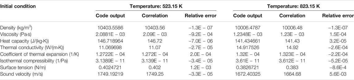
TABLE 1. Accuracy test of LBE thermo-physical properties.
The same verification procedure has been performed for the heat transfer coefficient. Under a wide range of boundary conditions, the relative errors of the heat transfer coefficient calculated by the code and correlation are within 0.5%.
Validation Against NACIE Test
For the preliminary code validation stage, the natural circulation phenomenon, and the accuracy of thermal dynamic properties, heat convective correlations are assessed with the available test data. Two LBE natural circulation tests: 1) one natural circulation startup test (test no. 21 at a power of 22.5 kW) of NACIE facility and 2) natural circulation capability tests of NCCL facility for five different power levels (4.5, 5.8, 7.5, 9.8, and 15 kW), are chosen, which involve various common fluids (LBE, water, and air) to fully demonstrate the accuracy of the modified thermo-hydraulic properties and calculation models. Meanwhile, the primary and secondary loops of these facilities are relatively simple, and thus, it is easier to determine the loop flow resistance considering that the mass flow rate is strongly affected by flow resistance under natural circulation conditions.
Description of NACIE Test Facility
The Natural Circulation Experimental (NACIE) facility was designed at ENEA Brasimone Research Centre to study the natural circulation regime in support of ICE (Integral Circulation Experiment) activities (Tarantino et al., 2010; Tarantino et al., 2011). The schematic of the facility is shown in Figure 1. The NACIE facility loop is rectangular in shape of 7.5 m height and 1 m width consisting of two vertical pipes working as the riser and downcomer and two horizontal branches with an inner diameter of 62.7 mm. A heat source (HS) is installed in the bottom part of the riser, while a heat exchanger (HX) is installed in the upper part of the downcomer.
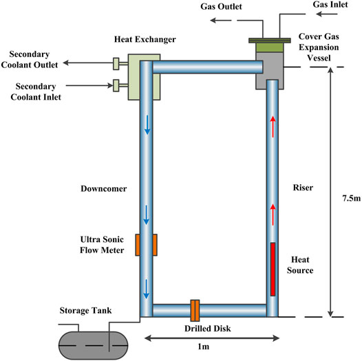
FIGURE 1. NACIE test facility schematic (Tarantino et al., 2011).
Figure 2 shows the cross-sectional view of the heat source. The heat source houses a fuel bundle with two electric rods and two dummy rods with an outer diameter of 8.2 mm. The active length is 850 mm, and the thermal power is 22.5 kW. A grid spacer is installed in the middle of the active length.
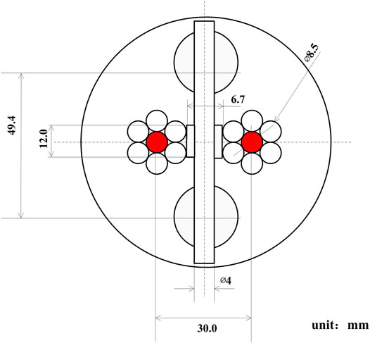
FIGURE 2. NACIE heat source cross section (Tarantino et al., 2011).
As shown in Figure 3, the HX is composed of three coaxial tubes, where LBE flows downward in the inner one and water moves upward through the annular region between the middle and external tubes (Tarantino et al., 2010). The main parameters of the HX are reported in Table 2. The volume between the inner and middle tubes is filled with stainless steel powder to enhance heat transfer (Tarantino et al., 2010). The powder gap thermal conductivity was evaluated as 12.5% of the stainless steel theoretical value, which was demonstrated playing a crucial role in the execution of the test (Coccoluto, et al., 2011).
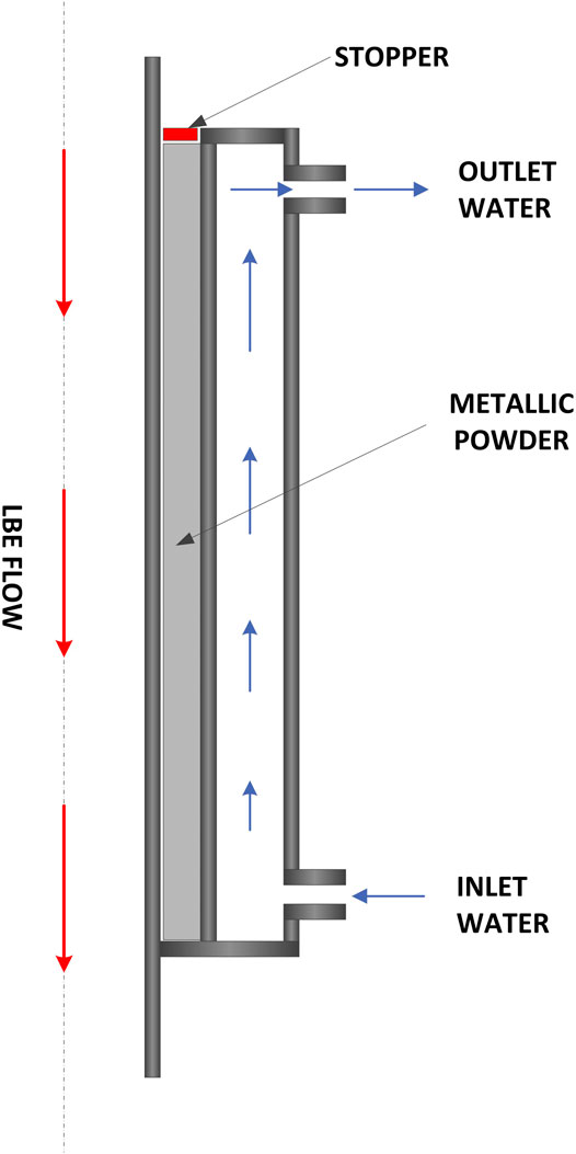
FIGURE 3. View of the NACIE HX (Tarantino et al., 2011).
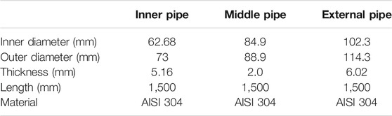
TABLE 2. NACIE HX pipes’ dimension.
Nodalization of NACIE Test Facility
The NACIE facility computational model is shown in Figure 4. The components named “1XX” represent the LBE primary loop, and the number order is consistent with the flowing direction: the pipe component P110 represents the hydrodynamic component of the heat source; P115 represents the riser; P150 represents the internal pipe of the heat exchanger, namely, the primary side of the HX; and P160 represents the downcomer. In the NACIE loop, the pressure of the primary loop is controlled by the cover gas in the expansion vessel. In modeling, the branch component B125 represents the expansion vessel, which is connected to 145 TMDPVOL (filled with air). The argon/LBE free surface is not considered for the reason that only the natural circulation test is simulated and the argon layer has little effect on the natural circulation flow rate. The components named “2XX” represent the secondary side of the HX: 200TMDPVOL specifies the inlet water mass flow rate and temperature, 210P represents the secondary side of the HX, and 220TMDPVOL specifies the outlet pressure.
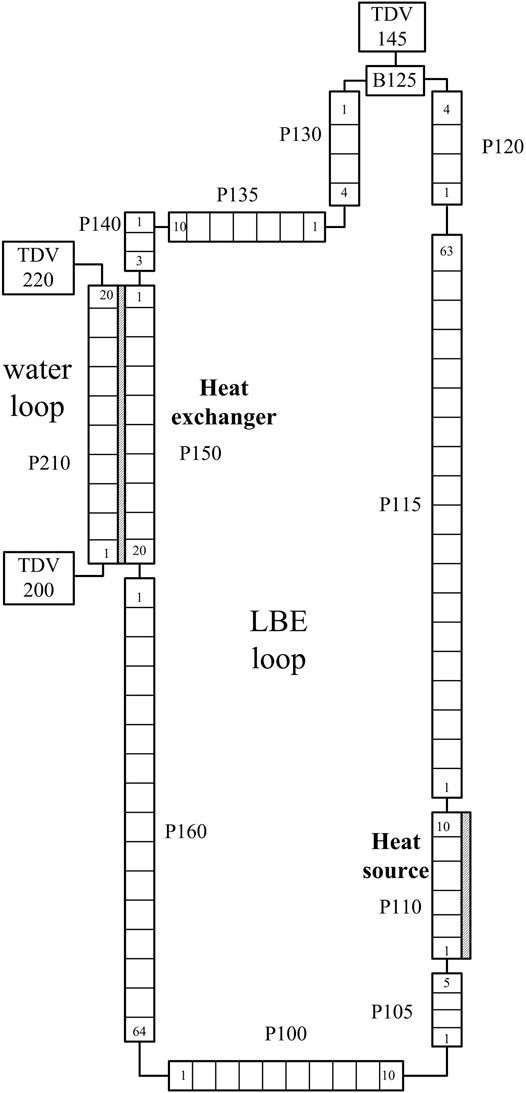
FIGURE 4. NACIE facility nodalization.
The heater power imposed in the HS is simulated by H1110. The heat structure H1150 reproduces heat transfer across the HX walls between the primary tube and the secondary tube. The thermal conductivity of powder gap has been taken from the research of Coccoluto et al. (2011), the value of which is 12.5% of stainless steel. Heat losses between the primary loop and the environment are introduced, assuming an insulation of mineral wool with a thickness of 10 cm. The heat transfer coefficient correlation for the HS and HX adopts the circular pipes’ correlation, as depicted in Eqs 24, Eqs 26.
In RELAP5 simulation, all of the wall roughness is assumed to be 32 μm. The friction coefficient in the spacer grid is provided by the Handbook on Nuclear Power Engineering Thermo-Hydraulics Analysis (Kirillov et al., 2016):
where
An additional flow resistance is added for the elbows of the primary loop, and the resistance is chosen as 0.5. The pressure loss coefficient of sudden expansion from the riser to the expansion vessel is set as 1.0, and the pressure loss coefficient of sudden contraction from the expansion vessel to the upper horizontal pipe is set as 0.5.
Results and Discussion
Test No. 21 performed at the NACIE facility, namely, one natural circulation startup test at a power level of 22.5 kW (Tarantino et al., 2010), has been considered for code assessment. Initial and boundary conditions are as follows: the initial LBE loop is in equilibrium at a temperature of 240°C, primary pressure of 1.0 × 10⁵ Pa, secondary water inlet temperature of 65°C, and secondary pressure of 1.5 × 10⁵ Pa, respectively. The actual startup of natural circulation begins by supplying 22.5 kW power to the electrical heater, and the power ramp time is 1 min (Tarantino et al., 2010), but no detailed description of the feedwater mass flow rate and inlet temperature transient is given. In the simulation, the heating power is assumed to increase linearly during the first 1 min, and the mass flow rate in the water loop increases linearly from zero to 0.55 kg/s.
Figure 5 shows the comparison of temperature variation of inlet and outlet LBE temperatures across the heat source during the natural circulation startup process. At the beginning of the transient, the outlet temperature of the heating source increases to a maximum value quickly. The inlet and outlet LBE temperature trend calculated by the code agrees well with the experimental data during the first 1400 s. There is a noticeable difference between code prediction and test data during the time period from 1400 to 4000 s. The measured inlet and outlet temperatures reached the first peak value, while the code predicted a rather smooth trend. Such discrepancy may attribute to the boundary and initial condition difference in the experiment and simulation. Sensitivity analysis showed that the power and mass flow rate ramp curves have great effect on the temperature distribution. However, after time t > 4000 s, the LBE system starts to attain the steady-state condition. The steady outlet temperature calculated by the code is 363.8°C, while the experimental value is 365.2 ± 1.5°C, with the difference of 1.2°C. The simulated inlet temperature is 336.2°C compared to the experimental one of 337.5 ± 1.5°C, with the difference of 0.8°C. The temperature difference between the simulation and the test is within the thermocouple measurement uncertainty range. The predicted temperature difference between the inlet and the outlet of the HS is 27.6°C, while the one calculated analytically is 28.0°C.
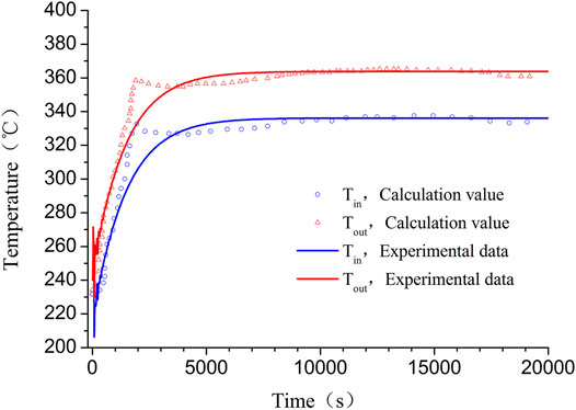
FIGURE 5. Temperature variation of the inlet and outlet across the HS.
In Figure 6, the comparison of the LBE mass flow rate in the primary loop heater source is plotted. The experimental value of LBE mass flow rate is observed to achieve a peak value of 6.8 kg/s at time t = 165 s, and at 2000 s, the mass flow rate goes down rapidly and attains a steady-state value of 5.5 kg/s. The RELAP5 code predicts that the mass flow rate achieves a maximum value of 8.1 kg/s at 50 s and then fluctuates during the first 1,000 s. It should be mentioned that the mass flow rate is not directly measured but derived from the energy balance equation. Actually, during the natural circulation startup process, part of the heating power is used to heat the pipes, which is stored in the structural materials. Therefore, the actual mass flow rate is lower than the derived one. This leads to the mass flow rate discrepancy during 2000 s. The steady LBE natural circulation flow rate computed by the RELAP5 code is 5.46 kg/s, which is very close to the experimental value of 5.5 kg/s.
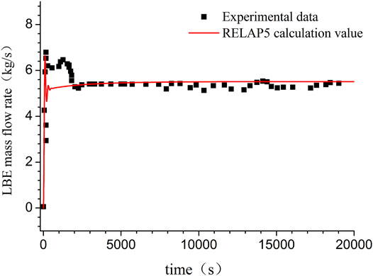
FIGURE 6. Comparison of the mass flow rate of LBE.
The sensitivity analysis of nodalization scheme has been conducted to study its effect on natural circulation results. One of the most important parameters in a natural circulation loop is the mass flow rate, whose value is determined by many different parameters. Therefore, it should be a good parameter to estimate the nodalization effect. The control volume number of component P150 simulating the heat exchanger, N, is set as 10, 15, and 20, respectively. The corresponding calculated natural circulation flow rate is 5.5147, 5.5074, and 5.5036 kg/s, respectively. The calculated mass flow rate decreases only 0.2% when N increases from 10 to 20. Therefore, the final control volume number N of P150 is set as 20.
Validation Against NCCL Test
Description of NCCL Facility
The Natural Circulation Capability Loop (NCCL) facility with its primary and secondary sides is schematically shown in Figure 7. The loop is rectangular in shape of 3.5 m height and 1 m width consisting of a heating section, cooling section, electromagnetic (EM) flowmeter, and EM flowmeter calibration tube (Shi, 2018; Shi et al., 2019). All parts in contact with LBE are made of 316L stainless steel. The diameter of the loop (except for the cooling section) is 0.032 m, and the length of the heating section is 2.1 m (the length of the vertical heating pipe is 1.1 m). The heating section is located at the bottom of the loop, which adopts the indirect heating method by winding the electric heating wire on the tube tightly, and the maximum heating power is 21 kW. The cooling section is located at the upper horizontal branch, which is cooled by air convection. Some fins are arranged on the cooling section to increase the cooling capacity. During the test, the control of power removed by the cooling section is through adjustment of the fin speed. The temperature measurement uncertainty of the NCCL test is within ±1°C, and the mass flow rate uncertainty is within ±1%. The diameter of the horizontal pipe is enlarged to 80 mm, and the vertical pipe diameter is enlarged to 210 mm.
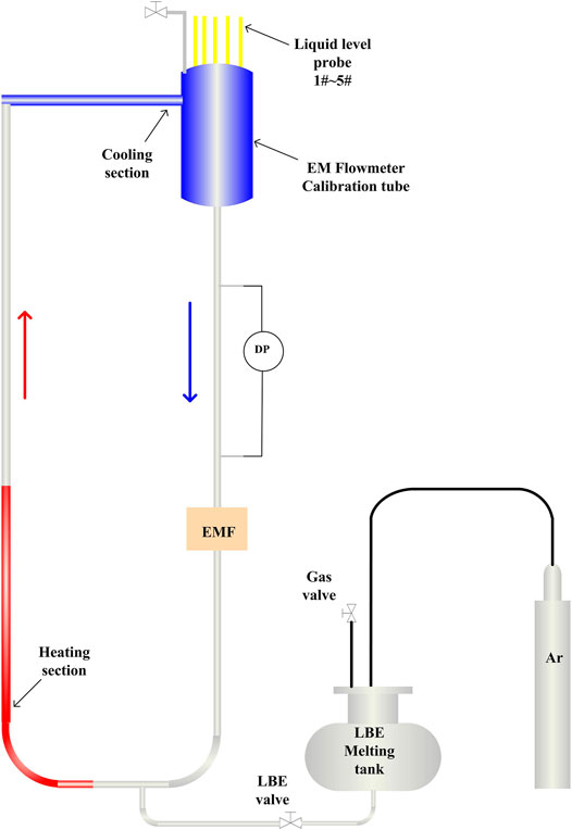
FIGURE 7. Schematic of the NCCL test facility (Shi et al., 2019).
In the NCCL test facility, five groups of natural circulation flow tests are conducted under different input power conditions (p = 4.5, 5.8, 7.5, 9.8, and 15 kW) to study the capability of natural circulation. The tests are conducted in steady-state conditions with a large sum of thermocouples installed in the primary loop to evaluate whether the steady-state condition is achieved. The criterion to achieve the steady-state condition is that the maximum temperature difference of the whole primary loop should be less than 10° C. The maximum LBE temperature difference between the inlet and the outlet of the heating section reaches 73° C, and the corresponding LBE mass flow rate is 0.81 kg/s. The test condition range is rather different from NACIE’s test conditions; therefore, these tests are used to further validate the models employed in the RELAP5 code.
Nodalization of NCCL Facility
The RELAP5 nodalization diagram for the NCCL facility is similar to the nodalization of NACIE facility and is not depicted in this paper. Only the hydrodynamic components in the primary loop are modeled, which include a heating section, riser, cooling section, downcomer, and lower horizontal pipe. In RELAP5 simulation, all of the wall roughness is assumed to be 32 μm. The flow resistance for the elbows of the primary loop is chosen as 0.5. The pressure loss coefficient of sudden expansion from the horizontal pipe to the vertical EM flowmeter calibration tube is set as 1.0, and the pressure loss coefficient of sudden contraction from the EM flowmeter calibration tube to the downcomer is set as 0.5.
The heater power generated by the heater winding has been imposed in the heating section. Heat losses between the primary loop and the external environment have been also introduced in the analyses, assuming an insulation of mineral wool with a thickness of 10 cm. The heat transfer between the primary LBE and air is also modeled, and the appropriate heat transfer coefficient and air temperature are imposed outside the pipe walls. The fluid adopted in the secondary loop is air with the temperature of 30°C. During the simulation, the secondary heat transfer coefficient is adjusted to ensure that the heat removed by fins accommodates the heating power.
Results and Discussion
The experimental value of average LBE temperature difference under five different power levels is 36.0, 42.9, 54.5, 65.7, and 72.4°C, and the corresponding average LBE mass flow rate is 0.60, 0.67, 0.71, 0.75, and 0.83 kg/s, respectively (Shi, 2018).
It should be noted that the heating section is winded by the electric heating wire, which adopts the indirect heating method. Under this condition, the heat loss from the heating wire to the heat section is relatively large and is not negligible. By referring to the experimental data of LBE mass flow rate and inlet and outlet LBE temperatures of the heating section, the actual heating power exerted to the heat section is obtained (see Table 3). In the following RELAP5 calculations, the actual heating power is attached to the heat section.

TABLE 3. Heating power and heat efficiency to the heating section.
Figure 8 depicts the comparison of the LBE mass flow rate between code prediction and experimental data measured under different heating power levels. As can be seen, the code predicts the natural circulation mass flow rate relatively well with respect to the experimental data. The LBE natural circulation mass flow rate increases as the heating power increases, but the slope at higher heating power is relatively smaller than that at lower heating power. This is because at higher heating power, the increase in the mass flow rate will cause the flow resistance increase remarkably.
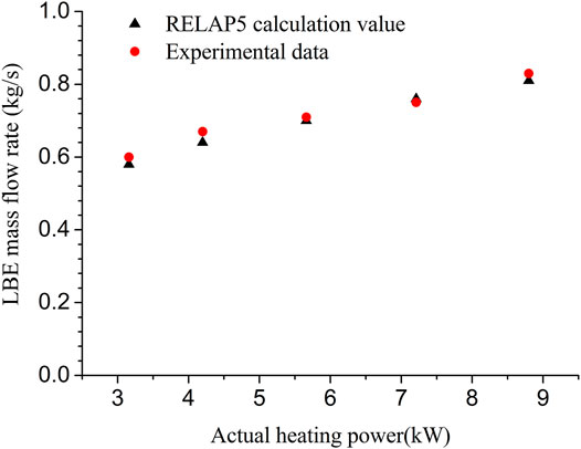
FIGURE 8. Comparison of the LBE mass flow rate under different heating power levels.
The LBE temperature difference trend with different heating power levels from RELAP5 simulation and experimental data is compared in Figure 9. As can be observed, the simulated LBE temperature difference agrees with the experimental data and the maximum discrepancy occurs at the heating power of 7.21 kW with the error of 6.1%. The LBE temperature difference increases as the heating power increases.
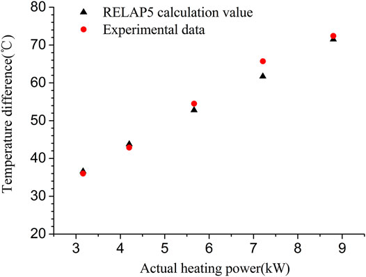
FIGURE 9. Comparison of the LBE temperature difference under different heating power levels.
Similar sensitivity analysis of the nodalization scheme has also been conducted for NCCL test facility modeling. Again, the parameter mass flow rate is chosen to estimate the nodalization effect. The control volume number of the component simulating the heat exchanger, N, is set as 12, 14, and 19, respectively. The corresponding calculated natural circulation flow rate is 0.81109, 0.81113, and 0.81117 kg/s, respectively. The calculated mass flow rate varies within 0.1% when N increases from 12 to 19. Therefore, the final control volume number N is set as 19.
Conclusion
The RELAP5 MOD3.2 code was modified for thermal-hydraulic analysis of LBE-cooled systems. Simulation of tests from the NACIE facility and NCCL facility is conducted for the validation of the modified RELAP5 code. The main results are summarized as follows:
(1) For the natural circulation startup test (test No. 21 at a power of 22.5 kW) of NACIE facility, the simulated trends of LBE temperature and mass flow rate agree well with the experimental data. The steady inlet and outlet LBE temperature difference obtained from the prediction agrees well with the experimental value within a difference of 1°C. The difference between the simulated steady LBE flow rate and the experimental value is within 0.5 kg/s.
(2) For the natural circulation capability tests of NCCL facility under five different power levels, the code predicts the natural circulation mass flow rate relatively well with respect to the experimental data. The simulated LBE temperature difference matches with the experimental data with the maximum error of 6.1%.
(3) The preliminary validation of the modified RELAP5/MOD 3.2 code has been performed in the present work. The modified code gives acceptable results, but more validation work is required for further application for CiADS reactor design and safety analysis.
Data Availability Statement
The original contributions presented in the study are included in the article/Supplementary Material, and further inquiries can be directed to the corresponding author.
Author Contributions
YL is mainly responsible for RELAP5 code modification, code assessment and paper drafting. WL mainly contributes for the LBE thermal property collection, code verification and data processing. XL is mainly responsible for paper review and modification. CG is responsible for code modification method design. ZZ contributes for literature survey and paper review.
Conflict of Interest
The authors declare that the research was conducted in the absence of any commercial or financial relationships that could be construed as a potential conflict of interest.
References
Alemberti, A., Caramello, M., Frignani, M., Grasso, G., Merli, F., Morresi, G., et al. (2020). ALFRED Reactor Coolant System Design. Nucl. Eng. Des. 370, 110884. doi:10.1016/j.nucengdes.2020.110884
Balestra, P., Giannetti, F., Caruso, G., and Alfonsi, A. (2016). New RELAP5-3D lead and LBE Thermophysical Properties Implementation for Safety Analysis of Gen IV Reactors. Sci. Tech. Nucl. Installations 2016, 1–15. Article ID 1687946. doi:10.1155/2016/1687946
Bortot, S., Moisseytsev, A., Sienicki, J. J., and Artioli, C. (2011). Core Design Investigation for a SUPERSTAR Small Modular lead-cooled Fast Reactor Demonstrator. Nucl. Eng. Des. 241, 3021–3031. doi:10.1016/j.nucengdes.2011.04.012
Cheng, X., Cahalan, J. E., and Finck, P. J. (2004). Safety Analysis of an Accelerator-Driven Test Facility. Nucl. Eng. Des. 229, 289–306. doi:10.1016/j.nucengdes.2004.01.003
CIAE CiADS team, (2020). China Initative Acceleratr Driven System–Subcritical LBE Cooled Reactor Project Proposal Report.
Cinotti, L., Smith, C. F., Sienicki, J. J., Aït Abderrahim, H., Benamati, G., Monti, G. Locatelli. S., et al. (2007). The Potential of LFR and ELSY Project Book of Abstracts. ICAPP 2007 Nice, France (Paper 7585.
Coccoluto, G., Gaggini, P., Labanti, V., Tarantino, M., Ambrosini, W., Forgione, N., et al. (2011). Heavy Liquid Metal Natural Circulation in a One-Dimensional Loop. Nucl. Eng. Des. 241, 1301–1309. doi:10.1016/j.nucengdes.2010.06.048
Gu, Z., Wang, G., Wang, Z., Song, Y., and Zhao, Z. (2016). Safety Analyses of 10 MW Th Forced Circulation LBE-Cooled Fast Reactor during Unprotected Transients. Ann. Nucl. Energ. 88, 112–117. doi:10.1016/j.anucene.2015.11.004
Jaeger, W. (2017). Heat Transfer to Liquid Metals with Empirical Models for Turbulent Forced Convection in Various Geometries. Nucl. Eng. Des. 319, 12–27. doi:10.1016/j.nucengdes.2017.04.028
Jeong, S. H. (2006). Development of an Integral Test Loop, HELIOS and Investigation of Natural Circulation Ability for PEACER, In Nuclear Engineering Department. Seoul: Seoul National University.
Kirillov, П. Л., Bobukov, B. Π., Zhukov, A. B., and Yuriyev, Ю. C. (2016). Handbook on Nuclear Power Engineering Thermo-Hydraulics Analysis. Chinese Atomic Energy Press (ISBN 978-7-5022-7440-5.
Kööp, K., Jeltsov, M., Grishchenko, D., and Kudinov, P. (2017). Pre-test Analysis for Identification of Natural Circulation Instabilities in TALL-3D Facility. Nucl. Eng. Des. 314, 110–120. doi:10.1016/j.nucengdes.2017.01.011
Kumari, I., and Khanna, A. (2017). Preliminary Validation of RELAP5/Mod4.0 Code for LBE Cooled NACIE Facility. Nucl. Eng. Des. 314, 217–226. doi:10.1016/j.nucengdes.2017.02.004
Lim, J.-Y., and Kim, M.-H. (2007). A New LFR Design Concept for Effective TRU Transmutation. Prog. Nucl. Energ. 49 (3), 230–245. doi:10.1016/j.pnucene.2006.12.004
Ma, W., Karbojian, A., and Sehgal, B. R. (2007). Experimental Study on Natural Circulation and its Stability in a Heavy Liquid Metal Loop. Nucl. Eng. Des. 237, 1838–1847. doi:10.1016/j.nucengdes.2007.02.023
Martelli, D., Forgione, N., Barone, G., and di Piazza, I. (2017). Coupled Simulations of the NACIE Facility Using RELAP5 and ANSYS FLUENT Codes. Ann. Nucl. Energ. 101, 408–418. doi:10.1016/j.anucene.2016.11.041
Handbook on Lead-Bismuth Eutectic (2007). in Alloy and Lead Properties, Materials Compatibility, Thermal Hydraulics and Technologies. Editor N. OECD (Nuclear Energy Agency, Organisation for Economic Co-operation and Development), 7268.
Narcisi, V., Lorusso, P., Giannetti, F., Alfonsi, A., and Caruso, G. (2019). Uncertainty Quantification Method for RELAP5-3D Using RAVEN and Application on NACIE Experiments. Ann. Nucl. Energ. 127, 419–432. doi:10.1016/j.anucene.2018.12.034
RELAP5/MOD3 code manual (1998). Volume I: Code Structure, System Models and Solution Methods, NUREG/CT- 5535. US: Idaho National Laboratory.
Rubbia, C. (1996). Status of the Energy Amplifier Concept, In Proceeding of the 2nd International Conference on Accelerator-Driven Transmutation Technologies and Applications. Sweden: Kalmar, 3–7.
Seban, R. A., and Shimazaki, T. T. (1950). ASME.Heat Transfer to a Fluid Flowing Turbulently in a Smooth Pipe with walls at Constant Temperature Paper No. 50-A-128
Shi, L. (2018). Research of Flow, Heat Transfer and Natural Circulation Characteristics of Lead-Bismuth Eutectic. PhD Thesis.
Shi, L., Su, G. H., Zhu, F., Bing, T., Hou, Y., Wei, S., et al. (2019). Experimental Study on the Natural Circulation Capability and Heat Transfer Characteristic of Liquid lead Bismuth Eutectic. Prog. Nucl. Energ. 115, 99–106. doi:10.1016/j.pnucene.2019.03.003
Smith, C. F., Halsey, W. G., Brown, N. W., Sienicki, J. J., Moisseytsev, A., and Wade, D. C. (2008). SSTAR: The US lead-cooled Fast Reactor (LFR). J. Nucl. Mater. 376, 255–259. doi:10.1016/j.jnucmat.2008.02.049
Tarantino, M., Agostini, P., Benamati, G., Coccoluto, G., Gaggini, P., Labanti, V., et al. (2011). Integral Circulation Experiment: Thermal-hydraulic Simulator of a Heavy Liquid Metal Reactor. J. Nucl. Mater. 415, 433–448. doi:10.1016/j.jnucmat.2011.04.033
Tarantino, M., Bernardi, D., Coccoluto, G., Gaggini, P., Labanti, V., and Forgione, N. (2010). Natural and Gas Enhanced Circulation Tests in the NACIE Heavy Liquid Metal Loop, In Proceedings of the 18th International Conference on Nuclear Engineering ICONE18. Xi’an, China. doi:10.1115/icone18-29968
Zrodnikov, A., Toshinsky, G. I., Komlev, O. G., Dragunov, Y. G., Stepanov, V. S., Klimov, N. N., et al. (2006). Nuclear Power Development in Market Conditions with Use of Multi-Purpose Modular Fast Reactors SVBR-75/100. Nucl. Eng. Des. 236, 1940–1502. doi:10.1016/j.nucengdes.2006.04.005
Keywords: RELAP5 code, lead–bismuth eutectic, LBE-cooled fast reactor, thermo-physical properties, natural circulation
Citation: Lv Y, Liu X, Li W, Guo C and Zhou Z (2021) Assessment of Modified RELAP5 MOD3.2 Against LBE Natural Circulation Test Loops. Front. Energy Res. 9:674353. doi: 10.3389/fenrg.2021.674353
Received: 01 March 2021; Accepted: 19 May 2021;
Published: 11 June 2021.
Edited by:
Jun Wang, University of Wisconsin-Madison, United StatesReviewed by:
Vincenzo Narcisi, Sapienza University of Rome, ItalyHongli Chen, University of Science and Technology of China, China
Copyright © 2021 Lv, Liu, Li, Guo and Zhou. This is an open-access article distributed under the terms of the Creative Commons Attribution License (CC BY). The use, distribution or reproduction in other forums is permitted, provided the original author(s) and the copyright owner(s) are credited and that the original publication in this journal is cited, in accordance with accepted academic practice. No use, distribution or reproduction is permitted which does not comply with these terms.
*Correspondence: Xingmin Liu, MTM2NzExMDA0NzhAMTM5LmNvbQ==