 Kenneth E. Okedu
 Maamar Al Tobi
 Saleh Al Araimi
- 1Department of Electrical and Electronic Engineering, Nisantasi University, Istanbul, Turkey
- 2Department of Electrical and Electronic Engineering, Kitami Institute of Technology, Kitami, Japan
- 3Department of Electrical and Communication Engineering, National University of Science and Technology, Muscat, Oman
- 4Department of Mechanical Engineering, National University of Science and Technology, Muscat, Oman
This study investigates the transient performance of two variable speed wind turbines (VSWTs), namely doubly fed induction generator (DFIG) and the permanent magnet synchronous generator (PMSG), that are widely employed in wind energy conversion, considering their machine parameters. The machine parameters of both wind turbines were changed considering different scenarios, while keeping other parameters constant, to study the behavior of the wind generators. This study was carried out using the same operating conditions of rated wind speed, based on the characteristics of both wind turbine technologies. The wind turbines were subjected to a severe three phase to ground bolted fault to test the robustness of their controllers during grid fault conditions. Efforts were made to carry out an extensive comparative study to investigate the machine parameters that have more influence on the stability of the different wind turbines considered in this study. Simulations were carried out using power system computer-aided design and electromagnetic transient including DC (PSCAD/EMTDC). Effective machine parameter selection could help solve fault ride-through (FRT) problems cost-effectively for both VSWTs, without considering the external circuitry of and changing the original architecture of the wind turbines.
Introduction
Variable speed wind turbines (VSWTs) are the new norms for the installation of wind farms. These types of wind turbines have high efficiency in capturing energy, with effective voltage control (Okedu, 2019a). The doubly fed induction generator (DFIG) and permanent magnet synchronous generator (PMSG) with back-to-back power converter-type technologies have become the two wind generator alternatives, commonly employed as VSWTs. The former has a gearbox, and only 20–30% of the generator rating is required for its operating speed range of 0.7–1.3 per unit (p.u.). The latter has a drawback of high cost due to its full-rated power converters.
In the DFIG wind turbine structure, the back-to-back power converter lies between the rotor or machine side and the stator or grid side. Based on the available wind speeds, this type of wind turbine can operate at a wide range for better wind energy capture (Godoy Simoes and Farret, 2004; Bozhko et al., 2008). In the DFIG wind turbine, rebuilding of the terminal voltage after grid disturbance is much easier due to the pitch and dynamic slip control strategy (Okedu and Barghash, 2021a,b). Moreover, the control of active and reactive power through the decoupling principles is much easier in this class of wind turbine. The power converters of the DFIG wind turbine go into standby mode (Haberberger and Fuchs, 2004) at lower voltages (El-Sattar et al., 2008; Okedu et al., 2012; Okedu and Barghash, 2021a,b); however, during grid fault, above the threshold voltages, there is fast synchronization of this type of wind generator to the power grid (Santos and Le, 2007).
On the other hand, the alternative to the DFIG wind turbine in wind energy conversion is the PMSG wind turbine technology. The PMSG wind turbine has a full-rated back-to-back power converter tied to the power grid. Consequently, there is maximum flexibility in this type of wind generator compared with the DFIG topology (Okedu, 2011; Okedu and Barghash, 2021c). Thus, real and reactive power control is more effective when using the PMSG wind turbine. However, high initial cost is the major drawback of this class of wind turbine system (Baran and Andrzej, 2020).
Based on the literature, there are many fault ride-through (FRT) control strategies in the enhancement of DFIG and PMSG wind turbines. Fault current limiters (Okedu et al., 2011a,b; Okedu, 2016), crowbar switch and DC chopper circuitry (Takahashi et al., 2006; Okedu et al., 2010a), and sliding mode controls (Okedu et al., 2010b; Bekakra and Attous, 2011) are some of the FRT schemes already reported in the literature for the improvement of the transient stability of either or both wind turbines. The assessment of DFIG using various control methods was carried out in different studies (Ali et al., 2010; Lamchich and Lachguer, 2012; Suthar, 2014), with emphasis on the use of maximum power point tracking (MPPT) pitch angle controller considering different algorithms (Noubrik et al., 2011), while peak current limitation and MPPT were employed by Nasiri and Mohammadi (Nasiri and Mohammadi, 2017) and Gencer (2018), respectively. In a study by Moghimyan et al. (2020), a series fault current limiter was employed with metal oxide varistor to improve the low-voltage ride-through (LVRT) of DFIG-based wind farms. The application of a multistep bridge-type fault current limiter for the PMSG wind turbine was reported by Firouzi et al. (2020a) for the improved performance of the wind turbine FRT. A neuro-fuzzy logic-controlled parallel resonance-type fault current limiter scheme was employed by Islam et al. (2020) to enhance the FRT capability of a wind farm composed of DFIG wind turbines, while entire power systems using fuzzy logic-controlled capacitive bridge-type fault current limiter scheme was investigated by Sadi et al. (2021). A further approach of using dynamic multicell fault current limiter was reported by Shafiee et al. (2020) to improve the FRT performance of the wind farms based on DFIG control, while a sliding mode controller based on the bridge-type fault current limiter was used for the DFIG FRT-improved performance (Firouzi et al., 2020b).
The machine parameters help in understanding the performance of the wind generators. These parameters are additional quantities that influence the behavior of the wind turbines. However, compared with the input variables, the machine parameters are held constant, or change slowly during the operation of the wind turbines (Nykamp, 2020). The machine parameters present some unique functions that should be observed in order to improve the maximum power generation output and efficiency of the wind turbines (Abolude and Zhou, 2018). The evaluation of the mechanical parameters affecting wind turbine power generation was carried out (Construction review, 2019); however, the parameters investigated were limited to the swept area, air density, wind speed, and power coefficient of the wind turbine. According to Rose and Hiskens (Rose and Hiskens, 2008), the wind turbine parameters were estimated and these effects were used to quantify their dynamic behavior. The study was limited to the estimation of certain parameters, without extensive study of their effects during transient conditions. According to Balijepalli et al. (2018), an optimized parameter design for the blades of wind turbine considering Schmitz theories and aerodynamics forces was reported.
In light of the earlier discussion, this study presents the effects of the electrical parameters of wind turbines during grid fault. There are limited reports on the effects of electrical parameters considering the DFIG and PMSG VSWTs in the literature. Therefore, this study tends to bridge this research gap. The characteristics, modeling, and control strategies of DFIG and PMSG wind turbines were presented. The extensive investigation of the effects of various parameters was considered, by varying some machine parameters while keeping the other parameters constant. In the DFIG analysis, nine scenarios were considered, while in the PMSG analysis, ten scenarios were considered. The machine parameters considered for the DFIG wind turbine are magnetizing inductance, stator leakage inductance, wound rotor leakage inductance, stator resistance, wound rotor resistance, and angular moment of inertia. The machine parameters considered for the PMSG wind turbine are stator winding resistance, stator leakage reactance, D: unsaturated reactance, Q: unsaturated reactance, D: damper winding resistance, D: damper winding reactance, Q: damper winding reactance, Q: damper winding resistance, and magnetic strength. The same wind turbine capacity and the same fault condition of operation were considered for both wind turbine technologies, and the turbines were operated at their rated speed based on their MPPT wind turbine characteristics. The simulation analysis was carried out using a power system computer-aided design and electromagnetic transient including DC (PSCAD/EMTDC) (PSCAD/EMTDC Manual, 2016).
Turbine Characteristics and Model of DFIG Wind Turbine
The characteristics of the DFIG wind turbine used in this study are shown in Figure 1, with the range of the rotor speed between 0.7 and 1.3 p.u. The DFIG equivalent circuit (Okedu, 2019b, 2020) tied to the power grid is shown in Figure 2, with the back-to-back power converters linking the point of common coupling (PCC).
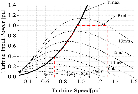
Figure 1. The DFIG wind turbine characteristics.
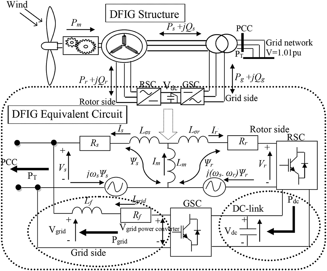
Figure 2. DFIG grid connection scheme.
As shown in Figure 2, the total power is (PT = Ps+Pg), and it is delivered based on the available wind speed through the rotor and stator circuits of the wind turbine to the PCC, for ωr > ωs (i.e., rotor speed is greater than synchronous speed). The stator active power Ps is delivered to the PCC through the stator circuitry (ωr < ωs), while the absorption of the active power Pr from the PCC is done via the power converter (Zubia et al., 2012). In the d–q orientation stator frame synchronous axis, the application of vector control would lead to the wind generator model on the fifth order d–q representation (Kong et al., 2014). Therefore, the stator, rotor, and the d–q components, considering the equivalent circuit for the DFIG wind turbine as shown in Figure 2, are
From Equations (1–3), the direct and quadrature axis stator reference frame components are given by d and q, respectively, while s, r, and m are the stator, rotor, and mutual quantities and components V, I, and Ψ represent voltage, current, and flux vector quantities. L and R are the inductance and resistance. ωslip = (ωs − ωr), where ωr and ωs are the electrical rotor and synchronous speeds, respectively. Lr and Ls are the total inductance in rotor and stator circuits and are given by Ls = Lm + Lσs and Lr = Lm + Lσr.
The DC-link dynamics with respect to the DC power is given as
In Equation (4), Cdc, Vdc, and Pdc are the DC-link capacitor, DC-link voltage, and DC-link power. The DFIG rotor side converter (RSC) control scheme is shown in Figure 3, where the q and d axis rotor currents iqr and idr regulate the active and reactive power (Ps, Qs), of the stator, respectively. The stator power of the wind generator is obtained by the MPPT scheme of the wind turbine system. The grid side converter (GSC) of the wind generator, as shown in Figure 4, utilizes the AC grid reference frame to regulate the DC-link voltage and flow of reactive power exchange (i.e., absorption and dissipation) in the PCC according to the power flow direction of the rotor circuit of the wind turbine. The dq-to-abc and abc-to-dq voltage angles transformation based on the AC voltage synchronization is achieved with the help of phase lock loop (PLL) control strategy.
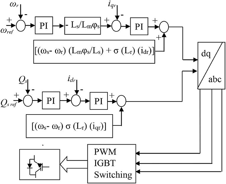
Figure 3. The rotor side converter control circuit of the DFIG.
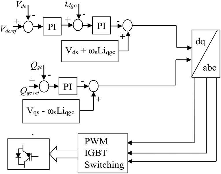
Figure 4. The grid side converter control circuit of the DFIG.
Turbine Characteristics and Model of PMSG Wind Turbine
Figure 5 shows the PMSG wind generator characteristics, for the output power and rotational speed for different wind speeds, based on the maximum obtainable power output of 1.0 p.u. at 1.0 p.u. rotational speed. The reference power Pref of the wind turbine is related to the rated power.
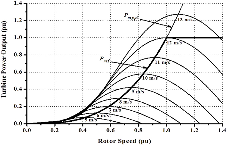
Figure 5. The PMSG wind turbine maximum power characteristics.
The rotating frame based on d–q reference for the model dynamics in the PMSG wind turbine is expressed as Li et al. (2010):
Considering Equations (5) and (6),
where Vsd and Vsq are the voltages of the stator circuit, Rs is the winding resistance of the stator, Isd and Isq are the currents in the stator d and q reference frames, ωe is the rotational speed of the wind generator, Ψsd and Ψsq are the flux linkages of the stator circuit, Lsd and Lsq are the stator wind leakage inductances, Lmd and Lmq are the magnetizing inductances, and Ψm is the linkage flux of the permanent magnet of the machine. Substituting Equations (7) and (8) into (5) and (6), the differential equations for the PMSG wind turbine are
The active and reactive powers of the PMSG are given as
The electrical torque with respect to number of pole pairs is given as
Figure 6 shows the controller of the machine side converter (MSC) and the GSC of the PMSG wind turbine. The MSC regulates both active and reactive power variables of the wind generator. The angle position rotor (θr) helps in achieving the abc to dq transformation by the rotor speed of the wind generator. The d-axis current (Isd) controls the active power (Ps) of the wind generator, while the q-axis current (Isq) regulates the reactive power (Qs) of the wind generator, respectively. The MPPT technique for the characteristic of the wind turbine, as shown in Figure 5, is employed in the reference active power (Pref). Usually, the reference reactive power (Qs*) is fixed at 0 to obtain the effective operation of power factor 1. The three-phase reference voltages (Vsa*, Vsb*, and Vsc*) are generated for the PWM switching, through the outputs of the current controller, based on the voltage references Vsd* and Vsq*. The GSC control of the wind generator is also shown in Figure 6 and is regulated by considering the d–q rotating reference frame, based on the voltage of the grid as same as the speed of rotation. The Park transformation is used in converting (Iga, Igb, and Igc) and (Vga, Vgb, and Vgc) three-phase voltage and current of the grid into their rotating reference d–q frame. The extraction of the phase angle (θg) of the grid side is done by considering the PLL.
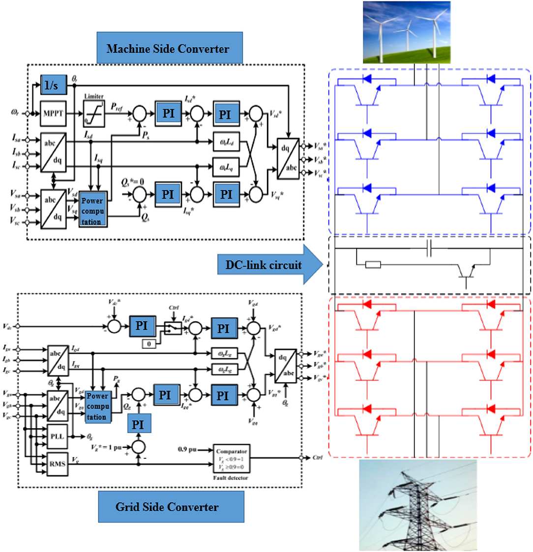
Figure 6. Control strategy of the PMSG wind turbine.
Evaluation of the System Performance
DFIG Wind Turbine Machine Parameters Evaluation
Simulation was carried out considering the nine scenarios summarized in Table 1, for the DFIG machine parameters in p.u. values. This type is a severe three-phase fault of 100 ms happening at 0.1 s, with the circuit breakers operation sequence opening and reclosing at 0.2 and 1.0 s, respectively, on the faulted line at the terminals of the DFIG wind turbine. The system performance was evaluated using PSCAD/EMTDC environment. Some of the simulation results for the cases considered are shown in Figures 7–15B, based on the design machine parameters obtained from the manufacturers of the wind turbine.
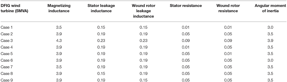
Table 1. DFIG machine parameters (Hitachi Heavy Equipment Construction, 2012).
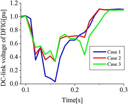
Figure 7. DC-link voltage of DFIG (cases 1–3).
In the first part of the analysis, cases 1–3 were considered. In case 1, the values of the machine parameters were the original values used by the DFIG wind generator. The machine parameters were changed for cases 2 and 3, considering a uniform increment for all the parameters. As shown in Figure 7, when the machine parameters were too high or too low, the DC-link voltage of the DFIG wind turbine response was not improved compared with case 2. In cases 1 and 3, the DC-link voltage variable had more voltage dip with less recovery time. Since the DC-link voltage is related to the response of the active power of the wind generator, the same pattern of response could be observed in Figure 8 for the active power of the DFIG wind generator, where case 2 gave an improved performance. As shown in Figure 9, more reactive power was dissipated by increasing the machine parameters of the DFIG wind generator; consequently, an improved terminal voltage response was observed and is shown in Figure 10. However, in case 3, there was more overshoot of the terminal voltage variable compared with case 2. Figure 11 shows that lower machine parameters of the DFIG wind generator would result in less oscillation of the rotor speed variable during transient state; however, it could be trade off compared with the improved performance obtained for the other variables of the wind generator.
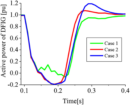
Figure 8. Active power of DFIG (cases 1–3).
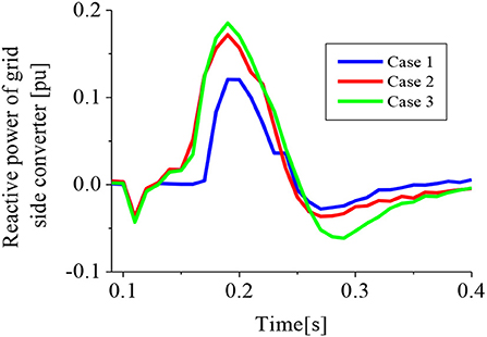
Figure 9. Reactive power of GSC of DFIG (cases 1–3).
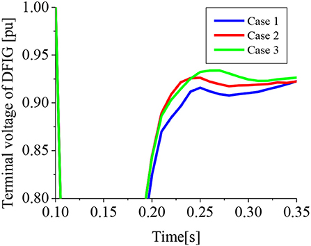
Figure 10. Terminal voltage of DFIG (cases 1–3).
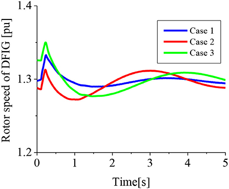
Figure 11. Rotor speed of DFIG (cases 1–3).
A further analysis was carried out considering the best values for case 2, where an improved performance of the DFIG wind turbine variables was obtained during transient state. The machine parameters were changed and kept constant for cases 4–9, as summarized in Table 1, to understand the behavior of the DFIG variables during grid fault. Some of the simulation results for this analysis are given in Figures 12–15B.
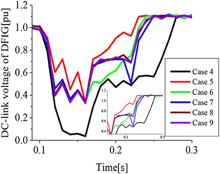
Figure 12. DC-link voltage of DFIG (cases 4–9).
In case 4, the stator resistance of the DFIG wind turbine was changed, while keeping the other machine parameters constant based on the best obtained values in case 2. In case 5, the wound rotor resistance was changed, while in case 6, the angular moment of inertia was changed. In cases 7 and 8, the magnetizing inductance and the stator leakage inductance were changed, respectively. In case 9, the wound rotor leakage inductance was changed. It could be observed that varying the stator resistance has a huge effect on the DC-link voltage and active power of the DFIG as shown in Figures 12, 13. In addition, cases 5 and 6 have significant effect on the DC-link voltage of the wind generator. However, cases 7–9 have no effect on the performance of the DFIG DC-link voltage during transient state. As shown in Figure 14, there is much effect on the reactive power of the DFIG wind turbine, considering cases 4 and 6. However, more reactive power was dissipated for case 5, while cases 7–9 have no significant effect on the reactive power of the wind turbine. Cases 4 and 6 have more effect on the terminal voltage of the DFIG wind turbine, while cases 5–9 have no significant effect on the terminal voltage variable of the wind turbine. Case 5 gave the best performance of the rotor speed of the DFIG wind turbine compared with the other cases. It can be seen from the above results that the variation of the stator resistance in case 4 has much influence on the transient stability of the DFIG during grid fault.
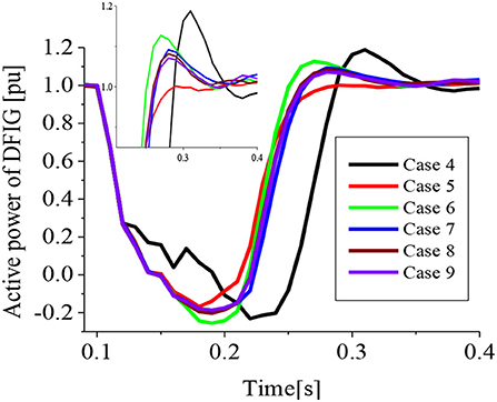
Figure 13. Active power of DFIG (cases 4–9).
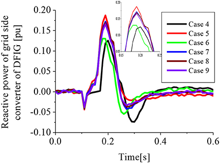
Figure 14. Reactive power of GSC of DFIG (cases 4–9).
PMSG Wind Turbine Machine Parameters Evaluation
Simulation was carried out considering ten scenarios, as summarized in Table 2, for the PMSG machine parameters in p.u. values. The same fault conditions and scenarios used for the DFIG wind turbine in section (A) were considered for the PMSG wind turbine analysis in this section. This type is a severe three-phase fault of 100 ms happening at 10.1 s, with the circuit breakers operation sequence opening and reclosing at 10.2 and 11.0 s, respectively, on the faulted line at the terminals of the PMSG wind turbine. In the first part of the analysis, cases 1–3 were considered. The values of the machine parameters in case 1 were the original values used by the PMSG wind generator. The machine parameters were changed for cases 2 and 3, considering a uniform increment for all the parameters. Some of the simulation results are shown in Figures 15C–18B, based on the design machine parameters obtained from the manufacturers of the wind turbine.
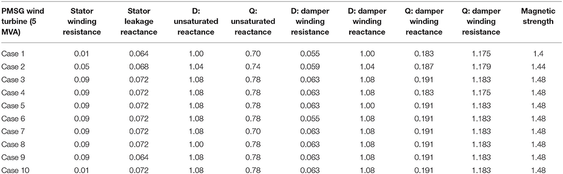
Table 2. PMSG machine parameters (Hitachi Heavy Equipment Construction, 2012).
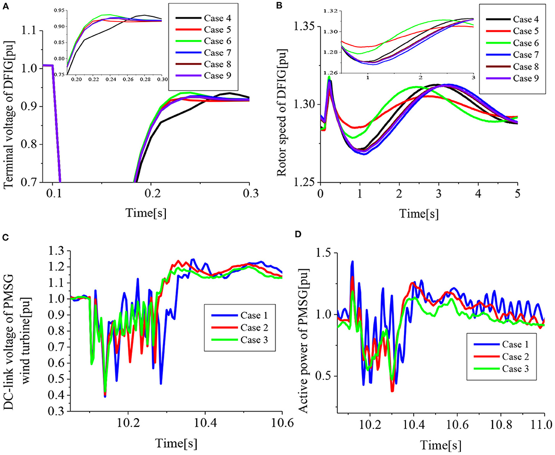
Figure 15. (A) Terminal voltage of DFIG (cases 4–9). (B) Rotor speed of DFIG (cases 4-9). (C) DC-link voltage of PMSG (cases 1–3). (D) Active power of PMSG (cases 1–3).
As shown in Figures 15C,D, case 3 gave the best performance of the DC-link and active power of the PMSG wind turbine during transient state, with faster recovery, short settling time, and less oscillations. The same behavior could be observed for the reactive power of the GSC, terminal voltage, and rotor speed of the PMSG wind turbine as shown in Figure 16, respectively. From the results, too low values of the machine parameters of the PMSG wind turbine led to poor performance compared with the use of higher values of the PMSG machine parameters. Thus, the best values of case 3 were used for further analysis of the PMSG wind turbine machine parameters in cases 4–10 by varying the parameters. In case 4, the Q: damper winding reactance was changed and other machine parameters were kept constant, while in case 5, the D: damper winding reactance was changed. In case 6, the D: damper winding resistance was changed, while in case 7, Q: unsaturated reactance was changed. The D: unsaturated reactance was changed in case 8, while in case 9, the stator leakage reactance was changed. Case 10 considered the variation of the stator winding resistance machine parameters of the PMSG wind turbine. A further analysis of the effect of the machine parameters was considered by varying these parameters for cases 4–10 as summarized in Table 2. Some of the simulation results are shown in Figures 17, 18.
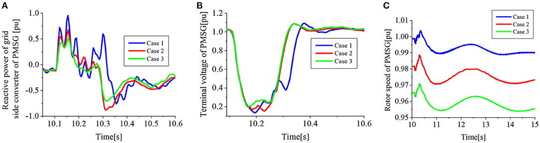
Figure 16. (A) Reactive power of GSC of PMSG (cases 1–3). (B) Terminal voltage of PMSG (cases 1–3). (C) Rotor speed of PMSG (cases 1–3).
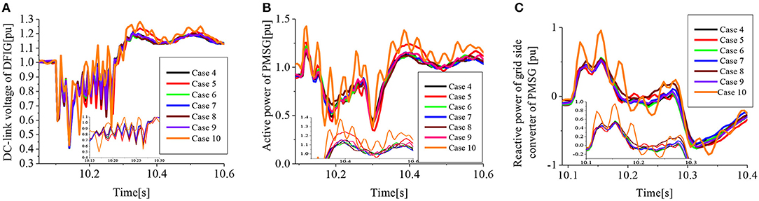
Figure 17. (A) DC-link voltage of PMSG (cases 4–10). (B) Active power of PMSG (cases 4–10). (C) Reactive power of GSC of PMSG (cases 4-10).
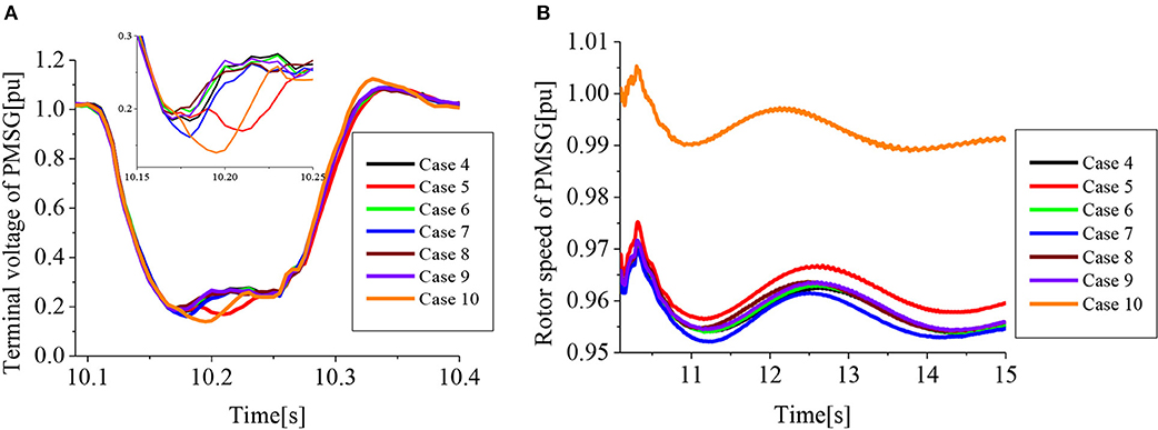
Figure 18. (A) Terminal voltage of PMSG (cases 4–10). (B) Rotor speed of PMSG (cases 4–10).
Cases 8 and 10 have a huge influence on the DC-link voltage and active power of the PMSG wind turbine as shown in Figures 17A,B, while cases 4–7 and 9 have minimal or no influence on the PMSG variables. As shown in Figure 17C, the reactive power variable of the PMSG is much affected in case 10, compared with the other cases, while as shown in Figure 18A, cases 5 and 10 have minimal influence on the terminal voltage variable of the PMSG, compared with the other cases with no significant effect. Figure 18B shows that case 10 has a huge influence on the rotor speed of the PMSG wind turbine, by increasing its value compared with case 5, with less effect and the other cases with insignificant effect on the variable of the PMSG. From the results, it could be observed that the variation in the stator winding resistance of the PMSG wind turbine machine parameter in case 10 has great significance in its performance during grid fault.
Conclusion
The performance of two VSWTs, namely DFIG and PMSG, was investigated during severe grid fault, considering their machine parameters. The commercial values of the machine parameters (case 1) used in this study for both wind turbines, were obtained from Hitachi Laboratory, Hokkaido, Japan. When the machine parameters are way higher or lower than the reference commercial values, the performance of the DFIG wind turbine during transient state, was greatly affected. The moderate values of the machine parameters of the DFIG wind turbine are better for improved performance during grid fault. In addition, the stator resistance parameter has much influence on the variables of the DFIG wind turbines during transient state. Too low machine parameters affect the PMSG wind turbines during transient state. The stator winding resistance of the PMSG affects greatly the performance of the PMSG variables during transient state.
Therefore, for both wind turbine technologies, the stator winding resistance machine parameter has a significant effect on the wind turbine compared with the other parameters. Consequently, a careful selection of the stator winding resistance based on the design of the wind turbine could help improve the FRT challenges posed by these wind turbines during transient state. This may be a cost-effective way without considering external circuitry when compared with most existing FRT solutions for the wind turbines.
Data Availability Statement
The original contributions presented in the study are included in the article/supplementary material, further inquiries can be directed to the corresponding author/s.
Author Contributions
KO did the conceptualization, literature review, simulation results, analysis, and writing of the paper. SA did part of the literature review and sponsorship of the paper. MA did part of the literature review and sponsorship of the paper. All authors contributed to the article and approved the submitted version.
Funding
The work is sponsored by the National University of Science and Technology, Muscat, Oman and the Nisantasi University, Istanbul, Turkey.
Conflict of Interest
The authors declare that the research was conducted in the absence of any commercial or financial relationships that could be construed as a potential conflict of interest.
References
Abolude, T., and Zhou, W. (2018). Assessment and performance evaluation of a wind turbine power output. Energies 11, 1–15. doi: 10.3390/en11081992
Ali, D. M., Jemli, K., Jemli, M., and Gossa, M. (2010). Doubly fed induction generator, with crowbar system under micro-interruptions fault. Int. J. Electr. Eng. Inform. 2, 216–231. Available online at: https://revue.cder.dz/index.php/rer/article/view/231
Balijepalli, R., Chandramohan, V. P., and Kirankumar, K. (2018). Optimized design and performance parameters for wind turbine blades of a solar updraft Tower (SUT) plant using theories of schmitz and aerodynamics forces. Sust. Energy Technol. Assess. 30, 192–200. doi: 10.1016/j.seta.2018.10.001
Baran, J., and Andrzej, J. (2020). An MPPT control of a PMSG-based WECS with disturbance compensation and wind speed estimation. Energies 13, 1–20. doi: 10.3390/en13236344
Bekakra, Y., and Attous, D. B. (2011). Sliding mode controls of active and reactive power of a DFIG with MPPT for variable speed wind energy conversion. Austr. J. Basic Appl. Sci. 5, 2274–2286.
Bozhko, S., Asher, G., Li, R., Jon, C., and Yao, L. (2008). Large offshore DFIG-based wind farm with line-commutated HVDC connection to the main grid: engineering studies. IEEE Trans. Energy Conversion 23:914155. doi: 10.1109/TEC.2007.914155
Construction review. (2019). Major parameters that influence Wind Turbines Power Output. Available online at: https://constructionreviewonline.com/renewables/major-parameters-that-influence-wind-turbines-power-output/ (accessed March 16, 2021).
El-Sattar, A., Saad, N. H., and Shams El-Dein, M. Z. (2008). Dynamic response of doubly fed induction generator variable speed wind turbine under fault. Electric Power System Res. 78, 1240–1246. doi: 10.1016/j.epsr.2007.10.005
Firouzi, M., Nasiri, M., Benbouzid, M., and Gharehpetian, G. B. (2020a). Application of multi-step bridge-type fault current limiter for fault ride-through capability enhancement of permanent magnet synchronous generator-based wind turbines. Int. Trans. Electr. Energy 30:e12611. doi: 10.1002/2050-7038.12611
Firouzi, M., Nasiri, M., Mobayen, S., and Gharehpetian, G. B. (2020b). Sliding mode controller-based bfcl for fault ride-through performance enhancement of DFIG-based wind turbines. Complexity 2020, 1–12. doi: 10.1155/2020/1259539
Gencer, A. (2018). Analysis and control of fault ride through capability improvement PMSG based on WECS using active crowbar system during different fault conditions. Elektron. Elektrotech 24, 64–69. doi: 10.5755/j01.eie.24.2.20637
Godoy Simoes, M., and Farret, F. A. (2004). Renewable Energy Systems: Design and Analysis With Induction Generators. Florida: CRC Press, LLC.
Haberberger, M., and Fuchs, F. W. (2004). “Novel protection strategy for current interruptions in IGBT current source inverters,” in Proceedings EPE-PEMC (Oslo).
Hitachi Heavy Equipment Construction. (2012). Wind Turbines for Power and Energy Laboratory. Hokkaido: Hitachi Construction Machinery Group.
Islam, M. R., Hasan, J., Rahman Shipon, M. R., Sadi, M. A. H., Abuhussein, A., and Roy, T. K. (2020). Neuro fuzzy logic controlled parallel resonance type fault current limiter to improve the fault ride through capability of DFIG based wind farm. IEEE Access 8, 115314–115334. doi: 10.1109/ACCESS.2020.3000462
Kong, X., Xianggen, Z. Z., and Wen, M. (2014). Study of fault current characteristics of the DFIG considering dynamic response of the RSC. IEEE Trans. Energy Convers. 2, 278–287. doi: 10.1109/TEC.2014.2309694
Lamchich, M. T., and Lachguer, N. (2012). “Simulink as simulation tool for wind generation systems based on doubly fed induction machines,” in MATLAB-A Fundamental Tool for Scientific Computing and Engineering Applications- Vol. 2, 139–160.
Li, S., Haskew, T. A., and Xu, L. (2010). Conventional and novel control design for direct driven PMSG wind turbines. Electr. Power Syst. Res. 80, 328–338. doi: 10.1016/j.epsr.2009.09.016
Moghimyan, M. M., Radmehr, M., and Firouzi, M. (2020). Series resonance fault current limiter (SRFCL) with MOV for LVRT enhancement in DFIG-based wind farms. Electric Power Comp. Syst. 47, 1841–1825. doi: 10.1080/15325008.2020.1731873
Nasiri, M., and Mohammadi, R. (2017). Peak current limitation for grid-side inverter by limited active power in PMSG-based wind turbines during different grid faults. IEEE Trans. Sustain. Energy. 8, 3–12. doi: 10.1109/TSTE.2016.2578042
Noubrik, A., Chrifi-Alaoui, L., Bussy, P., and Benchaib, A. (2011). “Analysis and simulation of a 1.5MVA doubly fed wind power in matlab sim powersystems using crowbar during power systems disturbances,” in IEEE-2011 International Conference on Communications, Computing and Control Applications (CCCA) (Hammamet). doi: 10.1109/CCCA.2011.6031504
Nykamp, D. Q. (2020). Function Machine Parameters. From Math Insight. Available online at: http://mathinsight.org/function_machine_parameters
Okedu, K. E. (2011). Wind turbine driven by permanent magnetic synchronous generator. Pacific J. Sci. Technol. 12, 168–175.
Okedu, K. E. (2016). Enhancing DFIG wind turbine during three-phase fault using parallel interleaved converters and dynamic resistor. IET Renew. Power Gener. 10, 1211–1219. doi: 10.1049/iet-rpg.2015.0607
Okedu, K. E. (2019a). Introductory Chapter of the book Power System. London: Stability published by INTECH, 1–10.
Okedu, K. E. (2019b). Enhancing the performance of DFIG variable speed wind turbine using parallel integrated capacitor and modified modulated braking resistor. IET Genera. Transm. Distrib. 13, 3378–3387. doi: 10.1049/iet-gtd.2019.0206
Okedu, K. E. (2020). Improving the transient performance of DFIG wind turbine using pitch angle controller low pass filter timing and network side connected damper circuitry. IET Renew. Power Gener. 14, 1219–1227. doi: 10.1049/iet-rpg.2019.1124
Okedu, K. E., and Barghash, H. (2021c). Enhancing the transient state performance of permanent magnet synchronous generator based variable speed wind turbines using power converters excitation parameters. Front. Energy Res. Smart Grids 9, 109-xx. doi: 10.3389/fenrg.2021.655051
Okedu, K. E., and Barghash, H. (2021a). Investigating variable speed wind turbine transient performance considering different inverter schemes and SDBR. Front. Energy Res Smart Grids 8, 1–16. doi: 10.3389/fenrg.2020.604338
Okedu, K. E., and Barghash, H. (2021b). Enhancing the performance of DFIG wind turbines considering excitation parameters of the insulated gate bipolar transistors and a new PLL scheme. Front. Energy Res. Smart Grids 8, 1–14. doi: 10.3389/fenrg.2020.620277
Okedu, K. E., Muyeen, S. M., Takahashi, R., and Tamura, J. (2010a). “Comparative study between two protection schemes for DFIG-based wind generator,” in 23rd IEEE-ICEMS (International Conference on Electrical Machines and Systems) (Seoul).
Okedu, K. E., Muyeen, S. M., Takahashi, R., and Tamura, J. (2010b). “Stabilization of wind farms by DFIG-based variable speed wind generators,” in International Conference of Electrical Machines and Systems (ICEMS) (Seoul), 464–469.
Okedu, K. E., Muyeen, S. M., Takahashi, R., and Tamura, J. (2011a). “Use of supplementary rotor current control in DFIG to augment fault ride through of wind farm as per grid requirement,” in 37th Annual Conference of IEEE Industrial Electronics Society (IECON 2011) (Melbourne). doi: 10.1109/IECON.2011.6119555
Okedu, K. E., Muyeen, S. M., Takahashi, R., and Tamura, J. (2011b). “Improvement of fault ride through capability of wind farm using DFIG considering SDBR”, in 14th European Conference of Power Electronics EPE (Birmingham).
Okedu, K. E., Muyeen, S. M., Takahashi, R., and Tamura, J. (2012). Wind farms fault ride through using DFIG with new protection scheme. IEEE Trans. Susta. Energy 3, 242–254. doi: 10.1109/TSTE.2011.2175756
PSCAD/EMTDC Manual. (2016). Manitoba HVDC Research Center. Winnipeg, MB: Renewable Energy Laboratory.
Rose, J., and Hiskens, I. A. (2008). “Estimating wind turbine parameters and quantifying their effects on dynamic behavior,” in Power and Energy Society General Meeting - Conversion and Delivery of Electrical Energy in the 21st Century (Pittsburgh, PA, IEEE), 1–6. doi: 10.1109/PES.2008.4596862
Sadi, M. A., H AbuHussein, A., and Shoeb, M. A. (2021). Transient performance improvement of power systems using fuzzy logic controlled capacitive-bridge type fault current limiter. IEEE Trans. Power Systems 36, 323–335. doi: 10.1109/TPWRS.2020.3003294
Santos, S., and Le, H. T. (2007). Fundamental time-domain wind turbine models for wind power studies. Renew. Energy 32, 2436–2452. doi: 10.1016/j.renene.2006.12.008
Shafiee, M. R., Shahbabaei Kartijkolaie, H., Firouzi, M., Mobayen, S., and Fekih, A. (2020). A dynamic multi-cell FCL to improve the fault ride through capability of DFIG-based wind farms. Energies 13, 1–14. doi: 10.3390/en13226071
Suthar, D. B. (2014). Wind energy integration for DFIG based wind turbine fault ride through. Ind. J. Appl. Res. 4, 216–220. doi: 10.15373/2249555X/MAY2014/64
Takahashi, R., Tamura, J., Futami, M., Kimura, M., and Idle, K. (2006). A new control method for wind energy conversion system using double fed synchronous generators. IEEJ Trans. Power Energy 126, 225–235. doi: 10.1541/ieejpes.126.225
Keywords: doubly fed induction generator, permanent magnet synchronous generator, wind energy, power converters, stability, machine parameters
Citation: Okedu KE, Al Tobi M and Al Araimi S (2021) Comparative Study of the Effects of Machine Parameters on DFIG and PMSG Variable Speed Wind Turbines During Grid Fault. Front. Energy Res. 9:681443. doi: 10.3389/fenrg.2021.681443
Received: 16 March 2021; Accepted: 07 April 2021;
Published: 07 May 2021.
Edited by:
Nestor Francisco Guerrero-Rodriguez, Pontificia Universidad Católica Madre y Maestra, Dominican RepublicReviewed by:
Mehdi Firouzi, Islamic Azad University, Abhar, IranGilmanur Rashid, ABB, United States
Copyright © 2021 Okedu, Al Tobi and Al Araimi. This is an open-access article distributed under the terms of the Creative Commons Attribution License (CC BY). The use, distribution or reproduction in other forums is permitted, provided the original author(s) and the copyright owner(s) are credited and that the original publication in this journal is cited, in accordance with accepted academic practice. No use, distribution or reproduction is permitted which does not comply with these terms.
*Correspondence: Kenneth E. Okedu, b2tlZHVrZW5uZXRoQG51LmVkdS5vbQ==