 Jun Yin
- School of Electric Power, North China University of Water Resources and Electric Power, Zhengzhou, China
With the enlarging scale of a doubly fed induction generator (DFIG) connected to a power system, the influence of short-circuit current on the system relay protection could not be ignored. Setting and configuring relay protection would be affected by an imprecise short-circuit current calculation. However, some existing studies only consider the condition that the input is the Crowbar and the rotor excitation is blocked. China's new network standard requires the output reactive support current of a DFIG and will change the characteristics of short-circuit current. To solve this problem, on the basis of analyzing the characters of the transient equivalent potential of a DFIG, the transient model of a DFIG with uninterrupted excitation is provided. Based on the characteristics of a non-abrupt change of flux linkage and the requirement of a new grid standard reactive support current, the short-circuit current calculation method of a DFIG with uninterrupted excitation is put forward. Based on the real-time digital simulator (RTDS), a digital-analog experimental platform containing the actual control unit of the DFIG converter is founded, the proposed short-circuit current root mean square (RMS) value calculating method is validated.
Introduction
In recent years, as represented by wind power, new energy sources have been developing rapidly in China. In 2019, there are 26.79 million kilowatts wind power newly installed in China. And the grid connected wind power capacity has reached 270 million kilowatts. However, with rapid development in the generation of wind power, its impact on the power grid has become more and more obvious. In particular, the impact on the power system relay protection has become a major concern in the current power system field (Haj-Ahmed et al., 2018; Telukunta et al., 2018; Duan et al., 2020).
In China, doubly fed induction generators (DFIGs) were widely used in MW-class wind turbines whose converter capacity is only about one-third of the rated capacity. They have the advantages of low cost and the decoupled control of active and reactive power. However, with a continuous increase in the capacity of a DFIG, its short-circuit current can no longer be neglected in the protection setting and configuration. Therefore, it is necessary to deeply study the short-circuit current calculation method of a DFIG after being connected to the grid.
At present, some scholars have studied the short-circuit current calculation method of a DFIG. A few literature studies (Ouyang et al., 2017; Garibay et al., 2018; Pan et al., 2019; Rahimi and Azizi, 2019) analyze the condition that the input is the rotor Crowbar after the fault. And a DFIG is equivalent to a squirrel-cage asynchronous generator. Then, the analytical expression of the short-circuit current is given. However, the above study only considers the case in which the input is the Crowbar and the rotor-side converter is locked. China has decreed a new wind power grid-connected standard GB/T19963-2011 “Technical Regulations for Wind Farm Access to Power System.” In the standard, it is required that a DFIG needs to provide reactive current to support system voltage during the fault. In this situation, the rotor-side converter is no longer locked and will provide continuous excitation during the fault.
At present, there are also few literature studies, which have studied the short-circuit current calculation method of a DFIG with continuous excitation after the fault. The simulation of the literature (Firouzi and Gharehpetian, 2017; Ying et al., 2020) verifies that there is a big difference between the short-circuit current of a DFIG under continuous excitation and the input being the Crowbar. A few literature studies (Tamaarat and Benakcha, 2014; Wang et al., 2015; Liu et al., 2020) assume that the rotor excitation current does not change before and after the fault, and give the expression of the short-circuit current of a DFIG, in the case of remote fault. However, the above studies consider that the excitation current of the rotor converter is constant before and after the fault. The new grid-connected standard requires that the rotor converter needs to adjust the excitation current according to the degree of voltage dip. However, the rotor excitation current will change before and after the fault, which will affect the output characteristics of short-circuit current. Therefore, it is necessary to analyze the requirements for reactive support power in the new grid-connected standard and propose a method for calculating the short-circuit current of a DFIG.
In order to solve this problem, based on analyzing the equivalent potential characteristics of a DFIG during the fault, this paper firstly proposes a DFIG transient equivalent model DFIG under continuous excitation. By using the non-abrupt change theorem of the flux linkage, the short-circuit current calculation method of a DFIG at the initial fault time is proposed. And the requirement of the reactive support power in the grid-connected standard is analyzed, then the short-circuit current calculation method of a DFIG at the steady-state fault time is proposed. Finally, the short-circuit current calculation model of a DFIG under continuous excitation is established. Based on the real-time digital simulator (RTDS), a digital-analog experimental platform containing the actual control unit of the DFIG converter is established, and the accuracy of the short-circuit current calculation method is verified.
DFIG Transient Model Under Continuous Excitation
The main circuit topology of a DFIG is shown in Figure 1. A stator is directly connected to a grid and a DFIG is excited by a rotor-side converter.

Figure 1. Circuit structure of a doubly fed induction generator (DFIG) wind generator.
In the previous studies, it was considered that the input was the Crowbar of a DFIG after the occurrence of the fault and the converter was locked. But (National Electricity Regulatory Standardization Technical Committee, 2011) China's new wind power grid-connected standard GB/T19963-2011 “Technical Regulations for Wind Farm Access to Power Systems,” requires that a DFIG needs to output reactive current to provide voltage support for the system during the fault. At this point, the rotor converter is no longer locked and provides continuous excitation for a DFIG during the fault.
Ignoring the magnetic saturation and assuming that the rotation speed does not change during a transient process, the space vector model of a DFIG in the synchronous rotating coordinate system is shown in Equations (1, 2) (Muljadi et al., 2013):
where, us,ur,is,ir,ψs, and ψr are the stator voltage, rotor voltage, stator current, rotor current, stator flux, and rotor flux, which are converted to the stator side, respectively. Ls, Lr, and Lm are the stator inductance, rotor inductance, and mutual inductance, respectively. Lsσ and Lrσ are the stator leakage and rotor leakage, Rs and Rr are the stator and rotor resistance, ωs is the synchronous speed, and ωs−r is the slip speed.
When a three-phase metallic short-circuit fault occurs in the power grid, assuming that the line reactance of a DFIG to the short-circuit point is Xe. According to Equations (1, 2), the fault DFIG equivalent circuit under continuous excitation can be obtained as shown in Figure 2.
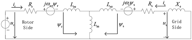
Figure 2. Equivalent circuit of a DFIG after the fault.
Eliminating the rotor current in Equation (2), the stator flux linkage ψs can be obtained in Equation (3):
where the terminal voltage is us = isXe, then the stator flux linkage ψs in Equation (3) is put into Equation (1):
In the transient process of a DFIG, a component of the short-circuit current generated by dψs/dt (the transient of the stator flux linkage) is a DC attenuation component. Therefore, when analyzing the fundamental frequency component of the short-circuit current, which is caused by continuous excitation, the influence of stator flux linkage transients can be ignored (Sulla et al., 2011; Swain and Ray, 2017). Assuming that the equivalent potential of a DFIG is , and transient reactance is . A simplified diagram of the transient equivalent circuit of a DFIG after the fault can be obtained, as shown in Figure 3.

Figure 3. Simplified equivalent circuit of DFIG.
Simplifying Equation (4), the short-circuit current of a DFIG can be obtained during the fault:
From Equation (5), it can be seen that the short-circuit current of a DFIG can be obtained from E′, Rs, X′, and Xe, where Rs, X′, and Xe are the known quantities. Since the equivalent potential of a DFIG is , the short-circuit current is the same as the change law of the rotor flux linkage ψr after the fault. Then, the short-circuit current attenuates according to the rotor time constant τr after the fault. Among them, τr is the rotor time constant . From the above analysis, it can be seen that in order to calculate the short-circuit current during the entire fault period, the initial value and the steady-state value of the short-circuit current should be obtained firstly.
Calculation Method of DFIG Short-Circuit Current at the Initial Fault Time
The flux linkage is non-abrupt before and after the fault, so it can be seen that the stator flux dψs/dt = 0 at the initial time. Simplifying Equation (4), and the short-circuit current at the initial moment can be obtained:
As it can be seen from Equation (6), the initial short-circuit current of a DFIG can be obtained by Rs, ψr0, Xe, and X′, among them, Rs, X′, and Xe are the known quantities.
Because the rotor flux is also non-abrupt at the moment of failure, the initial value of the rotor flux ψr0 can be obtained from the pre-fault working conditions. Before the fault occurs, the output active and the reactive power of a DFIG are:
In Equation (7), isq and isd are the active and reactive components of the stator current before the fault; P0 and Q0 are the output active and reactive power of a DFIG before the fault; usq is the q-axis component of the stator voltage. As the rotor-side converter of a DFIG adopts the stator flux orientation, namely: , ψsd = 0, and Equation (8) can be obtained:
Combining Equations (7, 8), the rotor current can be eliminated. The rotor flux at the initial moment can be obtained by the output active and reactive power of a DFIG and the voltage before the fault.
In Equation (9), ψrq0 and ψrd0 are the q-axis and d-axis components of the rotor flux before the fault. According to Equation (9), the rotor flux can be obtained by P0, Q0, us0 at the initial moment of fault. Among them, the active and reactive power are determined by the working conditions before the failure. And the stator voltage is close to the rated value before the fault. Therefore, the short-circuit current at the initial fault time can be obtained in Equation (10):
Calculation Method of DFIG Short-Circuit Current at the Steady State
Based on China's grid-connected standard, the rotor converter needs to adjust the rotor current according to voltage drop degree. Therefore, the rotor excitation current will change before and after the fault, which will affect the output characteristics of short-circuit current.
In previous research, it was considered that the input was the Crowbar of a DFIG and the converter was locked. And the short-circuit current of a DFIG would reduce to zero. Under the new grid-connected standard, the rotor-side converter will provide continuous excitation current during the fault. In this situation, the short-circuit current of a DFIG will not reduce to zero, but the continuous short-circuit current will be output.
If there is a fault at the power grid, the voltage drop of the machine will be detected by a DFIG. And the rotor converter will adjust the excitation current, according to the requirement of the new grid standard. Then, DFIG will output the reactive current, which can provide support for system voltage. Through a dynamic process, the rotor excitation current will reach the reference value under the new grid-connected standard.
When the dynamic process is over, the fault steady state will be reached, in which dψs/dt = 0. Simplifying Equation (1), the following equation can be obtained:
When the fault steady state is reached, the excitation current of the rotor converter ir attains ir∞ (the reference value of the excitation current in the new grid-connected standard), through the dynamic process. And at the moment, the stator current is also has reached is∞ (the steady-state short-circuit current). Combining Equations (1, 11), the following equation can be obtained:
In Equation (12), ir∞ is the rotor excitation current at the steady state, is∞ = irdref + jirqref, (irq_refand ird_ref are the reference value of active and reactive current of the rotor, respectively).
China has issued the new wind power grid-connected standard GB/T19963-2011 “Technical Regulations for Wind Farm Access to Power System.” In the standard, the output reactive power during the fault is demanded as shown in Equation (13):
In Equation (13), Kd is the gain coefficient of reactive current, irmax and irN are the maximum current and rated current of a rotor, respectively.
It can be seen from Equation (13) that the rotor converter gives priority to adjust the reactive current reference value ird_ref, during the fault. Its proportion is determined by the degree of voltage drop and the gain coefficient Kd. And the active current is determined by the output power and voltage before the rotor current surpasses the maximum current. Figure 4 shows the relationship between the reference value of reactive current and the degree of voltage drop during the fault.
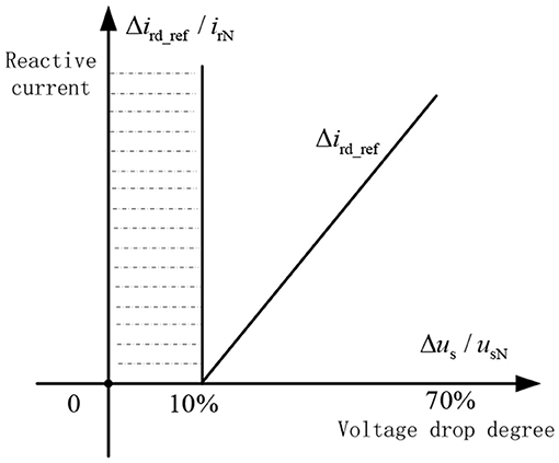
Figure 4. Relationship between the deviation of us and rotor reactive current.
Before the fault, the power factor of a DFIG is 1, ird0 = 0. Using Equations (12, 13), the steady-state short-circuit current of a DFIG under continuous excitation can be obtained:
In Equation (14), X is the steady-state stator reactance.
Experimental Results and Analysis
Based on RTDS, a digital-to-analog experimental platform for a DFIG with actual converter control units was established. Among them, the control units of the rotor converter are designed by using the field-programmable gate array (FPGA) chips, which are the controller core, the DFIG, and an RTDS-built grid model. The data transmission is realized through a parallel communication interface, which realizes the real-time control of the rotor converter.
In Figure 5, an actual DFIG wind farm connected to a grid was considered as an example to verify the experiment. The DFIG is connected to a 35-kV collector line through the transformer T2 at a terminal and is then connected to a 220-kV power system through the wind farm main transformer T1. There are 15 sets of 2.0-MW DFIG wind turbine generators in the DFIG wind farm. The stator and rotor resistances are 0.015 and 0.0099 p.u., respectively, and the stator and rotor leakage inductances are 0.168 and 0.152 p.u., respectively. The excitation mutual inductance is 3.49 p.u. The equivalent impedance of lines AB, BC, and DE is (1.95 + j5.53) Ω, (1.46 + j4.16) Ω, (0.13 + j0.11) Ω, and the system equivalent impedance is j0.5 Ω. Because the wind farm adopts the same type of the DFIG wind turbine in this paper, and the distance between the DFIGs is short, the transient characteristics of DFIGs are almost the same when they are faulty. The DFIGs on each collection line can be used instead by a single DFIG with equal capacity.
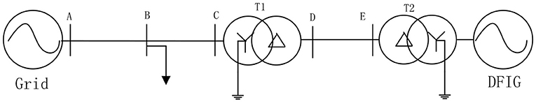
Figure 5. The grid structure with DFIG wind farms.
Assuming that a DFIG is working under rated operating conditions before the fault, a three-phase metal short-circuit fault occurs at the terminal B of the AB line at t = 0.5 s, and the fault lasting for 0.2 s. Firstly, the rotor excitation current of a DFIG under the new grid-connected standard has been analyzed. Figure 6A shows a comparison between the measured rotor current and reference rotor current when a three-phase metal short-circuit fault occurs at the terminal B.
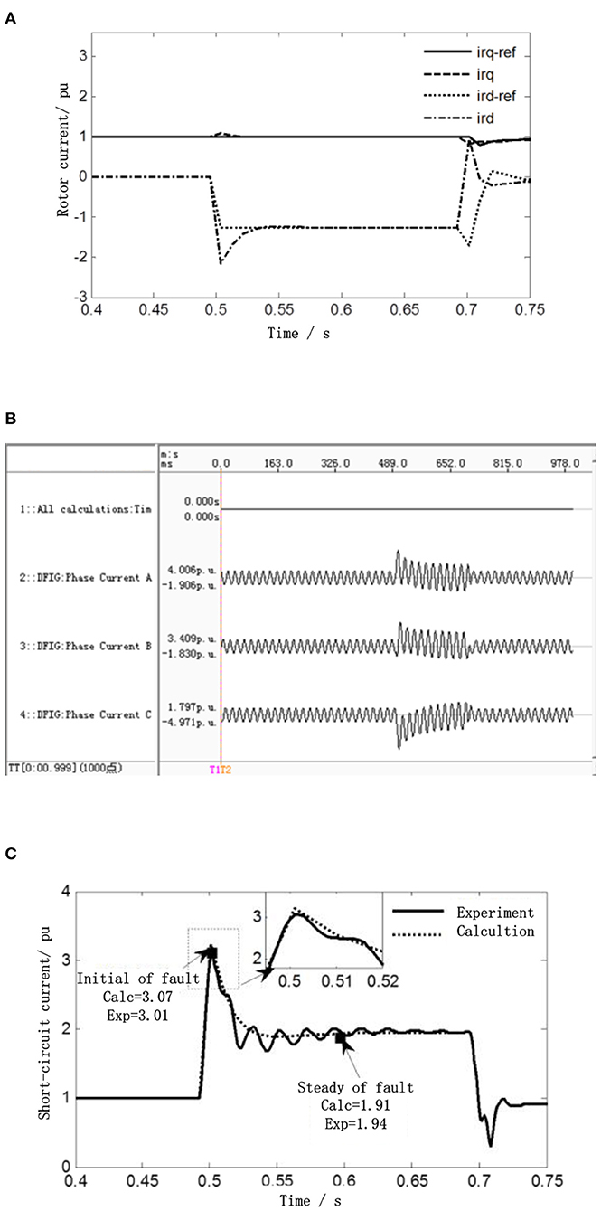
Figure 6. Comparison figure between the calculation result and experimental result of DFIG three-phase short circuit at bus B. (A) Comparison of the rotor current control reference value and actual rotor value. (B) Experimental result of short-circuit current of three-phase short-circuit DFIG at bus B under rated conditions. (C) Comparison of the calculation result and experimental result of root mean square (RMS) three-phase short circuit at bus B.
It can be seen from Figure 6A, after the fault occurs, the rotor excitation current reaches the reference value under the new grid-connected standard through the dynamic process, which is consistent with the result of an analysis in section Calculation Method of DFIG Short-Circuit Current at the Initial Fault Time. Figure 6B shows the experimental result of the short-circuit current of a DFIG, when a fault occurs at the terminal B. Due to the influence of continuous excitation current during the fault, a DFIG will output the steady-state short-circuit current, which is a big difference compared with the traditional DFIG. Using the full-cycle Fourier algorithm to extract the root mean square (RMS) of the short-circuit current, and the extracted RMS is shown in Figure 6C. In addition, the RMS of the short-circuit current is calculated by using the method proposed in this paper, which is also shown in Figure 6C.
It can be seen from Figure 6C, at the initial time of fault (t = 0.5 s), the RMS of the short-circuit current of a DFIG suddenly increases to 3.01 p.u., the calculation result obtained by using the proposed method is 3.07 p.u., and the error from the experimental result is 2.01%. After the fault reaches steady state, the experimental result is 1.94 p.u. The calculation result obtained by using the proposed method is 1.91 p.u., and the error from the experimental results is 1.6%. The similarity between the calculation results and the experimental results is extremely high during the attenuation period, and the extreme results fluctuate above and below the calculation result. From the above analysis, the proposed method not only accurately calculates the initial value and the steady-state value of the short-circuit current but also accurately describes the variation law of the short-circuit current in the attenuation process.
Assuming that a DFIG is working under 0.8 times of rated operating conditions before the fault, a three-phase metal short-circuit fault occurs at the terminal A of the AB line at t = 0.5 s, and the fault lasts for 0.2 s. Firstly, the rotor excitation current of a DFIG under the new grid-connected standard has been analyzed. Figure 7A shows a comparison between the measured rotor currents and reference rotor currents, when a three-phase metal short-circuit fault occurs at the terminal A.
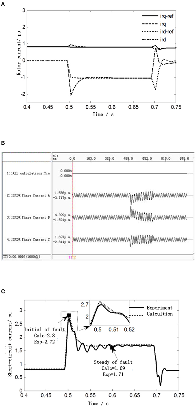
Figure 7. Comparison figure between the calculation result and experimental result of DFIG three-phase short circuit at bus A. (A) Comparison of the rotor current control reference value and actual rotor value. (B) Experimental result of short-circuit current of three-phase short-circuit DFIG at bus A under 0.8 rated conditions. (C) Comparison of the calculation result and experimental result of RMS three-phase short circuit at bus A.
Figure 7B shows the experimental result of the short-circuit current of a DFIG, when a fault occurs at the terminal A. Using the full-cycle Fourier algorithm to extract the RMS of the short-circuit current, and the extracted RMS is shown in Figure 7C. In addition, the RMS of the short-circuit current is calculated by using the method proposed in this paper, which is also shown in Figure 7C.
According to Figure 7C, at the initial time of fault (t = 0.5 s), the RMS of the short-circuit current of a DFIG suddenly increases to 2.72 p.u. The calculation result obtained by using the proposed method is 2.8 p.u., and the error from the experimental result is 2.9%. After the fault reaches steady state, the experimental result is 1.71 p.u. The calculation result obtained by using the proposed method is 1.69 p.u., and the error from the experimental results is 1.2%. From the above analysis, it can be seen that the proposed method has high accuracy in the calculation of the short-circuit currents, under different fault locations and under different working conditions.
About 24 sets of experimental tests were carried out, respectively, for different working conditions (the output power before the fault is 1, 0.9, 0.8, and 0.7 p.u.) and different fault locations (at 20, 30, 40, 50, 60, and 70% of line AB). The experimental results and the calculation results obtained by using the proposed method are shown in Figure 8. At the initial time (t = 0.5 s), steady-state time (t = 0.6 s), t = 0.52 s, and t = 0.55 s in the dynamic process, the errors between the calculation results and experimental results were compared. From Figure 8, it can be seen that the errors between the calculation results and experimental results at the initial time are < 3%, under different fault conditions. And the errors at steady-state time are < 2%. In the whole attenuation process, the errors between the calculation results and experimental results do not exceed 6%, which can correctly describe the change law of the short-circuit current of a DFIG.
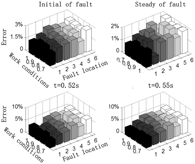
Figure 8. Comparison between the calculation result and experimental result of the short-circuit current.
Conclusion
In previous research, the problem of continuous excitation was not considered. To solve the problem, a DFIG transient equivalent model under the condition of continuous excitation is established. According to a non-abrupt change of flux linkage and the China's new grid standard, the short-circuit current calculation method of a DFIG under continuous excitation condition is put forward. The experimental results of an RTDS experimental platform show that:
(1) In this paper, the characters of the equivalent potential of a DFIG are analyzed during the fault period. And the DFIG transient equivalent model under the constant excitation is established, which describes the transient process of a DFIG accurately.
(2) The requirements of reactive power in the China's new grid-connected standard are analyzed, and the short-circuit current calculation method of a DFIG under the condition of continuous excitation is put forward. The proposed method not only accurately calculates the initial value and steady-state value of short-circuit current, but also accurately describes the change law of short-circuit current, which is verified by the experimental result.
Data Availability Statement
The original contributions presented in the study are included in the article/supplementary material, further inquiries can be directed to the corresponding author/s.
Author Contributions
JY: data curation, writing, and software.
Funding
This work was supported by the key scientific research projects of colleges and universities in Henan Province (19A470003).
Conflict of Interest
The author declares that the research was conducted in the absence of any commercial or financial relationships that could be construed as a potential conflict of interest.
References
Duan, J., Chen, T., Shang, D., Cui, S., and He, Y. (2020). Current attenuation factor based line protection scheme for distribution network of DFIG wind power integration system. Proc. CSEE 40, 1915–1924. doi: 10.13334/j.0258-8013.pcsee.X190386
Firouzi, M., and Gharehpetian, G. (2017). LVRT performance enhancement of DFIG-based wind farms by capacitive bridge-type fault current limiter. IEEE Trans. Sustain. Energy 9, 1118–1125. doi: 10.1109/TSTE.2017.2771321
Garibay, A., Rodriguez, J., and Correa, J. (2018). Analysis of rotor current impact on DFIG-WECS under fault condition. IEEE Latin Am. Trans. 16, 329–334. doi: 10.1109/TLA.2018.8327383
Haj-Ahmed, M. A., Feilat, E. A., Khasawneh, H. J., Abdelhadi, A. F., and Awwad, A. (2018). Comprehensive protection schemes for different types of wind generators. IEEE Trans. Ind. Appl. 54, 2051–2058. doi: 10.1109/TIA.2018.2789865
Liu, T., Zhang, Y., Wang, M., Zhang, Y., Qin, X., and Wang, Y. (2020). Short-circuit current calculation method of doubly fed induction generator considering control strategy switching. Proc. CSEE 40, 17–25. doi: 10.13334/j.0258-8013.pcsee.200890
Muljadi, E., Samaan, N., Gevorgian, V., Li, J., and Pasupulati, S. (2013). Different factors affecting short circuit behavior of a wind power plant. IEEE Trans. Ind. Appl. 49, 284–292. doi: 10.1109/TIA.2012.2228831
National Electricity Regulatory Standardization Technical Committee. (2011). GBT_19963-2011 Technical Rule for Connecting Wind Farm to Power System. Beijing: Standard Press of China.
Ouyang, J., Tang, T., Zheng, D., Ren, W., Xiong, X., and Zhong, J. (2017). Characteristics and calculation method of short-circuit current of doubly fed wind generator under lower voltage ride through. Trans. China Electrotech. Soc. 32, 216–224. doi: 10.19595/j.cnki.1000-6753.tces.160823
Pan, W., Liu, M., Zhao, K., Zhang, Y., and Liu, T. (2019). A practical short-circuit current calculation method for DFIG-based wind farm considering voltage distribution. IEEE Access 7, 31774–31781. doi: 10.1109/ACCESS.2019.2902848
Rahimi, M., and Azizi, A. (2019). Transient behavior representation, contribution to fault current assessment, and transient response improvement in DFIG based wind turbines assisted with crowbar hardware. Int. Trans. Electr. Energy Syst. 29:e2698. doi: 10.1002/etep.2698
Sulla, F., Svensson, J., and Samuelsson, O. (2011). Symmetrical and unsymmetrical short-circuit current of squirrel cage and doubly fed induction generators. Electr. Power Syst. Res. 8, 1610–1618. doi: 10.1016/j.epsr.2011.03.016
Swain, S., and Ray, P. K. (2017). Short circuit fault analysis in a grid connected DFIG based wind energy system with active crowbar protection circuit for ridethrough capability and power quality improvement. Int. J. Electr. Power Energy Syst. 84, 64–75. doi: 10.1016/j.ijepes.2016.05.006
Tamaarat, A., and Benakcha, A. (2014). Performance of PI controller for control of active and reactive power in DFIG operating in a grid-connected variable speed wind energy conversion system. Front. Energy 8, 371–378. doi: 10.1007/s11708-014-0318-6
Telukunta, V., Pradhan, J., Agrawal, A., Singh, M., and Srivani, S. G. (2018). Protection challenges under bulk penetration of renewable energy resources in power systems: a review. CSEE J. Power Energy Syst. 3, 365–379. doi: 10.17775/CSEEJPES.2017.00030
Wang, Z., Liu, Y., Lei, M., Bian, S., and Shi, Y. (2015). Doubly-fed induction generator wind farm aggregated model based on crowbar and integration simulation analysis. Trans. China Electrotech. Soc. 30, 45–52. doi: 10.19595/j.cnki.1000-6753.tces.2015.04.006
Keywords: DFIG, short-circuit current, fault analysis, relay protection, rotor excitation
Citation: Yin J (2021) Improved Short-Circuit Current Calculation of Doubly Fed Wind Turbines With Uninterrupted Excitation. Front. Energy Res. 9:686138. doi: 10.3389/fenrg.2021.686138
Received: 26 March 2021; Accepted: 13 April 2021;
Published: 20 May 2021.
Edited by:
Liang Chen, Nanjing University of Information Science and Technology, ChinaReviewed by:
Yunbing Wei, Shanghai University of Engineering Sciences, ChinaXiangqian Zhu, Zhengzhou University of Light Industry, China
Copyright © 2021 Yin. This is an open-access article distributed under the terms of the Creative Commons Attribution License (CC BY). The use, distribution or reproduction in other forums is permitted, provided the original author(s) and the copyright owner(s) are credited and that the original publication in this journal is cited, in accordance with accepted academic practice. No use, distribution or reproduction is permitted which does not comply with these terms.
*Correspondence: Jun Yin, eWluanVuMDM3MUAxMjYuY29t