 Jun Yin
- School of Electric Power, North China University of Water Resources and Electric Power, Zhengzhou, China
With the enlarging scale of doubly-fed induction generators (DFIGs) connected to power systems, it is important to analyze the influence of a short-circuit current to system relay protection. Due to the correct evaluation of the protection operation characteristics, the DFIG short-circuit current needs to be calculated accurately. But the current research on the short-circuit current of DFIG is based on the following assumption: the rotor excitation current is zero after the rotor crowbar is put, and the influence of its dynamic process is ignored. This will bring errors to the calculation results. This paper takes into account the influence of rotor current dynamics by studying the mechanism of the potential transient change of DFIG. The stator rotor flux linkage of DFIG in the event of a three-phase short-circuit is accurately calculated, and an improved RMS calculation method of doubly-fed wind turbine short circuit current is proposed. A physical experiment platform with an actual controller of a doubly-fed fan is established, based on RTDS. It can be seen from the experiment that the short-circuit current calculation method proposed in this paper is more accurate than those methods that ignore the rotor dynamic process. This study lays a foundation for further study of the influence of DFIG on the protection operation characteristics.
Introduction
In recent years, the wind power in the world has developed rapidly. Since 2010, China has become the country with the largest installed capacity of wind power. Especially in Inner Mongolia, Gansu, and Liaoning Province, wind power has developed rapidly. However, large-scale wind power access to the power grid has made a great influence, and the impact of grid-connected wind power on relay protection has become a major concern in the current power system field.
DFIG are widely used in wind farms as their main turbines, because of the advantages of the wide range of operating wind speeds and the decoupled control of active and reactive power (Tamaarat and Benakcha, 2014; Firouzi and Gharehpetian, 2017; Sun and Wang, 2018; Okedu, and Barghash, 2020). However, with the increase of DFIG, the influence of the transient process of DFIG on the short-circuit current calculation cannot be ignored. Inaccurate calculation of the short-circuit current will cause deviation in the protection setting, affect the accuracy of the protection, and even cause the phenomenon of protection rejection or mis-operation in severe cases. Therefore, in order to improve the accuracy of the protection action, it is necessary to study the methods of short-circuit current calculation of DFIG thoroughly.
At present, there are some works of literature studying the short-circuit current calculation after the DFIG connected to the grid on different perspectives. In the literature (Howard, et al., 2012; Muljadi et al., 2013; Liu et al., 2018; Telukunta et al., 2018), in the no-load case, when the three-phase metallic short-circuit occurred, the crowbar was input. DFIG was equivalent to an asynchronous generator, and the rotor excitation current was assumed to be zero. A simplified short-circuit current calculation formula was presented in this paper. The method in this paper simply assumes that the rotor current after the Crowbar is accessed is zero, ignoring the dynamic process of the rotor current, and this method does not match the actual rotor current after a short-circuit fault.
In the literature (Sulla, et al., 2011; Zhai, et al., 2013; Wang et al., 2015; Fu et al., 2017; Rahimi and Azizi, 2019), the flux linkage of the stator was solved simply after the faults at different positions, and in this paper the calculation formula of the DFIG short-circuit current was given under different drop degrees of the terminal voltage, further. However, this method does not take into account rotor current dynamic process effects. Actually, after the fault of the power grid, the crowbar will be input to protect the rotor converter. However, the rotor flux cannot be mutated at the moment of the fault, as the rotor winding will induce a big rotor current. The rotor current may reach three to five times that of the rated value, and decay to zero gradually after 30–50 milliseconds. Ignoring the dynamic process of the rotor current will cause a certain error in the calculation result of the short circuit current, and it will affect the accuracy of the current protection of the collector line. Therefore, this paper presents an accurate calculation method of a DFIG short-circuit current, which accounts for the dynamic process of the rotor current.
In this paper, from the perspective of the mechanism of the DFIG’s transient potential, the stator flux linkage of the DFIG in a three-phase short circuit is calculated. The influence of rotor current dynamics is taken into account, and an improved method of the short-circuit current of the DFIG is proposed. In order to verify the correctness of the calculation method, a physical experiment platform with an actual controller of the DFIG current transformer is established based on the RTDS. The experimental results show that the short-circuit current calculation method proposed in this paper is more accurate, compared with the methods which ignore the dynamic process of the rotor. This study lays a foundation for further research on the influence of the DFIG’s short-circuit current on the protection operation characteristics.
DFIG Electromagnetic Transient Process
Figure 1 shows the main circuit topology of a grid-connected DFIG with a rotor Crowbar circuit. The DFIG is connected to the power grid by the collector line. The main protection on the collector line is a three-section current protection. For accurate evaluation of the current protection action, the key is accurately calculating the short-circuit current, which is provided to the collector wire by the DFIG, after the fault occurs.
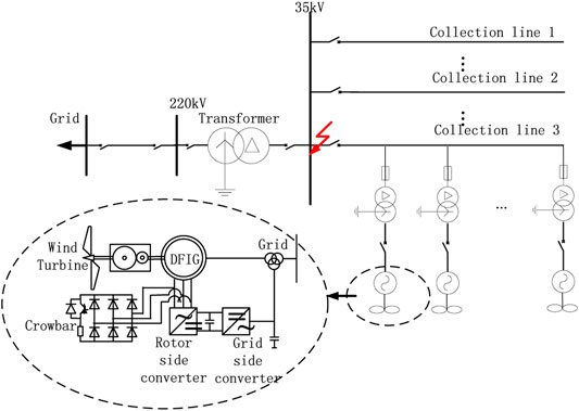
FIGURE 1. Circuit structure of DFIG wind farm.
Because the fault of the power grid will cause the electromagnetic transience of the DFIG, the electromagnetic transient process will cause the DFIG to output a big short-circuit current. Therefore, in order to calculate the short-circuit current accurately, the electromagnetic transient process of DFIG after the fault should be analyzed first. That means the relationship among the short-circuit current, the transient reactance, and the equivalent potential of DFIG should be obtained.
Ignoring the phenomenon of magnetic saturation, assuming the rotor speed does not change in transient process.
The mathematical model of the DFIG in the form of space vectors in the synchronous rotating coordinate system is (Muljadi et al., 2013):
Where, us, ur, is, ir, ψs, ψr are the stator voltage, rotor voltage, current and flux, which are converted to the stator side, respectively. Ls, Lr, Lm are the stator and rotor inductance, mutual inductance, respectively. Lsσ, Lrσ are the stator leakage, rotor leakage, Rs, Rr, Rcb are the rotor resistance and the rotor Crowbar resistance, ωs is the synchronous speed, and ωs-r is the slip speed.
During normal operation, the DFIG is excited by a rotor converter. When the power grid fails, the voltage of the DFIG drops suddenly, and a large transient voltage and current are induced in the rotor windings. The rotor winding should input the Crowbar to suppress the transient current and protect the converter from damage.
When a three-phase metallic short-circuit fault occurs in the power grid, assuming that the line reactance of the DFIG to the short-circuit point is Xe, the terminal voltage is
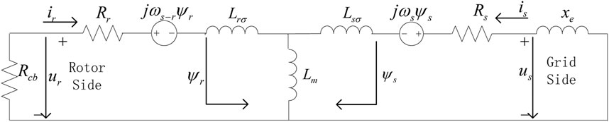
FIGURE 2. Fault equivalent circuit of DFIG wind power generator.
By eliminating the rotor current in Eq. 2, the stator flux linkage ψs can be obtained, then ψs is put into the Eq. 1:
Assuming that the DFIG’s equivalent potential is
From the above analysis, the short-circuit current of the DFIG is determined by E′, Rs, X′, and Xe. Among them, Rs, X′, and Xe are known quantities. Therefore, to calculate the short-circuit current of the DFIG accurately, it is required to solve the equivalent potential E’ after the DFIG fault occurred.
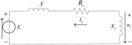
FIGURE 3. Simplified equivalent circuit of DFIG.
Calculation Method of DFIG Short-Circuit Current Considering the Dynamic Process of the Rotor Current
The equivalent potential of the DFIG is determined by its rotor flux linkage. Therefore, the key issue in studying the change law of the DFIG equivalent potential E', is how to accurately solve the rotor flux linkage during the fault.
Figure 4 shows the dynamic process of the DFIG rotor current after a three-phase short circuit. When the fault occurs, the rotor Crowbar is input and the rotor excitation circuit is shorted. The rotor current will increase to three to five times its rated value at first, and then decay to zero gradually after 30–50 milliseconds, which is similar to what is shown in Figure 4. However, compared with the traditional short-circuit calculation methods, the traditional methods ignore the rotor current dynamic, and assume the rotor current decays to zero directly after the fault occurs. Although the traditional method is convenient for calculation, it cannot accurately reflect the rotor current dynamic in the actual physical process and will cause certain errors in the calculation of the short-circuit current.
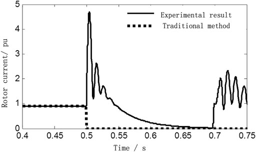
FIGURE 4. The rotor current dynamic process of DFIG under three phase short circuit.
In this section, in order to ensure the accuracy of the rotor flux linkage solution, the dynamic process of the rotor current is taken into account, which was ignored before. And the equivalent potential is calculated. Finally, it is input to Eq. 4, and the accurate short-circuit current is obtained.
From Eq. 2, the stator rotor current is represented by flux linkage:
Among them:
Bring Eq. 5 into Eq. 1, to get detailed stator rotor flux linkage, which considering the rotor dynamics:
In the process of solving Eq. 6, us, ur, Ls, Lr, Lm, Rs, Rr are all known quantities. Therefore, Eq. 6 is a first-order ordinary differential equation group about the stator rotor flux linkage. The Laplace transform method is used to solve the Eq. 6:
Among them,
When a three-phase metal fault occurs at the machine terminal of the DFIG, the rotor Crowbar is input. Due to the short delay time of the converter control, if the delay time is ignored, that is ur is 0 after the Crowbar is input, so it can be obtained from Eq. 7 that:
Among them:
Solve the time domain solution of Eq. 8:
Among them:
In the synchronous coordinate system, the two parts of the rotor flux linkage attenuated at frequencies close to the DC and rotor speed, respectively. The initial stator rotor flux ψs(0), ψr(0) can be obtained by the pre-fault voltage and current through the voltage Eq. 1.
From Eq. 4, the amplitude of the fundamental frequency AC component in the equivalent potential is:
The fundamental frequency RMS calculation method for the short-circuit current of the DFIG is in Eq. 11:
The formula of the rotor flux linkage after faults in traditional studies is in Eq. 12:
Comparing Eq. 9 with Eq. 12, the traditional studies used a simplified calculation method, which ignored the rotor current Ir and the stator resistance Rs. Although the obtained rotor flux linkage also includes the rotor speed attenuation part in the traditional method, the proposed method introduces
Experimental Results and Analysis
Based on RTDS (real time digital simulation equipment of power system), an experimental platform with a DFIG converter actual control unit is established. The IGBT module is used to build the converter control unit. In the experimental platform, the parallel communication interface is used to realize the real-time transmission of the control data. The IGBT module is used to real-time control the rotor converter. The system structure diagram of the experimental platform built in this paper and the experimental scenario are shown in Figure 5.
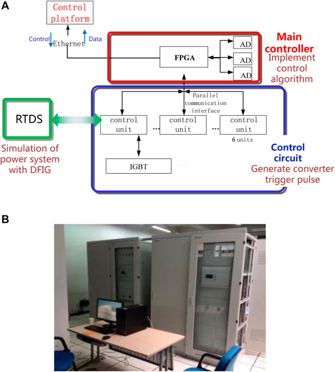
FIGURE 5. Physical experiment equipment of DFIG based on RTDS. (A) System structure of experiment equipment. (B) Physical experiment equipment figure.
Take the example of an actual DFIG farm connected to the grid in Figure 6. DFIGs are connected to 35 kv collection line through a transformer at the machine terminal. The lengths of lines AB and CD are 20 and 10 km respectively. The main relevant experiment parameters are as follows: the transformation ratios of the main transformer and machine terminal transformer are 220/35 kV, 35/0.69 kV respectively; The DFIG rated capacity is 2.0 MW; Stator resistance and leakage inductance are 0.016 p.u., 0.169 p.u. respectively; rotor resistance and leakage inductance are 0.009 p.u, 0.153 p.u respectively; excitation mutual inductance is 3.49 p.u.; the Crowbar resistance is 0.1 p.u. There are 10 identical DFIGs on each collection line in the DFIG farm.
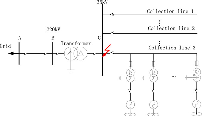
FIGURE 6. Fault testing circuit structure of DFIG wind farm.
Because the circuit between the wind turbines is short, on the same collection line, its influence can be ignored. On each collection line, the transient characteristics of wind turbines are almost the same, so the wind turbines on each collection line can be instead replaced by a single DFIG with equal capacity.
Assuming the DFIG is working under rated operating conditions, a three-phase metal short-circuit fault occurs at the C terminal of the CD line at t = 0.5 s, and the fault lasts for 0.2 s. Figure 7 shows the instantaneous value of the three-phase short-circuit current of DFIG at terminals C, which is obtained during the experimental test. The RMS of the short-circuit current is extracted via the full-cycle Fourier algorithm, which is the solid line shown in Figure 8.
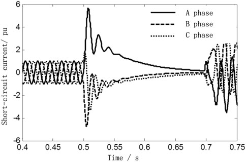
FIGURE 7. DFIG short circuit current value of three-phase short circuit at bus C under rated operating conditions.
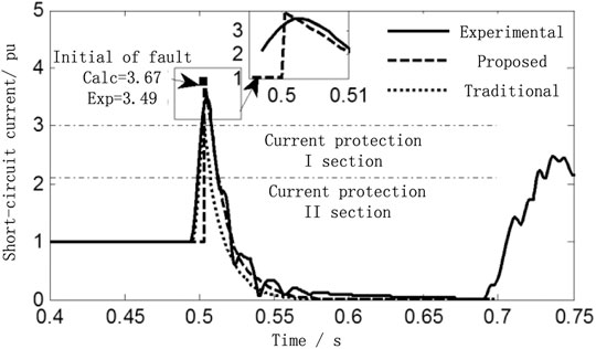
FIGURE 8. Comparison figure between calculation result and experimental result of DFIG three-phase short circuit at bus C.
Under the same conditions, MATLAB was used to calculate the short-circuit current RMS of the traditional method and the proposed method. Compared with the traditional calculation method, the proposed method and the short-circuit current RMS were measured by the experimental platform, and the short-circuit current calculation errors under the two methods were analyzed. Figure 8 shows the trajectory of the DFIG short-circuit current RMS at terminal C, obtained by the traditional method, the proposed method, and the result of the experimental platform. Figure 9 is the comparison of the short circuit current calculation errors between the traditional method and the proposed method in this paper.
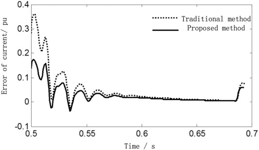
FIGURE 9. Short circuit current error comparison between the traditional method and proposed method.
It can be seen from the experimental results in Figure 8, when the fault occurs at 0.5 s, the RMS of the DFIG short-circuit current suddenly increases to 3.49 times of the rated value. The calculated result of the proposed method is 3.67 p.u., and the error is 5.1%, compared with the experimental test result. The result of the traditional method is 3.15 p.u., which ignores the rotor dynamic current. And the error of the traditional method is 9.7%, compared with the experimental test result. From the above analysis, the accuracy of the proposed method in this paper is improved by 4.6%, especially from the 0.5 s to the 0.55 s(short circuit current attenuation process). The curves fitting the degree between the proposed method calculation result and the experimental test result is extremely approach.
Comparing the fixed value of the I section current protection of the collector circuit in Figure 8, the calculation results of the traditional method may wrongly analyze the characteristics of the protection operation, resulting in the increase of protection rejection and mis-operation. However, the proposed method in this paper can be more accurate to analyze the effect of the DFIG short-circuit current, on the current protection operating characteristics of the collector circuit.
It can be seen from Figure 9, the error curve of proposed method is always below the error curve of the traditional method, and the error of proposed method in this paper is less than 0.19 p.u. (the calculation error is 6%) in the whole process.
After 20 sets of experiments, a large amount of experimental data was obtained, and the short-circuit current calculation results and experimental test result data are shown in Table 1. The average error and the maximum error of the short-circuit current are calculated, at 0, 10, 20, and 50 ms after the fault.
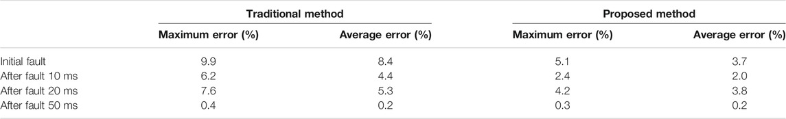
TABLE 1. Comparison between proposed method calculation result and experimental result with 20 sets of experiments.
From Table 1, it can be seen that the accuracy of the method proposed in this paper is improved by 2–5% compared with the traditional calculation method, and during the fault, the error between the proposed method calculation result and experimental result does not exceed 6%. It can be concluded that the calculation method proposed in this paper can not only calculate the initial value of the short-circuit current more accurately, but also reveal the variation law of the whole attenuation process of the short-circuit current more accurately.
Conclusion
In order to correctly evaluate the protective action characteristics of the large-scale DFIG accessing to the grid, the influence of the dynamic process of rotor current is taken into account in short-circuit current calculation. The rotor flux of DFIG in the event of a short circuit is calculated accurately, an improved RMS calculation method of DFIG short-circuit current is proposed, and an experimental platform is established. Based on the experimental platform, the accuracy of the short-circuit current calculation result is compared, between the traditional calculation method and the method proposed in this paper.
The experimental results show that, compared with the previous researches, the influence of the rotor current dynamic process on the flux linkage calculation is taken into account, in the RMS calculation method of the short-circuit current proposed in this paper. The method proposed in this paper can more accurately calculate the equivalent potential, which is composed of flux linkage. The calculated initial value of the short-circuit current and the dynamic path of the short-circuit current have higher accuracy, in the proposed method. This study lays the foundation for further study of the influence of the DFIG short-circuit current on the protection operation characteristics.
Data Availability Statement
The original contributions presented in the study are included in the article/Supplementary Material, further inquiries can be directed to the corresponding author.
Author Contributions
JY: data curation, writing, and software.
Funding
This work is supported by the Key scientific research projects of colleges and universities in Henan Province (19A470003).
Conflict of Interest
The author declares that the research was conducted in the absence of any commercial or financial relationships that could be construed as a potential conflict of interest.
References
Firouzi, M., and Gharehpetian, G. (2017). LVRT Performance Enhancement of DFIG-Based Wind Farms by Capacitive Bridge-type Fault Current Limiter. IEEE Trans. Sustain. Energ. 9 (3), 1118–1125. doi:10.1109/TSTE.2017.2771321
Fu, Y., Li, Y., He, X., and Han, P. (2017). Corrected Transient Analysis Model of Doubly Fed Induction Generator with Crowbar Protection under Grid Fault. Proc. CSEE 37 (16), 4501–4602. doi:10.13334/j.0258-8013.pcsee.1612
Howard, D. F., Habetler, T. G., and Harley, R. G. (2012). Improved Sequence Network Model of Wind Turbine Generators for Short-Circuit Studies. IEEE Trans. Energ. Convers. 27 (4), 968–977. doi:10.1109/tec.2012.2213255
Liu, M., Pan, W., and Yang, G. (2018). Practical Calculation Method of Short-Circuit Currents Contributed by Doubly-Fed Wind Turbine Cluster. Power Syst. Technology 42 (5), 1475–1481.
Ma, J., and Liu, J. (2018). Adaptive Directional Current protection Scheme Based on Steady State Component in Distribution Network with DG. Electric Power Automation Equipment 38 (1), 1–9.
Muljadi, E., Samaan, N., Gevorgian, V., Li, J., and Pasupulati, S. (2013). Different Factors Affecting Short Circuit Behavior of a Wind Power Plant. IEEE Trans. Ind. Applicat. 49 (1), 284–292. doi:10.1109/tia.2012.2228831
Okedu, K., and Barghash, H. (2020). Enhancing the Performance of DFIG Wind Turbines Considering Excitation Parameters of the Insulated Gate Bipolar Transistors and a New PLL Scheme. Front. Energ. Res. 8, 373. doi:10.3389/fenrg.2020.620277
Rahimi, M., and Azizi, A. (2019). Transient Behavior Representation, Contribution to Fault Current Assessment, and Transient Response Improvement in DFIG-Based Wind Turbines Assisted with Crowbar Hardware. Int. Trans. Electr. Energ Syst. 29 (1), e2698. doi:10.1002/etep.2698
Sulla, F., Svensson, J., and Samuelsson, O. (2011). Symmetrical and Unsymmetrical Short-Circuit Current of Squirrel Cage and Doubly Fed Induction Generators. Electric Power Syst. Res. 8 (1), 1610–1618. doi:10.1016/j.epsr.2011.03.016
Sun, L., and Wang, Y. (2018). LV Ride through Control Strategy of Doubly Fed Induction Generator Based on Crowbar Series Capacitor. Power Syst. Technology 42 (7), 2089–2096.
Swain, S., and Ray, P. K. (2017). Short Circuit Fault Analysis in a Grid Connected DFIG Based Wind Energy System with Active Crowbar protection Circuit for Ridethrough Capability and Power Quality Improvement. Int. J. Electr. Power Energ. Syst. 84, 64–75. doi:10.1016/j.ijepes.2016.05.006
Tamaarat, A., and Benakcha, A. (2014). Performance of PI Controller for Control of Active and Reactive Power in DFIG Operating in a Grid-Connected Variable Speed Wind Energy Conversion System. Front. Energ. 8 (3), 371–378. doi:10.1007/s11708-014-0318-6
Telukunta, V., Pradhan, J., Agrawal, A., Singh, M., and Srivani, S. (2018). Protection Challenges under Bulk Penetration of Renewable Energy Resources in Power Systems: A Review. CSEE J. Power Energ. Syst. 3 (4), 365–379. doi:10.17775/CSEEJPES.2017.00030
Wang, Z., Liu, Y., Lei, M., Bian, S., and Shi, Y. (2015). Doubly-Fed Induction Generator Wind Farm Aggregated Model Based on Crowbar and Integration Simulation Analysis. Trans. China Electrotechnical Soc. 30 (4), 45–52. doi:10.19595/j.cnki.1000-6753.tces.2015.04.006
Keywords: DFIG, short circuit current, fault analysis, relay protection, rotor dynamic process
Citation: Yin J (2021) Research on Short-Circuit Current Calculation Method of Doubly-Fed Wind Turbines Considering Rotor Dynamic Process. Front. Energy Res. 9:686146. doi: 10.3389/fenrg.2021.686146
Received: 26 March 2021; Accepted: 21 April 2021;
Published: 28 May 2021.
Edited by:
Liang Chen, Nanjing University of Information Science and Technology, ChinaReviewed by:
You Zhou, Changsha University of Science and Technology, ChinaJianhui Meng, North China Electric Power University, China
Copyright © 2021 Yin. This is an open-access article distributed under the terms of the Creative Commons Attribution License (CC BY). The use, distribution or reproduction in other forums is permitted, provided the original author(s) and the copyright owner(s) are credited and that the original publication in this journal is cited, in accordance with accepted academic practice. No use, distribution or reproduction is permitted which does not comply with these terms.
*Correspondence: Jun Yin, eWluanVuMDM3MUAxMjYuY29t