 D. Liang
 Y. Li1
 Z. Zhou
 P. Wiśniewski
- 1School of Electrical and Power Engineering, China University of Mining and Technology, Xuzhou, China
- 2Department of Power Engineering and Turbomachinery, Silesian University of Technology, Gliwice, Poland
Flow separation commonly affects the stability of turbomachines, especially under low-flowrate conditions. Compared with conventional blades, a forward-swept blade is more efficient at high flowrates. However, experiments and numerical simulations show that a forward-swept blade produces an unstable region under low flowrate. In this paper, the topological analysis is used to analyze the structure and size of flow separation in forward swept blades. Three-dimensional structure and formation mechanism of vortices in forward-swept blades are analyzed using the cross-section flow pattern method. For forward-swept blades, flow separation mainly occurs at the blade tip and corner, accompanied by clear velocity fluctuations, the break-up of shed vortices, and diffusion. With decreasing flowrate, the shedding vortices move forward and the speed of vortex annihilation gradually decreases. In addition, the number of singularities in the rotor passage increases with the decrease of flow rate, and the region affected by shedding vortex increases. The rotating direction of internal vortex in turbomachinery is fixed. The pressure surface, passage vortex, and concentrated shedding vortex were found to rotate clockwise, whereas the suction surface, corner vortex, and shedding vortex rotate in a counterclockwise direction.
Introduction
With the development of manufacturing technology and numerical analysis software, three-dimensional blades are being increasingly used in axial turbomachines. Since the 1960s, the blade curve formation theory proposed by References (Filippov and Wang, 1962; Wang et al., 1981; Wang, 1999) has provided theoretical guidance for the design of three-dimensional blades. More recently, forward-swept blades have been mentioned (Wennerstrom and Puterbaugh, 1984; Wennerstrom, 1990) in the context of experimental transonic compressors. Experimental results show that forward-swept blades maintain high efficiency at the tip of the cascade at high speeds. Mohammed and Raj (1977) designed forward-swept blades for a low-speed compressor rotor, optimizing the flow separation at the tip of the suction surface and improving the characteristics of the compressor. Vad et al. (2015) comprehensively described the characteristics of forward-swept blades. Combining straight blades and forward-swept blades can increase the efficiency of the fan by 2–3%, although for free-vortex rotors, there is little improvement in efficiency(He et al., 2018; Kaya et al., 2018).
Flow separation, which frequently occurs in the flow around various objects, is a complex flow phenomenon in fluid mechanics, and has been extensively studied along with its associated flow characteristics. Three-dimensional flow separation theory, first proposed by Maskell (1955) and Lighthill (1963), represents the cornerstone of such studies. Thereafter, bubble separation, free vortex separation, open separation, and closed separation configurations were investigated. References (Zhang and Deng, 1992; Zhang, 1994; Zhang, 1997) obtained the flow distributions of multiple cross-sections from experiments and calculations, and derived distribution rules for semi-singularities on cross-sectional contour lines and topological rules for determining the total number of different flows. Surana et al. (2006) developed a three-dimensional steady separation and reattachment theory using nonlinear dynamical systems, and obtained the separation point and separation line criteria under no-slip boundary conditions in a compressible flow. Gbadebo et al. (2005) adopted the limit streamline topology method and nonlinear dynamics to obtain the relationship between the inlet angle, boundary layer, and separation point. This method provided a new way of interpreting and researching flow separation theory.
The internal flow, boundary layer separation, and stall/instability conditions of turbomachines can be studied using experimental methods and numerical simulations. Karyakin et al. (2018); Zhang et al. (2018) used the tuft method and oil-flow method, respectively, to conduct experiments on flow separation control around isolated airfoils. However, few studies have applied these experimental methods to rotor flow separation. Taking the oil-flow method as an example, the uniform paint applied on the blade is subjected to two forces, namely the shear force from the airflow and the inertial centrifugal force
Numerical simulations and experimental methods cannot, however, fully explain the law of flow separation, especially for forward-swept blade flow separation, which is still at the early stages of investigation. In this paper, the Navier–Stokes equations for internal flow in turbomachines are analyzed and the flow field on the blade surface of a forward-swept fan is investigated. The singularity characteristics of the blade surface separation are analyzed using a topological approach. The flow separation is explored in three-dimensional space using a topological-mapping method. The aim of this work is to determine the influence of forward-swept blades on the flow separation of axial flow turbomachines, and to provide a foundation for studying the control of flow separation.
Mathematical Model
In the study of Lighthill (1963), the limit streamline is equal to the friction line:
As can be seen from Eq. 1, the direction of the limit streamline is the same as that of the friction line. The limit streamline and the friction line are considered to be equivalent in most studies. In cascade experiments, the oil-flow method and the surface silk-line method can reveal the boundary layer flow state to an adequate degree of accuracy. The frictional line can be transformed into:
According to the theory of phase-plane analysis for ordinary differential equations, the shape and type of friction lines at critical points depend on the properties of the eigenvalues of the 2 × 2 Jacobian matrix. The critical points can be classified by the surface streamlines nearby, which are determined by trace p and det q of the matrix. The characteristic roots
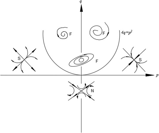
FIGURE 1.
Figure 1 shows an idealized linear phase space diagram with all of the patterns and distribution of limit streamlines that can appear on the object surface: when
Experimental Model and Research Method
Experimental Model
An experimental device is often used to evaluate the performance of axial flow fans. Pressure sensors are installed at the outlet of the collector and the entrance of the fan. A data collector is used to record pressure signals and motor parameters. The hub ratio of the fan is 0.4, the speed is 980–990 rpm, the outer diameter is 1,600 mm, the length of the intake duct is 4,000 mm, and the measuring length is 4,815 mm. We designed and manufactured the forward-swept blades ourselves, with the blade parameters shown in Figure 2 and Table 1. The total height of blade is 480 mm, of which 60% is straight blade, 40% is swept forward blade, and forward swept angle is 20°.
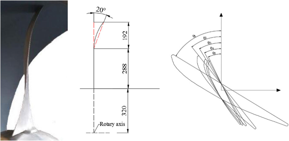
FIGURE 2. Parameters of the forward-swept blade.
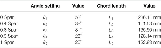
TABLE 1. Specific blade parameter values.
Numerical model
ANSYS computational fluid dynamics X (ANSYS CFX) was used to simulate the whole flow passage at the fan. The physical model was divided into three areas: the inlet and outlet ducts and the experimental fan itself. The blade was meshed using Auto-Grid. An H-block was adopted for the inlet and outlet parts, with an O-block for the blade part, as shown in Figure 3. The quality of the grid is an important factor in the accuracy of the simulation results, and
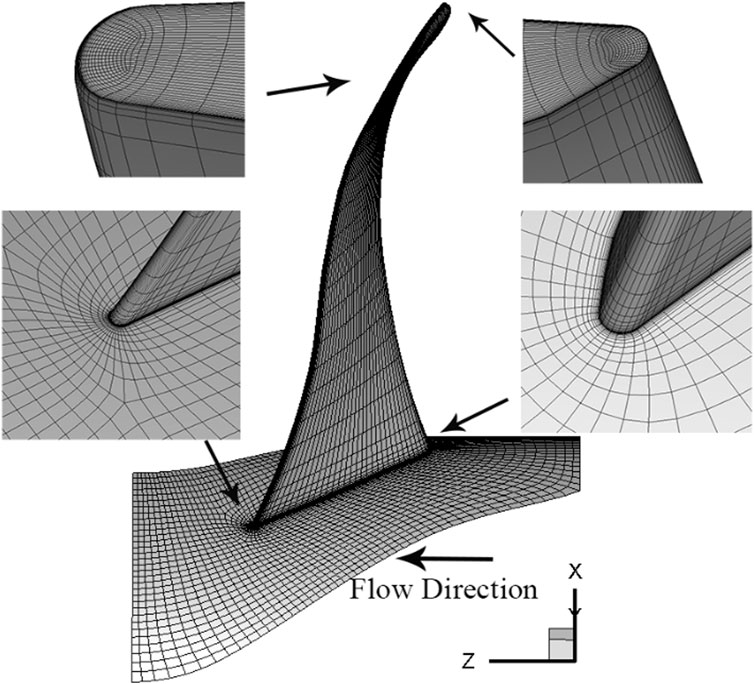
FIGURE 3. Computational mesh of forward-swept fan.
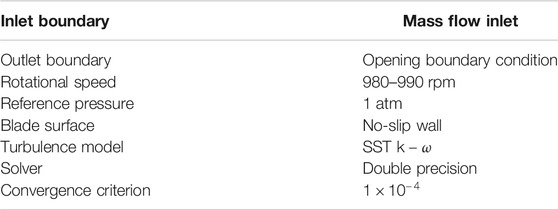
TABLE 2. Boundary conditions and convergence criteria for computation.
To eliminate the influence of the number of grid cells on the numerical results, four different grid resolutions were selected for calculation. The SST
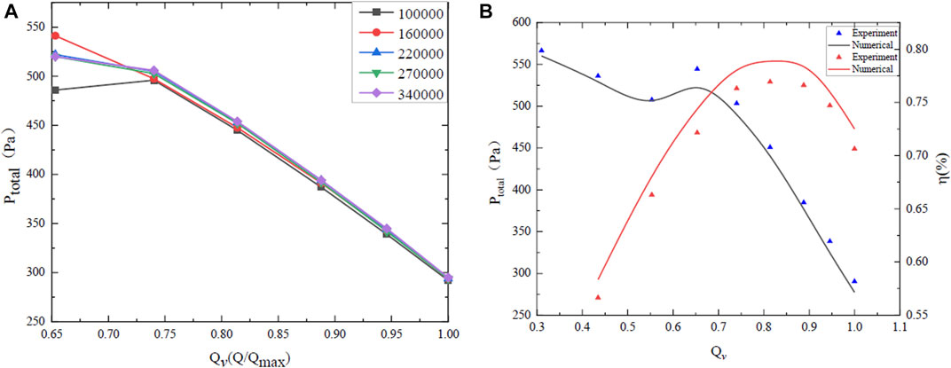
FIGURE 4. Model validation (A) Mesh independent verification (B) Numerical simulation and experimental data.
Results and Analysis
Topological Analysis of Flow Separation
From Figure 1, it can be seen that the singularity type of the phase space diagram formed by the surface streamlines is independent of the time term, but is related to the eigenvalue
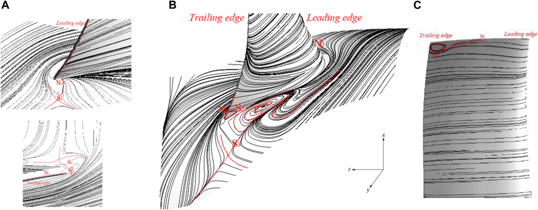
FIGURE 5. Streamline at single channel region in (A) leading edge and trailing edge, (B) hub and blade, and (C) top of blade.
Because of the relative motion between the blade and the flow field, the streamline aligns well with the wall and no flow separation occurs on the pressure surface of the blade. The streamline is significantly deflected by the suction surface of the blade; this is caused by the change of flow direction and the circumferential pressure gradient at the suction surface. According to the separation morphology, the separation starting point lies on the hub and cannot be seen, and closed separation occurs for the passage vortices. The starting point of the separation on the suction surface is a saddle point, and the subsequent separation is a free vortex separation, which is close to open separation. The flow separates at a position 35% along the chord length and enters the mainstream before forming a vortex downstream; coupling of the hub and wall fluid boundary layers also occurs.
The hydrodynamic system in the rotor is nonlinear due to the unsteady working conditions. Many singularities appear on the hub and suction surface, and these influence the detailed fluid motion. Taking the local single passage in the rotor region as an example, the fluid enters from a large distance and no singularity appears on the separation line at the hub. The first group of singularities (saddle nodes) appears at the leading edge of the blade. There is a large corner separation coupling area between the suction surface and the hub, which affects the suction surface of the blade and the streamline at the hub. On the pressure surface, the streamline begins to shift upward from the middle position, and saddle point S2 appears. The limit friction line terminates at the trailing edge of the blade, as shown in Figure 5A. The starting point of separation in this region is saddle point S2, and the separation terminates at tail edge node N2. As they are affected by the corner separation vortices, the larger separation vortices appear at the position where the suction surface streamline deviates, and the separation vortices form focus point F3 on the streamline at the hub.
The separation eddy line comes from two directions: the streamline near the suction leading edge of the blade and saddle point S3 at the hub on the trailing edge of the blade. During the analysis process, saddle point S4 was only found at the trailing edge of the blade and no matching singularity was found, which is inconsistent with the theoretical analysis. By encrypting the streamlines, a separate focus point F4 was found at the junction of the pressure surface and suction surface on the trailing edge of the blade. Finally, the separation at the tip of the blade covers the region from the beginning of saddle point S5 in the middle of the blade to the end of focus point F5 near the trailing edge.
According to the principle of topological invariance, separated saddle points and attachment points (S1–N1) appear near the leading edge of the hub in a single passage near the blade. A saddle–node combination (S2–N2) is formed between saddle point S2 on the trailing edge and node N2 on the trailing edge. A saddle point–focus point pairing (S3–F3) occurs in the mainstream of the suction surface, and finally focus point F4 and saddle point S4 (S4–F4) combine near the root of the trailing edge of the blade. A separation saddle point S5 from the tip of the blade connects with focus point F5 at the trailing edge to form a saddle point–focus point pairing (S5–F5). Through analysis of the topological structure, it is found that the numbers of saddle and node pairs are the same in the single passage region, which is in good agreement with the theory of topological invariance.
Singularity Distribution on Forward-Swept Blade
When the limit streamline is a separation line, the distribution and coordination mode of the singularities on the separation line can be obtained by Taylor expansion. The frictional line equations can be expanded based on Taylor’s formula at the origin of the object surface:
The singularity of the solution to the surface friction line is given by:
In Eq. 10, when
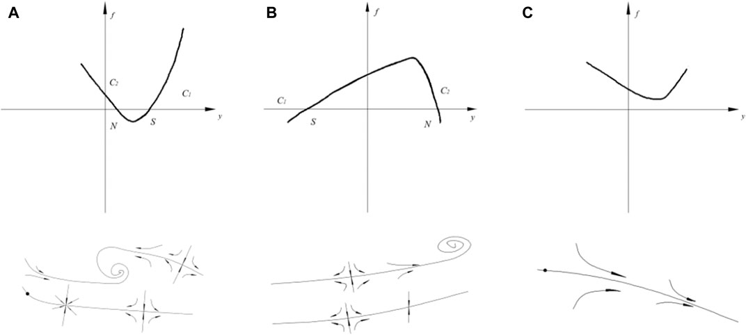
FIGURE 6. Nonlinear solutions and singularity combinations when (A)
As shown in Figure 6A, the separation streamline has two singularities:
where
Flow separation occurs because the boundary layer leaves the blade and enters the mainstream, finally forming a free vortex surface. During the formation and development process, there is a change in the eigenvalues on the suction surface of the blade and hub due to, for example, changes in the wall reverse velocity gradient and the wall separation point. Figure 7 shows the topological structure and reverse flow (blue area) on the hub and blade surface at 0.65 Qv. The first and second groups of singularities start from a saddle point and end at a node point, which is consistent with the combination form of the singularity in Figure 6B. Combined with Figure 7, it can be seen that saddle points S1 and S2 flow from the blue area to the red area, which means that
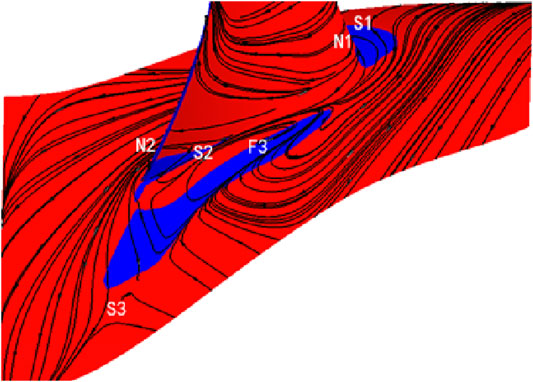
FIGURE 7. Contours of
Generally, the separation line is composed of a saddle point and the focus node. The location and type of the singularity can be quickly defined by the velocity gradient and streamline on the surface, as shown in Figure 8. There are three kinds of
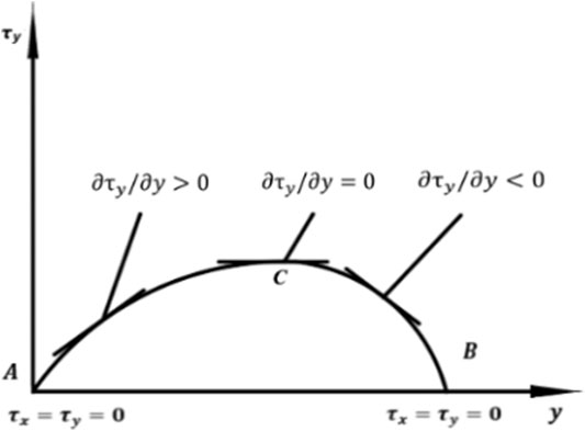
FIGURE 8. Shear stress distribution on the limit streamline.
Spatial Evolution of Separation Vortex Structure
In the steady state, the streamline coincides with the path line. The structure and shape of the separation vortices can gradually be revealed by taking successive cross-sections. Firstly, different planes are selected along the blade height, and the three-dimensional flow field information is obtained by plotting the streamline topology intercepted by each plane. When using the cross-section streamline method to analyze vortex structures away from the wall, the selected surface should be parallel to the surface of study. This paper selects the suction surface and performs a radial translation
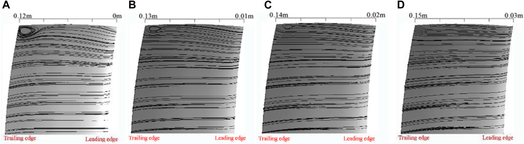
FIGURE 9. Blade streamline topology at (A)
The separation vortex structure on the hub surface can be analyzed by the same method (see Figure 10). On the plane at the hub (0% Span), there is only one shedding vortex at the suction surface, and its core position is 0.23 m away from the fan rotor entrance. With an increase in height (1% Span), two separated vortices grow in the region, located 0.18 and 0.25 m away from the rotor inlet of the fan. When the height reaches 2% Span, the shedding vortices at point B near the suction surface gradually shrink and diffuse into the mainstream. The core of the shedding vortices is at point A, 0.21 m from the rotor inlet, and finally appears at 5% Span; here, the shedding vortices at point B are completely annihilated in the mainstream, leaving only the shedding vortices at point A. The eddy is 0.24 m away from the fan entrance.
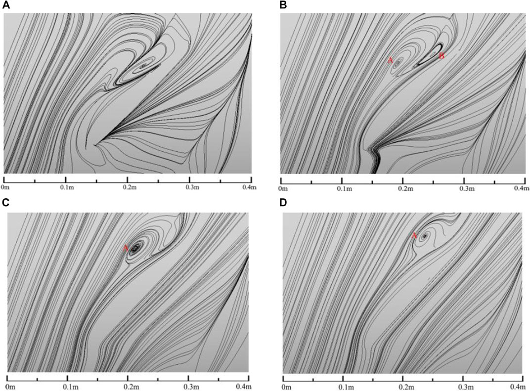
FIGURE 10. Streamline topology at (A) 0% Span, (B) 1% Span, (C) 2% Span, and (D) 5% Span.
Figure 11 shows the streamlines in the impeller region at 0.625
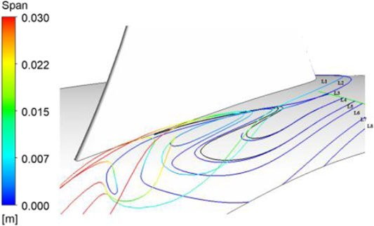
FIGURE 11. Streamlines in the impeller region.
According to Figures 10, 11, the shedding vortices formed on the hub surface disappear with the mainstream, and the positions of the vortex cores in different sections move along the streamline continuously. The shedding vortices break up and diffuse into the mainstream until they dissipate completely. As the flowrate decreases, the influence of the mainstream on the structure of the vortex gradually weakens, and the velocity and location of the vortex breakdown on the hub wall changes, as shown in Figure 12.
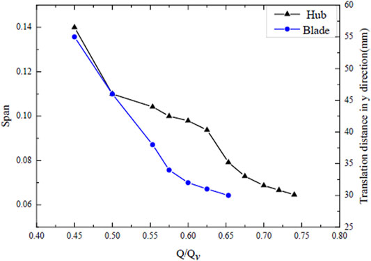
FIGURE 12. Eddy dissipation at different flowrates.
Variation of Separated Vortex Structure With Flow Rate
The topological structure of the rotor is not invariant under changes in flowrate, as shown in Figure 13. When the flowrate is 1 Qv, there are only two groups of singularities in the region (red line). When the flowrate decreases to 0.8 Qv, singularity F3–S3 grows on the hub and S2–N2 appears on the suction surface. When the flowrate is further reduced to 0.625 Qv, separation begins at the blade tip and a new singularity S5–F5 appears. When the flowrate is 0.5 Qv, a new singularity S6–F6 appears on the hub.
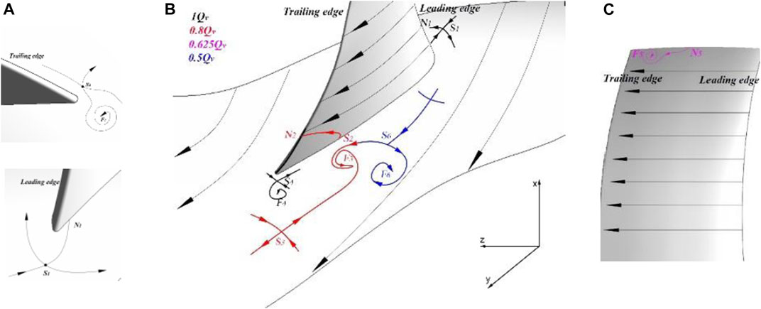
FIGURE 13. Topology under different flowrates.
The passage vortex structure can be inferred from the topological structure and cross-section flow pattern distribution, combined with the spatial streamline distribution, as shown in Figure 14B. Along the flow direction, the fluid forms a horseshoe vortex (HV) near the leading edge. According to Figure 9B, the horseshoe vortex is separated into two parts by the leading edge. The bifurcation of the passage vortex on the pressure surface (HP) rotates clockwise [as shown in Figure 14A, Z/C = 0], and finally converges with the passage vortex to form a single structure. Through local magnification, it can be observed that there is a counterclockwise-rotating vortex near the suction surface of the leading edge, which is the bifurcation of the passage vortex on the suction surface (HS). The passage vortex (PV) rotates clockwise and gradually approaches the suction surface as the flowrate decreases. In the vicinity of the suction surface, the corner vortex (CV) formed by the counter current in the region rotates counterclockwise. The shedding vortex (SV) near the trailing edge is caused by the pressure difference when the pressure surface meets the suction surface fluid. The direction of motion is from the pressure surface to the suction surface, and the rotation direction is counterclockwise. A clockwise-rotating concentrated shedding vortex (CSV) is formed by the boundary layer movement in the corner of the suction surface of the blade top.
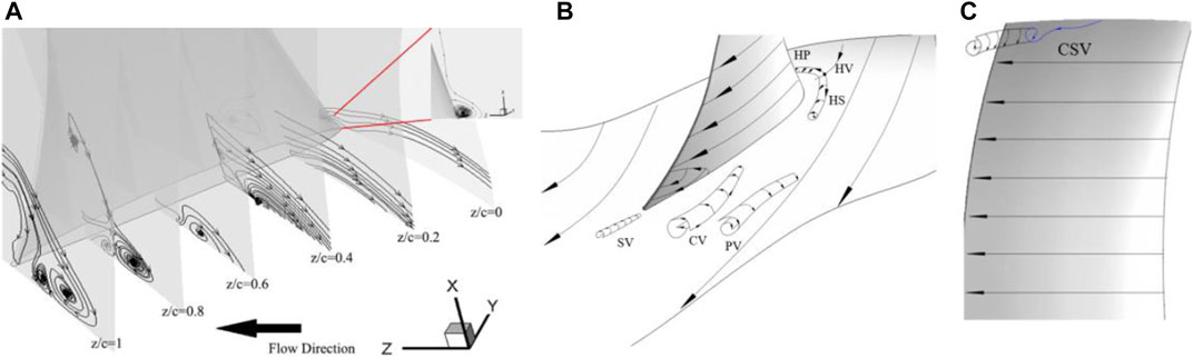
FIGURE 14. Spatial structure of vortex system.
Conclusion
(1) The combinations of different singularities were obtained through a qualitative analysis of the limit friction line on the wall. The method accurately obtains the wake vortices formed by the convergence of the suction surface and pressure surface fluid at the trailing edge of the blade. The flow on the forward-swept blade also follows the principle of topological invariance. The single blade and its adjacent flow passage can be regarded as a closed region. When there is no tip clearance, the Euler characteristic is 0. Through this method, five saddle points, two nodes, and three focus points were found by analyzing the singularities near the runner and the blade.
(2) By taking the Taylor expansion of the governing equation of the limit streamline, the distribution of singular points along the separation line was obtained. Because the change in
(3) The dynamical state of separation vortices on the hub was analyzed using cross-section streamline analysis. As the height increases, the separation vortices break up and are annihilated, and the position of the vortex core moves along the streamline. Changes in flowrate also affect the suction boundary.
(4) With decreasing flowrate, the number of groups of singularities in the region increases, and the combinations of singularities are more abundant. In addition, the section flow pattern method can be used to infer the vortex structure and rotation direction. Numerical simulations show that larger PV and CV are produced, while the CSV and HV are smaller. The HP, PV, and CSV were found to rotate clockwise, whereas the HS, CV, and SV rotate in a counterclockwise direction.
Data Availability Statement
The original contributions presented in the study are included in the article/Supplementary Material, further inquiries can be directed to the corresponding authors.
Author Contributions
YL and ZZ provided experimental ideas and theoretical guidance. PW and SD provided language guidance and writing guidance.
Funding
This work was supported by the National Natural Science Foundation of China (Grant No. 51776217) and the China Scholarship Council (Grant No. 201806425052).
Conflict of Interest
The authors declare that the research was conducted in the absence of any commercial or financial relationships that could be construed as a potential conflict of interest.
Abbreviations
References
Cao, L. (2019). Analysis on Flow Separation Characteristics of Last Stage Blade in Steam Turbine under Small Volume Flow Condition. Therm. Sci. 23, 25. doi:10.2298/tsci180904025c
Chen, L., Liu, X. J., Yang, A. L., and Dai, R. (2013). Flow Performance of Highly Loaded Axial Fan with Bowed Rotor Blades. IOP Conf. Ser. Mater. Sci. Eng. 52, 042005. doi:10.1088/1757-899x/52/4/042005
Dród, A. (2021). Effect of Reynolds Number on Turbulent Boundary Layer Approaching Separation. Exp. Therm. Fluid Sci. (EXP THERM FLUID SCI) 125, 110377. doi:10.1016/j.expthermflusci.2021.110377
Filippov, G. A., and Wang, Z. Q. (1962). The Calculation of Axial Symmetric Flow in a Turbine Stage with Small Ratios of Diameter to Blade Length. Teplienergetika 8, 42.
Gbadebo, S. A., Cumpsty, N. A., and Hynes, T. P. (2005). Three-dimensional Separations in Axial Compressors. J. Turbomach.-Trans. ASME 127, 331–339. doi:10.1115/1.1811093
He, C., Ma, Y. F., Liu, X. H., Sun, D. K., and Sun, X. F. (2018). Aerodynamic Instabilities of Swept Airfoil Design in Transonic Axial-Flow Compressors. AIAA J. 56, 1. doi:10.2514/1.j056053
Jongwook, J., Medic, G., and Sharma, O. (2016). “Large-eddy Simulation Investigation of Impact of Roughness on Flow in a Low-Pressure Turbine,” ASME Turbo Expo. Turbomachinery Technical Conference & Exposition.
Karyakin, O. M., Nalivaiko, A. G., Ustinov, M. V., and Flaxman, J. S. (2018). Separation Control on the wing by Jet Actuators. AIP Conf. Proc. 1959, 050014.
Kaya, M. N., Kose, F., Ingham, D., Ma, L., and Pourkashanian, M. (2018). Aerodynamic Performance of a Horizontal axis Wind Turbine with Forward and Backward Swept Blades. J. Wind Eng. Ind. Aerodynamics 176, 166–173. doi:10.1016/j.jweia.2018.03.023
Lighthill, M. J. (1963). ‘‘Attachment and Separation in Three-Dimensional Flows,’’ in Laminar Boundary Layers. Editor L. Rosenhead (Oxford, UK: Oxford Univ. Press), 72–82.
Luo, D., Huang, D., Sun, X., Chen, X., and Zheng, Z. (2017). A Computational Study on the Performance Improvement of Low-Speed Axial Flow Fans with Microplates. Jafm 10, 1537–1546. doi:10.29252/jafm.73.245.27492
Maskell, E. C. (1955). “Flow Separation in Three Dimensions,” Royal Aircraft Establishment. Report No.: Aero 2565.
Mohammed, K. P., and Raj, D. P. (1977). Investigations on Axial Flow Fan Impellers with Forward Swept Blades. ASME J. Fluid Eng. 99, 543–547. doi:10.1115/1.3448839
Pogorelov, A., Meinke, M., and Schröder, W. (2016). Effects of Tip-gap Width on the Flow Field in an Axial Fan. Int. J. Heat Fluid Flow 61, 466–481. doi:10.1016/j.ijheatfluidflow.2016.06.009
Surana, A., Grunberg, O., and Haller, G. (2006). Exact Theory of Three-Dimensional Flow Separation. Part 1. Steady Separation. J. Fluid Mech. 564, 57. doi:10.1017/s0022112006001200
Vad, J., Halász, G., and Benedek, T. (2015). Efficiency Gain of Low-Speed Axial Flow Rotors Due to Forward Sweep. Proc. Inst. Mech. Eng. A: J. Power Energ. 229, 16–23. doi:10.1177/0957650914552817
Wang, Z. Q., Lai, S. K., and Xu, W. Y. (1981). “Aerodynamic Calculation of Turbine Stator Cascades with Curvilinear Leaned Blades and Some Experimental Results”. Proceedings of the 5th ISABE. Bangalore
Wang, Z. Q. (1999). Three-dimensional Theory and Design Method of Bowed Twisted Blade and its Application to Turbomachines. van Karman Institute for Fluid Dynamics, Vol. 2, D1–D41.
Wennerstrom, A. J. (1990). Highly Loaded Axial Flow Compressors: History and Current Developments. J. Turbomach. 112, 567–578. doi:10.1115/1.2927695
Wennerstrom, A. J., and Puterbaugh, S. L. (1984). A Three-Dimensional Model for the Prediction of Shock Losses in Compressor Blade Rows. J. Eng. Gas Turbine Power 106, 295–299. doi:10.1115/1.3239562
Ye, Z., Zhao, H. Y., Yang, Y., Li, C., and Gao, W. (2013). Effect of Inlet Prewhirl on Flow Field of Axial Flow Fan. Amr 732-733, 571–576. doi:10.4028/www.scientific.net/amr.732-733.571
Zhang, H., Wang, S., and Wang, Z. (2007). Variation of Vortex Structure in a Compressor cascade at Different Incidences. J. Propulsion Power 23, 221–226. doi:10.2514/1.17245
Zhang, H. X. (1994). Bifurcation of Vortex Motion along its axis. Acta Aerodynamica Sinica 3, 243. (in Chinese).
Zhang, H. X. (1997). Crossflow Topology of Three-Dimensional Separated Flows and Vortex Motion. Acta Aerodynamica Sinica 1, 1. (in Chinese).
Zhang, H. X., and Deng, X. (1992). Analytic Studies for Three-Dimensional Steady Separated Flows and Vortex Motion. Acta Aerodynamica Sinica 1, 8. (in Chinese).
Keywords: flow separation, forward-swept blade, topological analysis, vortex structure, limit streamline
Citation: Liang D, Li Y, Zhou Z, Wiśniewski P and Dykas S (2021) Structure and Topology Analysis of Separated Vortex in Forward-Swept Blade. Front. Energy Res. 9:693596. doi: 10.3389/fenrg.2021.693596
Received: 11 April 2021; Accepted: 06 May 2021;
Published: 20 May 2021.
Edited by:
Lin Teng, Fuzhou University, ChinaReviewed by:
Hongbing Ding, Tianjin University, ChinaBin Liu, Shijiazhuang Tiedao University, China
Xu Han, North China Electric Power University, China
Copyright © 2021 Liang, Li, Zhou, Wiśniewski and Dykas. This is an open-access article distributed under the terms of the Creative Commons Attribution License (CC BY). The use, distribution or reproduction in other forums is permitted, provided the original author(s) and the copyright owner(s) are credited and that the original publication in this journal is cited, in accordance with accepted academic practice. No use, distribution or reproduction is permitted which does not comply with these terms.
*Correspondence: Z. Zhou, enpud3RAMTYzLmNvbQ==; P. Wiśniewski, cGlvdHIud2lzbmlld3NraUBwb2xzbC5wbA==