 Zhenao Sun
 Fanglin Zhu
- College of Information Science and Engineering, Northeastern University, Shenyang, China
Virtual synchronous generator (VSG) is one of the inverter control methods which can provide extra virtual moment of inertia and achieve frequency support by mimicking the output characteristics of a rotating synchronous generator (RSG), which makes VSG particularly suitable for multi-access point applications, or called the multi-VSG system. However, frequency fluctuations may often occur in the case of power variation. In terms of this issue, this study presents the small-signal state-space model of VSG and analyzes the cause of frequency fluctuation, first. And then, a novel VSG control method is proposed for frequency fluctuation attenuation. The proposed method is especially fit for the parallel multi-VSG system because it does not take grid angular frequency into computation so that it can get rid of the ill effect introduced through PLL. The damping power item is reconstrued with a new means to judge whether the system is in a steady state or not. At the same time, the parametric design method of the proposed method is also figured out. Finally, the simulation experiments are performed, and the results verify that the proposed method performs better than the conventional one in terms of dynamic response and power-sharing among the multi-VSG system.
Introduction
In recent years, with the development of distributed energy resources (DERs) and microgrids (DG), more and more power electronic devices have been added to the grid. However, huge challenges, such as the problem of lack of inertia, damping, and rotational reserve capacity, have emerged with a large number of power electronic equipment. In order to solve these issues, virtual synchronous generator (VSG) has been employed to the control system of distributed energy power generation equipment (Hafner et al., 2011; Mo et al., 2017; Wang et al., 2020), which can make the equipment have frequency and voltage regulation characteristics similar to conventional synchronous generators.
The basic theory of VSG has been explained in the studies by D’Arco and Suul (2014)and Driesen and Visscher (2008), and the mathematical model and implementation are investigated under the title of synchronverter (Zhong and Weiss, 2011; Zhong et al., 2014). VSG strategy has been introduced in frequency, voltage, and active and reactive power flow control (Wang et al., 2020). Consequently, VSG control strategy has been applied to different devices and occasions, such as energy storage (Ma et al., 2017), doubly fed induction generators (Hwang et al., 2017), high-voltage direct current transmission (Aouini et al., 2016), and direct current (DC) generators (Wu et al., 2017).
Unfortunately, in the VSG control system, when the distributed power supply fluctuated drastically, the power and frequency outputs of the system are prone to oscillations. In order to effectively eliminate the effects of fluctuations on the system, various control methods have been proposed (Wu et al., 2016; Li et al., 2017a; Alsiraji and El-Shatshat, 2017; Shi et al., 2018; Wang et al., 2018a). In the study by Wu et al. (2016), by adjusting the damping coefficient, moment of inertia, and other related parameters of the VSG, the output characteristics can be directly changed to achieve suppression of power and frequency fluctuations. A bang–bang control method with adaptive moment of inertia has been proposed (Shi et al., 2018) by selecting various rotational inertia under different operating conditions. In order to design the parameters more conveniently, a small-signal model has been introduced in the study byWang et al. (2018a) to determine the best damping coefficient and moment of inertia in the system. Moreover, a model that aims at the minimum transient response time has been established, and the influence of the frequency amplitude and rate of change has been considered (Li et al., 2017a). However, the damping coefficient of the above control method was set to zero under specific operating conditions, which led to a limited range of applications. Therefore, an optimal damping ratio control strategy has been proposed in the study by Alsiraji and El-Shatshat (2017) to improve the transient frequency, power response, and stability of the VSG system. Nevertheless, this method cannot maintain the best damping ratio during the entire operation of the system.
However, the transient condition tolerance of VSG units is much less than that of a real synchronous generator (Alipoor et al., 2015). To solve the issue of frequency fluctuation, at present, more and more scholars are devoted to the research of parameter adaptation. Damping and moment of inertia designed in the study by Li et al. (2017b) follow the law that damping is reduced in the interval of ∆ω (dω/dt) > 0 and remains at D0in in other times, while the moment of inertia setting rule is opposite. However, the optimal relationship and extreme values between virtual inertia and damping coefficient have not been studied in depth. Besides, in the initial state after the disturbance, virtual inertia and the damping coefficient are small, which greatly limit the transient stability. The study by Alipoor et al. (2018) does not include a theoretical analysis of the influence of the damping coefficient. In some specific cases, this control strategy is difficult to implement. Although the study by Wang et al. (2018b) contains a comprehensive theoretical analysis of damping and moment of inertia and optimal parameter selection, there are only two virtual inertia values in this control strategy, which reduces the operating performance of the controller during critical disturbances.
The methods mentioned above, which improve the oscillation of the VSG system frequency and active power, were mainly realized by changing the system parameters. Traditional methods have limited the application of control strategies that change parameters. At the same time, these methods all aimed at the operation of a single VSG, failing to reflect the power and frequency changes of multiple VSGs operating in parallel. According to the analysis above, this study proposes a new control strategy to suppress the attenuation of the frequency and active power of multiple VSGs.
In summary, the control method of the parallel multi-VSG system should be different from that of the single VSG system. However, few of the existing methods can improve the transient stability according to the characteristics of the multi-VSG system. Some certain special means should be taken to enhance the transient performance of the former system. A frequency fluctuation attenuation method is needed for the parallel multi-VSG system. Thus, this study aimed to investigate the parallel operation of VSGs with a damping correction term added to the swing equation. The addition of the extra term intends to achieve better oscillation damping in a multi-VSG environment. The load changing transients and eigenvalue analysis were employed to validate the transient and small-signal stability of the system with the proposed strategy.
The article is arranged as follows. Section Single VSG Connected to the Infinite Grid presents the model of a single VSG connected to the infinite grid. Section The Course of Frequency Fluctuation analyzes the course of frequency fluctuation in the parallel multi-VSG system. Section The Proposed Control Method for the Parallel Multi-VSG System proposes a novel control method for frequency fluctuation attenuation in the parallel multi-VSG system. Section Simulation Results exhibits and analyzes the simulation results to verify that the proposed method performs better than the conventional one. At last, Section Conclusion summarizes the article conclusions.
Single Virtual Synchronous Generator Connected to the Infinite Grid
Two Control Loops of a Virtual Synchronous Generator
Figure 1. illustrates the model of a single VSG connected to the infinite grid, with the DC side of the VSG ignored. Figure 1 shows two main control loops: active power control loop (APCL) and reactive power control loop (RPCL). The P-ω droop, Q-V droop, and swing equation are contented. Their detailed block diagrams are shown in Figure 2.
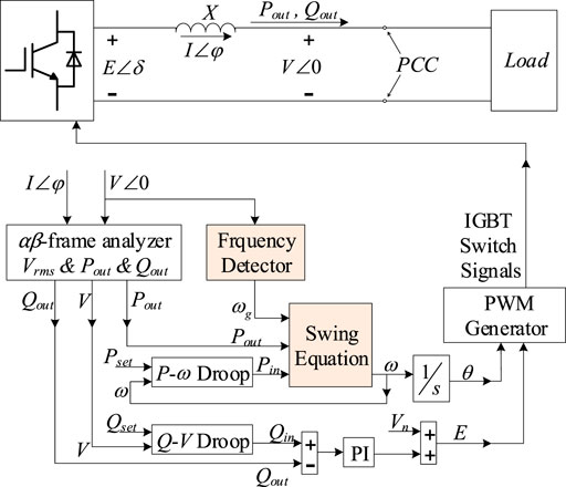
FIGURE 1. Single VSG connected to infinite grid.
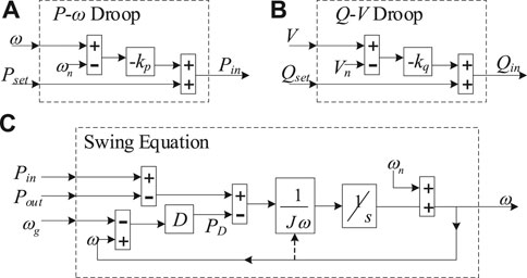
FIGURE 2. Block diagram of (A)P-ω Droop, (B)Q-V Droop, and (C) swing equation.
In Figure 2, kp and kq are the droop coefficients of each loop correspondingly, J is the virtual rotational inertia, D is the damping factor, ωn is the nominal value of the grid angular frequency, and ω0 is the grid angular frequency on the steady-state operating point.
Equations 1–4 describe the APCL:
and Eqs 5,6 describe the RPCL (Hafner et al., 2011; Mo et al., 2017):
Figure 3 is the vector diagram of Figure 1 (ignore R).
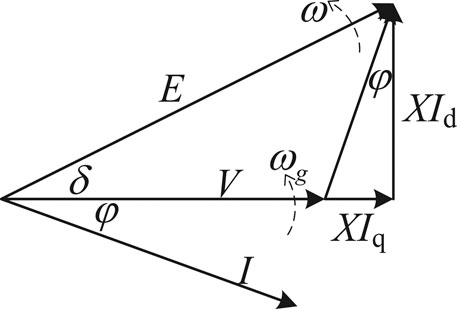
FIGURE 3. Vector diagram of a VSG.
Figure 3 reveals the role of δ, formulated as Eqs 7–9.
It is noticed that APCL is key to VSG control because the main characteristic of the VSG is to introduce a virtual rotational inertia J in order to mimic the dynamic performance of an RSG, and APCL is more complex than RPCL.
Decoupling of the Two Control Loops
The small-signal model of Eqs 7,8 can be expressed in a matrix as Eq. 9 (Zhong and Weiss, 2011):
It seems like the two control loops are coupling with each other, but we can do some approximations to decouple them and reveal the decoupling conditions.
In engineering practice, the short-circuit radio ISC/In is usually designed more than 10, formulated as (Ma et al., 2017)
Substituting Eq. 6 into Eq. 10, we get Eq. 11:
In this case, δ is usually a tiny angle. For example, a 10-kW inverter connects to a 380/220 V three-phase grid with a 4-mH filter inductor: sin δ = 0.0862 < 0.1, then δ = 0.0863 and tan δ = 0.865; they are approximately equal, and cos δ = 0.9963 ≈ 1. So, in VSG control, we consider
In another word,
Substituting Eqs 12, 13 into Eq. 10 and writing the small-signal model of Eq. 9, we get Eq. 14:
Substituting Eqs 1, 2 into Eq. 3 and deducing its small-signal model, we have Eq. 17:
Similarly, substituting Eqs 5,13 into Eq. 6 and deducing its small-signal model, we have Eq. 16:
Then, the small-signal model of Figures 1, 2 can be illustrated in Figure 4:
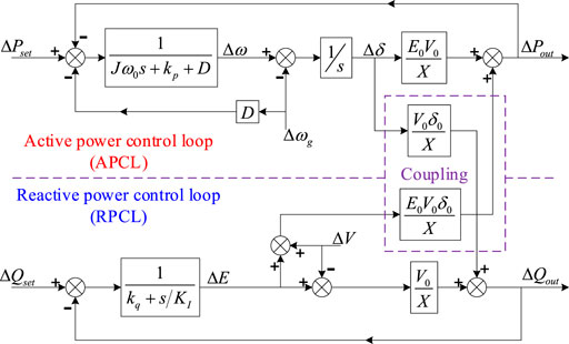
FIGURE 4. Small-signal control model.
For ΔPout(s), Δδ is the input signal and ΔE and ΔV are the disturbance input signals. If we can prove the loop gain from Δδ to ΔPout(s) is much larger than that from ΔE+ΔV to ΔPout(s), we can overlook the coupling item from RPCL to APCL, and thus consider that the APCL is decoupled from RPCL.
Overlooking the coupling items, define the forward path gain of APCL as Ffp(s):
Then the transfer functions between ΔPout (s) and Δδ (s) or E (s)+V (s) can be formulated as (Alsiraji and El-Shatshat, 2017; Alipoor et al., 2015), separately.
Since |F1(s)|/|F2(s)| >> 1, compared to F1(s), F2(s) can be neglected; in another word, APCL is decoupled from RPCL. In the similar way, RPCL can also be decoupled from APCL approximately.
So, we can analyze the two control loops separately, in the condition where short-circuit ratio is more than 10, which is always satisfied in the inverter design.
The Course of Frequency Fluctuation
Intrinsic Oscillation Mode
The VSG has a better transient stability because it emulates the swing equation of an RSG to provide virtual rotational inertia and extra frequency support to the grid. However, the emulation of swing equation of a conventional synchronous generator (SG) also introduces an oscillatory mode, which makes VSG-controlled inverters subjected to intrinsic low-frequency oscillation.
Define K as the transient synchronizing power coefficient in Eq. 22:
Arrange Eqs 1–3, 9, 20 in the state-space form shown in Eq. 21:
In Eq. 23, the output vector y, the state vector x, the input vector u, the state matrix A, and the input matrix B are as Eq. 22:
Normally, the system operates in the underdamping state, and the eigenvalues of A can be deduced as Eq. 23:
Therefore, the undamped natural frequency ωun and the damping ratio ζ of the intrinsic oscillation of the VSG can be represented as Eq. 24.
From Eq. 24, we can conclude that the undamped natural frequency ωun will decrease as the virtual rotational inertia J increases, which is not influenced by the damping factor D. At the same time, larger J will result in smaller ζ, which may make the system more prone to oscillation. However, D can also influence ζ positively. Those relations can also be confirmed from the eigenvalue loci plot in Figure 5. The parameters involved are presented in Table 1. In Figure 5, J and D vary in proportion.
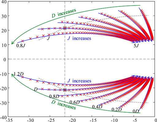
FIGURE 5. Eigenvalue loci when J or D varies in the underdamping state.
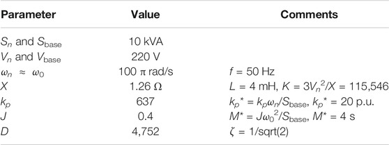
TABLE 1. Same parameters involved.
Frequency Fluctuation in the Parallel Multi-VSG System
The VSG mimics the output characteristics of the RSG, so the frequency fluctuation of the parallel multi-VSG system can also be compared to the state of the multi-RSG system. In the multi-RSG system, in order to keep in sync, the parallel RSG continuously adjusts the angular frequency of their respective rotors, which might cause a frequency fluctuation of the grid. In this situation, it is even more difficult to keep the RSGs in sync, resulting in continuous frequency fluctuation.
Similar situation can be seen in the parallel multi-VSG system. Because of the particularity of power electronic equipment, the controller of a VSG cannot obtain the grid angular frequency directly. A frequency detector, such as a phase-locked loop (PLL), is a must in the conventional VSG control method.
However, the response rate of digital PLL is much slower than that of mechanical PLL, which makes the frequency fluctuation in the parallel multi-VSG system even worse. Thus, a novel PLL-free VSG control method is needed for the frequency fluctuation attenuation in the parallel multi-VSG system.
The Proposed Control Method for the Parallel Multi-VSG System
Novel Constitution of Damping Power Item PD
The damping power item PD is the only item that needs a frequency detector in the basic VSG control method. In order to get rid of the PLL, we must reconstruct the item PD without using a frequency detector. So, we will first analyze the mechanism of original PD in the basic VSG control, and then come up with a new way to obtain PD.
From the study by Zhong et al. (2014), we can notice that PD remains at 0 in a steady state and makes differences only in transient. The basic method takes the comparison of ω and ωg as a way to assess whether the system is operating in a steady-state condition or not. If ω = ωg, the system is operating in a steady-state condition and PD should remain at 0. If ω
So that, if we want to obtain PD in a novel way without using frequency detector, we must find a new way to assess the steady-state condition. In the system, Pin and Pout share a similar relationship with ω and ωg. If Pin = Pout, the system is operating in the steady-state condition; if not, transient.
Thus, we can conclude that PD should satisfy the following requirements:
(1) It should contain a factor, for example, Pin − Pout, to estimate whether the system is operating in the steady-state condition.
(2) It must turn to and remain at zero in the steady-state condition so that it will not affect the steady operating point of droop relation in the steady-state condition.
(3) Even if it introduces extra poles, the dominant poles of the new system should be closed to or coincident with the original two poles.
(4) It must contain a DΔω item in its small-signal model so that the state matrix A and its eigenvalues will not change. Since Pin contains a kp·ω item and it will become a kp·Δω item in its small-signal model, we do not need to constitute it dedicatedly and only need to adjust its coefficient.
To meet the four abovementioned requirements, we propose a novel way to obtain PD, formulated as
where H is the output power error amplification factor and KD is the self-integral coefficient.
The first requirement is satisfied obviously. The second requirement is satisfied through the integral item, which will force PD to turn to and remain at 0 in the condition of KD > 0. The third and fourth requirements need proper parameter design, which will be detailed in the next subsection.
Figure 6 shows the block diagram of the swing equation of the proposed method using the novel way to obtain PD. Comparing it with the original one shown in Figure 2C, it is noticed that the grid frequency does not participate in the computation; thus, it can avoid the ill effect of frequency detector.
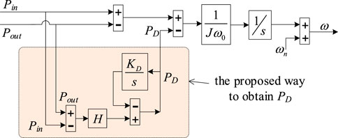
FIGURE 6. Block diagram of the swing equation of the proposed method.
Parameter Design of the Proposed Control Method
There are two parameters in Eq. 25, H and KD, whose values need to be decided, and we can adjust these two parameters to meet the third and the fourth requirements.
To meet the third requirement, we should first deduce the eigenvalues of the proposed system. Arrange Eqs 1, 3, 4, 9, 25 in the state-space form as shown in Eq. 21, and use a superscript to distinguish the corresponding vector or matrix in Eq. 22; then we can get Eq. 26.
In Eq. 11, most parameters in A′ are deterministic, except for H and KD, which correspond to ωun and ζ. We need to find a combination of H and KD, which will make the dominant poles of the new system closed to or to be coincident with the original ones, as shown in Eq. 23 and Figure 5.
In order to get the eigenvalue expressions of A′, we plot the eigenvalue loci with varying H and KD to find a fitful combination, as shown in Figure 7. The eigenvalue loci are shown in Figure 6. With two parameters to be decided, this is something like “trial and error.” But later in this section, we will prove that there is only one parameter that needs to be decided, and the root locus alike method can be used in this situation.
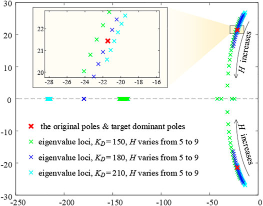
FIGURE 7. Eigenvalue loci when H or KD varies.
It is noticed that on the condition that KD = 180 and H = 7.4, the dominant poles of the new system are almost coincident with the original poles, and the other pole is assigned much farther to the left than the dominant, which satisfies the third requirement.
What is more; substituting H = 7.4 into A′, we notice that D = H·kp and A′11 = A11, which means the fourth requirement is also satisfied. Thus, we know that the conjugate eigenvalues are the dominant poles of A′. If A′11 = A11, then the dominant poles of A′ will be the same as the original poles of A. So, we can use the equation A′11 = A11 or D = H·kp to obtain H directly, leaving KD itself to be determined by the eigenvalue loci.
With only one single variable parameter to be determined, we can use a method similar to the root locus method to choose a suitable value on eigenvalue loci. The very single variable parameter of the mentioned method is KD, not the open loop gain in the root locus method. And this method can be named as root locus alike method.
There are two parameters in the proposed method to be decided, H and KD. H can be calculated directly, and KD is picked up by the root locus alike method. No complicated formula derivation is involved in the parameter design approach, so this method can simplify the parameter design process.
Simulation Results
Simulation I: Single Virtual Synchronous Generator to Infinite Grid
In the grid-connected mode, the steady-state frequency is determined by the power grid. Assuming it is an infinite grid, the steady-state frequency would never change. The simulation topology is shown in Figure 8, and the control parameters are shown in Table 1.
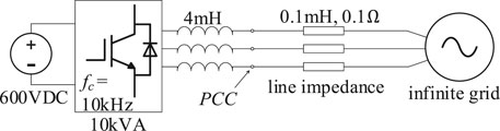
FIGURE 8. Simulation topology of a VSG connected to the infinite grid.
In Situation I, the VSG could affect the frequency of PCC only in the transient state when the power reference Pset changes. Thus, we set Pset at 5kW at first; after the system reaches a steady state, Pset is then increased to 8kW. Four different control methods are applied in the same situation to compare the active power oscillation and angular frequency fluctuation. The simulation results are shown in Figure 9.
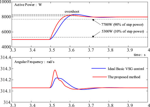
FIGURE 9. Simulation results I: different VSG methods in the grid-connected mode.
In Figure 9, the ideal basic VSG control method is not the “conventional scheme” but the “conventional scheme with an ideal PLL.” An ideal PLL can only be obtained in simulation but cannot be realized in practice. A nonideal PLL in practice usually has an adverse effect on dynamic performance of the system. So, the simulation of “conventional scheme with an ideal PLL” is obviously better than that of “conventional scheme” on dynamic performance.
In the proposed method, the ωun and ζ are also set at the same values as the ideal basic VSG control to mimic its dynamic properties.
The dynamic response of the ideal basic VSG control method is much better than that of the conventional scheme. The former can be considered as the target of the VSG control method. From Figure 9, we notice that the dynamic response of the proposed method is very close to that of the ideal basic method, and some indicators are even better. Thus, we can conclude that the proposed method is better than the conventional scheme in this situation.
Simulation II: Multi-VSGs With the Same Control Method
We use two parallel VSGs to simulate the parallel multi-VSG system. The simulation topology is shown in Figure 10.
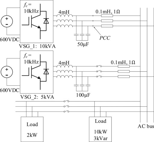
FIGURE 10. Simulation topology of two VSGs sharing power in islanding.
VSG_1 is a 10-kVA inverter, and its main parameters are shown in Table 1. VSG_2 is a 5-kVA inverter, and its main parameters are shown in Table 2. Although the actual values of their most corresponding parameters are different, the per-unit values are almost all the same.
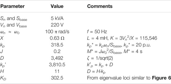
TABLE 2. Parameters of the 5 kVA inverter.
At first, VSG_1 is set to output 8 kW active power, which is 80% of its rated power. The load is set to consume 10 kW active power. On 3 s, VSG_2 prepares to connect to the grid, and connects to the grid after about 0.1 s; its output active power is set to 4 kW, which is also 80% of its rated power. Then, another 2 kW load is connected to the grid on about 5.5 s and the load steps to 12 kW in total. At last, the target power of VSG_1 is increased to 10 kW on about 8 s, and the target power of VSG_2 is maintained at 4 kW.
We did the simulation experiments twice. In the first simulation, both the VSGs are applied as the VSG ideal basic control method with an ideal PLL. In the second simulation, both the VSGs are applied as the proposed control method. In simulation, we can use an ideal PLL to get rid of the ill effect introduced through the actual PLL; however, the ideal PLL can never be realized in actual engineering, which makes the first simulation results much better than the real system. So, if the second simulation results are similar to those of the first one, it can certify that the proposed control method is better than the ideal basic control method, for the proposed one does not contain a PLL originally.
The simulation results are shown in Figure 11.
(1) The proposed control method has a similar dynamic response and steady operating point to the ideal basic control method.
(2) On about 5.5 s, the load is increased from 10 to 12 kW. At that very moment, no matter which control method is launched, each parallel VSG increases its output equally, which is related to the equal line impedance. Then, different control methods make differences to adjust the active power and achieve power-sharing. Finally, in the ideal basic control method and the proposed one, ΔP1 ≈ 2·ΔP2, which also means that the output power ratios to the rated power of the two VSGs are almost the same; thus, power-sharing is achieved well when the load is changed.
(3) On about 8 s, the load and the target power of VSG_2 remain unchanged, and the target power of VSG_1 turns to 10 kW. We can notice that the output angular frequencies of both VSGs increase and the VSG_1 increases. Because the angular frequency of VSG_2 is forced to increase by VSG_1, a few seconds later, the output power of VSG_1 does not reach 10 kW and the output power of VSG_2 decreases. This is the result of P-ω droop and power-sharing.
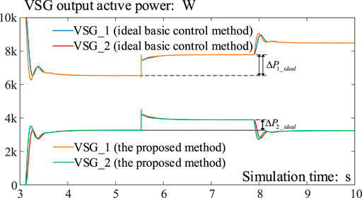
FIGURE 11. Simulation results II: multi-VSGs with the same control method.
We can conclude from this simulation that the proposed method performs similarly to the ideal VSG control method. We can reasonably infer that the proposed method performs better than the conventional method in the parallel multi-VSG system.
Simulation III: The Cooperation Between the Proposed Method and the Ideal Basic One
The most important feature of VSG is that it can achieve power-sharing without using communication; thus, in this subsection, we use two parallel VSG-controlled inverters with diffident rated powers to demonstrate the power-sharing effect. VSG_1 (10 kV A) applies the ideal basic VSG control method, and VSG_2 (5 kV A) applies the proposed method. The topology of the simulation is shown in Figure 12. The control parameters of the two VSGs are listed in Tables 1,2.
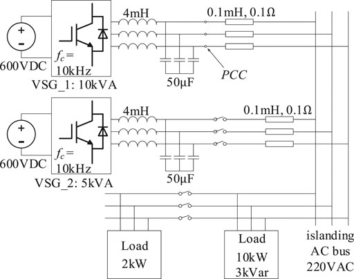
FIGURE 12. Simulation topology of two VSGs sharing power in islanding.
At first, VSG_1 is set to output 8kW active power, which is 80% of its rated power. The load is set to consume 10 kW active power. On 3 s, VSG_2 starts to prepare to connect to the grid and completes connecting after about 0.1 s; its output active power is set to 4 kW, which is also 80% of its rated power. Then another 2 kW load is connected to the grid on about 5.5 s, making the load step to 12 kW in total. At last, the power reference of VSG_1 steps up to 10 kW on about 8 s, and the power reference of VSG_2 remains at 4 kW. The simulation results are shown in Figure 13.
(1) On about 5.5 s, the load steps up. The proposed approach finally achieves power-sharing with the basic VSG control method because in Figure 10, ΔP1 ≈ 2·ΔP2 and ΔP1/Sbase_1 ≈ ΔP2/Sbase_2.
(2) Similar results can be seen after 8 s; when the power reference of VSG_1 steps up, the angular frequency changes a little, which results that VSG_2 shares some of the power increase.
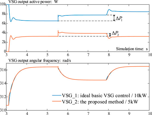
FIGURE 13. Simulation results III: the proposed method and the ideal basic method.
Simulation III verifies that the proposed approach has a good power-sharing ability without using frequency detector.
In practice, the infinite grid is rare; most VSGs are connected to a non-infinite grid formed mainly by RSGs. Since the ideal basic VSG control method is the imitation of RSG, this simulation can also be treated as a VSG connected to an RSG or practical non-infinite grid.
Conclusion
This study aimed to investigate the parallel operation of VSGs with a damping correction term added to the swing equation. The addition of the extra term intends to achieve better oscillation damping in a multi-VSG environment. The load changing transients and eigenvalue analysis were employed to validate the transient and small-signal stability of the system with the proposed strategy.
In this article, a novel VSG control method is proposed for frequency fluctuation attenuation. The proposed method does not take grid angular frequency into computation, so that it can get rid of the ill effect introduced through PLL, which makes it especially fit for the parallel multi-VSG system. The damping power item is reconstrued with a new means to judge whether the system is in the steady state or not. The parametric design method is also figured out. At last, the simulation results to verify that the proposed method performs better than the conventional one.
Data Availability Statement
The raw data supporting the conclusion of this article will be made available by the authors, without undue reservation.
Author Contributions
ZS has done the main theory research work. FZ has done some of the simulation work. XC has done the work of article writing.
Conflict of Interest
The authors declare that the research was conducted in the absence of any commercial or financial relationships that could be construed as a potential conflict of interest.
References
Alipoor, J., Miura, Y., and Ise, T. (2015). Power System Stabilization Using Virtual Synchronous Generator with Alternating Moment of Inertia. IEEE J. Emerg. Sel. Top. Power Electron. 3 (2), 451–458. doi:10.1109/jestpe.2014.2362530
Alipoor, J., Miura, Y., and Ise, T. (2018). Stability Assessment and Optimization Methods for Microgrid with Multiple VSG Units. IEEE Trans. Smart Grid 9 (2), 1462–1471. doi:10.1109/tsg.2016.2592508
Alsiraji, H. A., and El-Shatshat, R. (2017). “Comprehensive Assessment of Virtual Synchronous Machine-Based Voltage Source Converter Controllers”, IET Generation. Transm. Distribution, 11, 1762–1769.
Aouini, R., Marinescu, B., Ben Kilani, K., and Elleuch, M. (2016). Synchronverter-Based Emulation and Control of HVDC Transmission. IEEE Trans. Power Syst. 31 (1), 278–286. doi:10.1109/tpwrs.2015.2389822
D'Arco, S., and Suul, J. A. (2014). Equivalence of Virtual Synchronous Machines and Frequency-Droops for Converter-Based MicroGrids. IEEE Trans. Smart Grid 5 (1), 394–395. doi:10.1109/tsg.2013.2288000
Driesen, J., and Visscher, K. (2008). Virtual Synchronous Generators. in Proc. IEEE Power Energy Soc. Gen. Meeting-Conversion and Delivery of Electrical Energy in the 21st Century, 1–3.
Hafner, M., Finken, T., Felden, M., and Hameyer, K. (2011). Automated Virtual Prototyping of Permanent Magnet Synchronous Machines for HEVs. IEEE Trans. Magn. 47 (5), 1018–1021. doi:10.1109/tmag.2010.2091675
Hwang, M., Muljadi, E., Jang, G., and Kang, Y. C. (2017). Disturbance-adaptive Short-Term Frequency Support of a DFIG Associated with the Variable Gain Based on the ROCOF and Rotor Speed. IEEE Trans. Power Syst. 32 (3), 1873–1881. doi:10.1109/tpwrs.2016.2592535
Li, D., Zhu, Q., Lin, S., and Bian, X. Y. (2017). A Self-Adaptive Inertia and Damping Combination Control of VSG to Support Frequency Stability. IEEE Trans. Energ. Convers. 32 (1), 397–398. doi:10.1109/tec.2016.2623982
Li, D., Zhu, Q. S., and Bian, X. Y. (2017). A Self-Adaptive Inertia and Damping Combination Control of VSG to Support Frequency Stability. IEEE Trans. Energ. Convers. 32 (1), 397–398. doi:10.1109/tec.2016.2623982Li
Ma, Y., Cao, W., Yang, L., Wang, F. F., and Tolbert, L. M. (2017). Virtual Synchronous Generator Control of Full Converter Wind Turbines with Short-Term Energy Storage. IEEE Trans. Ind. Electron. 64 (11), 8821–8831. doi:10.1109/tie.2017.2694347
Mo, O., D'Arco, S., and Suul, J. A. (2017). Evaluation of Virtual Synchronous Machines with Dynamic or Quasi-Stationary Machine Models. IEEE Trans. Ind. Electron. 64 (7), 5952–5962. doi:10.1109/tie.2016.2638810
Shi, K., Ye, H., Song, W., and Zhou, G. (2018). Virtual Inertia Control Strategy in Microgrid Based on Virtual Synchronous Generator Technology. IEEE Access 6, 27949–27957. doi:10.1109/access.2018.2839737
Wang, F., Zhang, L., Feng, X., and Guo, H. (2018). An Adaptive Control Strategy for Virtual Synchronous Generator. IEEE Trans. Ind. Applicat. 54 (5), 5124–5133. doi:10.1109/tia.2018.2859384
Wang, F., Zhang, L., Feng, X., and Guo, H. (2018). An Adaptive Control Strategy for Virtual Synchronous Generator. IEEE Trans. Ind. Appl. 54 (5), 5124–5133.
Wang, S., Jing, L., Zhao, Y., Wickramasinghe, H. R., Wu, X., and Konstantinou, G. (2020). Operation of Unified Power Flow Controller as Virtual Synchronous Generator. IEEE Access 8, 162569–162580. doi:10.1109/access.2020.3021388
Wu, H., Ruan, X., Yang, D., Chen, X., Zhao, W., Lv, Z., et al. (2016). Small-signal Modeling and Parameters Design for Virtual Synchronous Generators. IEEE Trans. Ind. Electron. 63 (7), 4292–4303. doi:10.1109/tie.2016.2543181
Wu, W., Chen, Y., Luo, A., Zhou, L., Zhou, X., Yang, L., et al. (2017). A Virtual Inertia Control Strategy for DC Microgrids Analogized with Virtual Synchronous Machines. IEEE Trans. Ind. Electron. 64 (7), 6005–6016. doi:10.1109/tie.2016.2645898
Zhong, Q.-C., Nguyen, P., Ma, Z., and Sheng, W. (2014). Self-synchronized Synchronverters: Inverters without a Dedicated Synchronization Unit. IEEE Trans. Power Electron. 29 (2), 617–630. doi:10.1109/tpel.2013.2294425
Keywords: parallel multi-VSG system, frequency fluctuation, grid angular frequency, damping power item, dynamic performance
Citation: Sun Z, Zhu F and Cao X (2021) Study on a Frequency Fluctuation Attenuation Method for the Parallel Multi-VSG System. Front. Energy Res. 9:693878. doi: 10.3389/fenrg.2021.693878
Received: 12 April 2021; Accepted: 01 June 2021;
Published: 22 June 2021.
Edited by:
Yonghao Gui, Aalborg University, DenmarkReviewed by:
Kenneth E. Okedu, National University of Science and Technology (Muscat), OmanKrishnakumar R. Vasudevan, Universiti Tenaga Nasional, Malaysia
Copyright © 2021 Sun, Zhu and Cao. This is an open-access article distributed under the terms of the Creative Commons Attribution License (CC BY). The use, distribution or reproduction in other forums is permitted, provided the original author(s) and the copyright owner(s) are credited and that the original publication in this journal is cited, in accordance with accepted academic practice. No use, distribution or reproduction is permitted which does not comply with these terms.
*Correspondence: Zhenao Sun, c3VuemhlbmFvQG1haWwubmV1LmVkdS5jbg==