 Luyao Xie
 Xin Guo1
 Chun Wei
- 1College of Information Engineering, Zhejiang University of Technology, Hangzhou, China
- 2Zhijiang College of Zhejiang University of Technology, Shaoxin, China
- 3State Grid Gansu Electric Power Company, Wuwei Power Supply Company, Wuwei, China
In a multiterminal DC (MTDC) system with a large number of different types of energy storage devices, the AC terminals and the energy storage devices need to cooperate to maintain the stability of the DC bus voltage. Due to the difference in the dynamic and static power capability of each energy storage unit, the dynamic and static power should be distributed separately. To solve the above problems, an adaptive droop control strategy based on the dynamic and static power decoupling is proposed in this paper. The impact of the virtual impedance values on the dynamic and static power flows between the DC voltage regulating terminals operating with the RC droop method is analyzed. Through optimized virtual capacitance and adaptive virtual resistance, the dynamic power and static power can be distributed according to the PCS capacity and the available charge–discharge battery capacity, respectively. In addition, a simple secondary control method is adopted to compensate the static deviation of the DC bus voltage. Finally, a six-terminal MTDC system model is established in Matlab/Simulink, and the simulation results verify the feasibility and effectiveness of the proposed control strategy.
Introduction
A multiterminal DC (MTDC) system has become a research hotspot because of its advantages such as easy access of energy storage devices, strong power regulation ability, easy realization of power flow reversal, flexible transmission mode, and reliable power supply (Zheng et al., 2020a; Zheng et al., 2020b). Along with the deep-going of the research, the access terminal of an MTDC system is more and more complex, such as AC side with three-phase unbalanced load, renewable energy resources, and weak AC grid (Davari and Mohamed, 2013; Huang et al., 2020; Yang et al., 2020; Ma et al., 2021). Specifically, with the increasing proportion of renewable energy resources and application demand of weak AC power grid, it is necessary to configure a large number of different types of energy storage devices in an MTDC system to maintain the power balance of the system. In such an MTDC system with high proportion of energy storage, the system is no longer dominated by the AC terminals. Therefore, the AC terminals and the energy storage devices need to cooperate to maintain the instantaneous power balance of the system, so as to maintain the stability of the DC bus voltage.
For an MTDC system with large capacity energy storage, it is necessary to establish a multilayer cooperative control structure. The multilayer cooperative control structure must be suitable for an MTDC system with any number of AC terminals or DC terminals to ensure the voltage stability of the DC bus. At present, the typical cooperative control strategies are the master–slave control, DC voltage margin control, and DC voltage droop control (Chen et al., 2010; Beerten et al., 2014; Wang et al., 2015; Wei et al., 2021). Among them, the multilayer cooperative control structure based on the DC voltage drop control is more competitive because of its lower communication requirements and better expansibility (Gavriluta et al., 2013; Gavriluta et al., 2015; Zhang et al., 2020). In the work of Gavriluta et al. (2013) and Gavriluta et al. (2015), an improved primary control based on the droop control and dc bus signaling is proposed, which provides modularity and extendibility to the system. Zhang et al. (2020) proposed a novel droop control with power margin correction factor and the corresponding system-level operation strategy, which improves the operation states and control parameters of the MTDC system. However, the droop control is a kind of upper control method, and its output command needs to be executed by power conversion system (PCS) of each regulating terminal. Due to the differences in circuit structures and control methods, the performance of different regulating terminals may deviate greatly even executing the same droop command. Therefore, when establishing converter control methods for different types of terminals, it is necessary to ensure that they have consistent droop command execution characteristics. Subsequently, any type of terminal can be equivalent to a unified regulating terminal model, which improves the extendibility of the droop control.
The distribution of the total regulated power is another problem worthy of further study. The traditional droop control defines the droop coefficient as the ratio of the maximum power margin to the maximum voltage margin (Haileselassie and Uhlen, 2012; Rouzbehi et al., 2015; Abdel-Khalik et al., 2016; Cao et al., 2018; Kirakosyan et al., 2018). The disadvantage of this method is that the droop coefficient is a constant, which is not suitable for changing operation conditions. To achieve better performance, some schemes for adapting the droop coefficients are proposed (Chen et al., 2017; Wang et al., 2018; Li et al., 2020). The work of Dragicevic et al. (2013) and Gavriluta et al. (2014) shows that the droop coefficient can be changed adaptively according to the SOC of energy storage units, so as to ensure the balance of SOC in different energy storage units. The SOC adaptive drop control is excellent for the MTDC system with the same rated capacity of different energy storage units. However, unreasonable situation that the energy storage units with the same SOC but huge capacity difference bear the same static power will occur if the rated capacity of energy storage units is inconstant. In such an MTDC system, the available charge–discharge capacities may be considered as adaptive parameters to maintain the SOC balance in different energy storage units.
Due to the differences in rated capacity of PCSs, the dynamic power capability of different regulating terminals is also different. Furthermore, the dynamic and static power capability of each regulating terminal may also be different. Therefore, the disturbance power of an MTDC system should be decoupled into dynamic and static components and properly distributed. To solve the problem, the power distribution method of hybrid energy storage devices in the DC microgrid can be used for reference. In the work of Xu et al., 2017; Zhang and Wei Li, 2017; and Shi et al., 2019, the hybrid energy storage is composed of a battery and super-capacitor. The battery adopts virtual resistance droop control to bear a low-frequency power component, while the super-capacitor adopts virtual capacitance droop control to bear a high-frequency power component, which realizes the dynamic and static power decoupling. In the work of Chen et al., 2019, the disturbance power is divided into different frequency bands in the form of a virtual resistor and a virtual capacitor in series, which are shared by different types of energy storage devices.
For an MTDC system with high-capacity energy storage, this paper proposes an improved RC droop control with adaptive virtual resistance, which improves the dynamic and static power distribution performance and the system extendibility. The contributions of this paper are as follows:
1) Any DC or AC terminal can be equivalent to a unified controllable DC voltage source model regulated by upper voltage command. The unified model can be extended to the MTDC system with any number of AC and DC hybrid regulating terminals.
2) The upper RC droop control strategy generates voltage regulation commands of each unified voltage source model, separates the system disturbance power into dynamic and static components, and distributes them reasonably among regulation terminals.
3) The static power is distributed according to the available charge–discharge capacity of the battery at each DC regulating terminal by adaptive adjustment of virtual resistance, which achieves the consistency of the charging and discharging process at each storage unit.
System Structure and Modeling
The modular multilevel converter (MMC) is one of the popular topologies in the MTDC system. Figure 1 shows the structure diagram of the six-terminal MTDC system in which two terminals are connected to the weak AC grids through the AC/DC MMC. One terminal is connected to the strong AC grid through the AC/DC MMC, another terminal is connected to the island load through the AC/DC MMC, and the rest of the two terminals are connected to the energy storage devices through the DC/DC MMC.
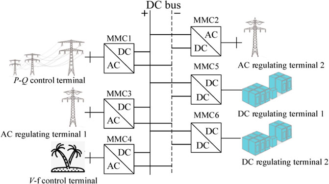
FIGURE 1. Structure diagram of the six-terminal MTDC system.
When the system operates normally, it is assumed that MMC1 works in the PQ control mode and receives the power grid dispatching instructions and MMC4 works in the V–F control mode and supplies power to the island area; other terminals work in the DC voltage droop control mode to maintain the stability of the DC bus voltage.
Modeling of AC/DC Converter
The topology of the AC/DC MMC circuit is shown in Figure 2. Each bridge arm is composed of n sub-modules (SM) with the same structure and arm inductance Larm. The upper and lower bridge arms constitute a phase unit. The mathematical model is shown in Eq. 1 in a dq synchronous rotating frame,
where L and RL are inductance and resistance at the AC side of MMC, respectively; id and iq are the d-axis and q-axis components of the MMC AC side current, respectively; CO is the equivalent DC-link capacitance; RC is the equivalent safe discharge resistor of the system;
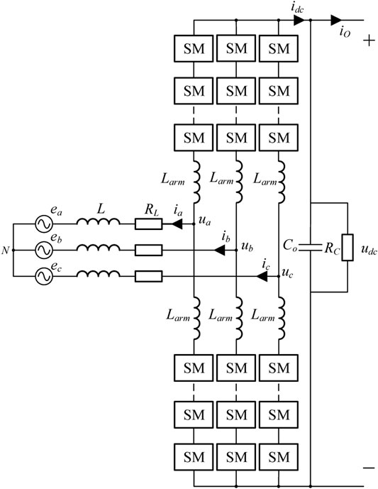
FIGURE 2. Topology of the AC/DC MMC circuit.
In this paper, grid voltage orientation is adopted, so eq = 0. If converter loss is ignored, the active and reactive power of the converter can be expressed as follows:
From (Eq. 2), the governing equation of the dc voltage control loop can be obtained, as shown in (Eq. 3). From (Eq. 1), the dq axis components present a coupling relationship. To realize the independent control of id and iq, it needs to be decoupled. The PI regulator is used in the inner current loop, and the control equation is shown in (Eq. 4). The control block diagram is shown in Figure 3.
where kvp and kvi are the proportion coefficient and integral coefficient of the outer udc-Q loop, respectively, and kip and kii are the proportional coefficient and integral coefficient of the inner current loop, respectively.
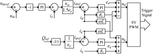
FIGURE 3. Control block diagram of the AC/DC MMC.
In order to obtain the dynamic characteristics of the voltage loop, the response speed of the id current loop needs to be analyzed first. We can get the following results by substituting (Eq. 4) into (Eq. 1):
Laplace transformation of Eq. 5 gives
From Eq. 6, it is easy to find that the id current loop can be considered as a first-order loop when
Similarly, the dynamic characteristics of the outer voltage loop can be derived. By substituting Eq. 3 into Eq. 2, we can get
Laplace transformation of Eq. 8 gives
The udc loop can also be considered as a first-order loop when
Modeling of DC/DC Converter
The topology of the DC/DC MMC is shown in Figure 4, which is composed of n buck-boost converters in series. Since the duty cycle of each unit is almost the same, the MMC can be equivalent to a buck-boost circuit, as shown in Figure 5. The mathematical model is shown by the following equation:
where
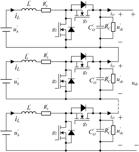
FIGURE 4. Topology of the DC/DC MMC.
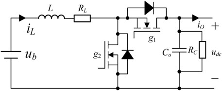
FIGURE 5. Equivalent circuit of the DC/DC MMC.
The control equations of the outer voltage loop and inner current loop can be obtained from Eq. 11 as shown in Eq. 12, where kvp and kvi are the proportion and integral coefficients of the voltage outer loop, respectively; kip and kii are the proportional and integral coefficients of the inner current loop, respectively. The control block diagram is shown in Figure 6.
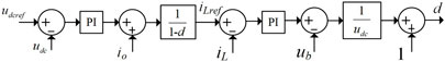
FIGURE 6. Control block diagram of the DC/DC MMC.
The dynamic performance of the voltage loop is also important to DC voltage droop control. To obtain the dynamic characteristics of the voltage loop, the inner current loop also needs to be analyzed. We can get the following results by substituting Eq. 12 into Eq. 11:
Laplace transformation of Eq. 13 gives
It is also a first-order loop when
To obtain the response time of the outer voltage loop, we can substitute Eq. 12 into Eq. 11,
Laplace transformation of Eq. 16 gives
The udc loop can also be considered as a first-order loop when
Unified Controllable Voltage Source Model
According to Eqs 7, 10, 15, 18, the response time of the AC/DC MMC and DC/DC MMC is consistent. Assuming that the response time of the inner current loop is designed to be far smaller than that of the outer voltage loop (τv > 5τi), the influence of the inner current loop can be ignored. The control block diagram of each regulating terminal can be simplified as a first-order delay loop, which is shown in Figure 7A. Its structure can be unified as a controllable voltage source model, as shown in Figure 7B. In order to ensure that all the regulating terminals have consistent droop command response characteristics, the time constant τv of all the terminals should be consistent.
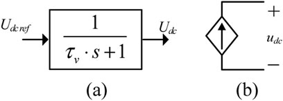
FIGURE 7. Simplified control block diagram and controllable voltage source model. (A) Block diagram of DC voltage control. (B) Controllable voltage source model.
Multilayer Collaborative Control
In this paper, a multilayer collaborative control strategy with different time scales is used, and the control block diagram is shown in Figure 8. According to different time scales, the coordinated control mainly includes the converter control, primary control, and secondary control. The primary control uses the DC voltage to output current (udc-io) droop control, which distributes the disturbance power among the regulating terminals. The secondary control is used to compensate the static DC voltage deviation caused by the primary control. Both the converter control and the primary control are implemented by the local controller at each regulating terminal, which has good real-time response performance. The secondary control relies on the narrow bandwidth communication channels between the central controller and each regulating terminal. The converter control has been introduced in detail in the previous section, and the details of the primary control and the secondary control will be provided below. The block diagram of multilayer collaborative control is shown in Figure 8. The objectives of different control layers are given in Table 1.
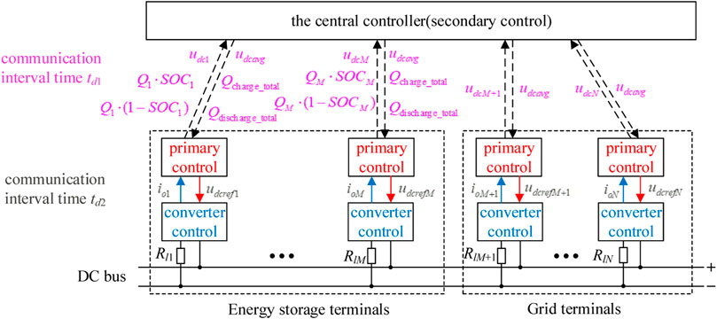
FIGURE 8. Block diagram of multilayer collaborative control.
TABLE 1. Objectives of different control layers.
In Figure 8, there are M energy storage terminals and N-M grid terminals. ioi is the output current of terminal i, udci is the actual output voltage of terminal i, udcavg is the average output voltage of all the terminals, udcrefi is the DC voltage reference value of the terminal i,
The Primary Control
The equivalent two-port circuit network of the traditional droop control is a series connection of a DC source and a virtual resistor, and its resistance value is equal to the droop coefficient. In this paper, an equivalent impedance model of DC source in series with a parallel virtual resistor–capacitor unit is used, as shown in Figure 9. Taking the discharge process as an example, its volt–ampere characteristics are given as follows:
where udcnom is the rated voltage of the DC bus, Ri is the virtual resistance, Ci is the virtual capacitance, Rli is the line resistance, and ubus is the actual voltage of the DC bus.
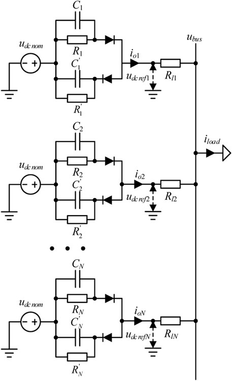
FIGURE 9. Equivalent impedance model of the MTDC system.
The current distribution relationship between converters can be obtained from Eq. 19,
where iRi and ici are the low-frequency and high-frequency parts of the output current of each equivalent impedance.
In the moment of power disturbance, because the capacitance is equivalent to the short circuit, the capacitance determines the dynamic current distribution of each unit. In steady state, because the capacitance is equivalent to the open circuit, the resistance determines the static current distribution of each unit. In this way, the dynamic and static decoupling separation of disturbance power can be realized, and it is distributed according to the design parameters of virtual RC. At the same time, the time constant of the primary control is the product of virtual RC. Since the virtual resistance is generally much larger than the line resistance, the output voltage of each converter is approximately equal to the DC bus voltage.
The Secondary Control
It can be obtained from Eq. 19 that the steady-state DC bus voltage will have static error. To eliminate the static error, a secondary compensation can be added to the reference voltage, and the system impedance model is changed as shown in Figure 10. As a result, the V–I characteristic is changed as follows:
where kp and ki are the proportional and integral coefficients of the secondary control, respectively. Eq. 21 can be simplified as follows:
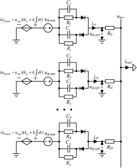
FIGURE 10. Equivalent impedance model of the MTDC system with secondary control.
When kp = 0, it can be seen from Eq. 22 that the secondary control is equivalent to adding a high-pass filter to virtual RC voltage drop. When the time constant of the secondary control is much larger than that of the primary control, the system still distributes power according to the RC characteristics in a short time after the power disturbance occurs, but the voltage drop generated by the RC characteristics will be slowly filtered by the high-pass filter. At this point, the time constant of the system stability is mainly determined by the secondary control, and the time constant can be obtained as follows:
Parameter Design
First, the response time constants of each control layer need to be designed according to the system performance requirements. The multilayer collaborative control strategy needs to meet the condition of
Then, the equivalent resistance Req of the MTDC system can be determined by the total maximum regulating current Imax and the maximum allowable DC voltage deviation
Req is equal to the parallel connection of the equivalent resistance of all energy storage terminals RDC_eq and the equivalent resistance of all grid terminals RAC_eq.
Ri_DC is the virtual resistance of the energy storage terminal i, which can be calculated by Eq. 26. To maintain the consistency of charging and discharging proceeding of each energy storage terminal, the virtual resistance Ri_DC during charging and discharging needs to be designed separately, and the value should change adaptively according to the chargeable capacity and dischargeable capacity. Ri_AC is the virtual resistance of the AC grid terminal i, which can be calculated by Eq. 28. Ri_AC is designed according to the maximum static power capability of each AC grid terminal PACi_max, which is determined by the rated power of the converter and the static power limitation of the AC line.
The virtual capacitance of each terminal is given as follows:
where pi_max is the maximum dynamic power of each regulating terminal. pi_max of the energy storage terminal is determined by the rated power of the DC/DC MMC and the maximum allowable dynamic power of the battery, and pi_max of the AC terminal is determined by the rated power of the AC/DC MMC and the dynamic power limitation of the AC line. Ceq is the equivalent virtual capacitance of the whole system, which satisfies the following relationship:
Finally, the parameters of each control layer can be calculated. According to
According to Eqs 24, 25, 30, when the system performance parameters are determined, Req, Ceq, RDC_eq, and RAC_eq are all constant values. Therefore, the adaptive droop control only changes the resistance distribution among the energy storage terminals but makes no changes to the system parameters. As a result, the total system performance, including the system stability, does not change as the adaptive strategy is performed. Furthermore, the derivative value of the virtual resistance Ri_DC in Eq. 26 is zero in an ideal charging and discharging process without considering the power loss. It proves that the virtual resistance of each energy storage terminal Ri_DC is also constant in an ideal situation. For practical application, a precise SOC estimation model considering battery power loss and other nonlinear parameters can be adopted, and Ri_DC becomes a time-varying variable. By using the adaptive strategy proposed in this paper, precise Ri_DC can be obtained and better static power distribution performance can be achieved.
Simulation Results
In order to verify the effectiveness of the proposed control strategy, a six-terminal MTDC system with high-capacity energy storage is built in Matlab/Simulink as shown in Figure 1. Among the six terminals, MMC1 and MMC4 can be equivalent to active power disturbance sources, and other terminals share the task of the DC bus voltage stability control. The control structures of AC converters and bidirectional energy storage converters are built as shown in Figures 3, 6, respectively. The system parameters of the simulation model are given in Table 2.
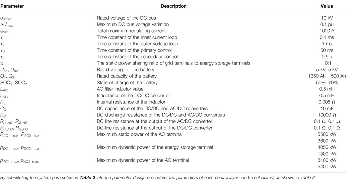
TABLE 2. System parameters.
To verify the advantages of the proposed control strategy in the dynamic and static power distribution performance, this paper selects the traditional droop control strategy for the simulation and comparative analysis. The impedance model of the traditional droop control strategy does not contain virtual capacitance, and virtual resistance parameters are still selected according to Table 3.
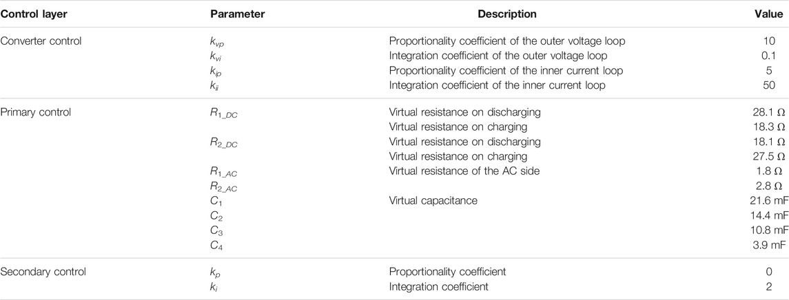
TABLE 3. Parameters of each control layer.
In the charging state, the active power disturbance source changes from 1540 to 2310 kW at 3 s. The simulation results of the proposed method are shown in Figure 11, and the simulation results of the traditional droop control are shown in Figure 12.
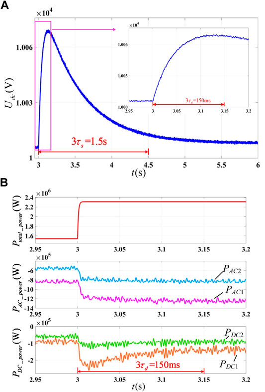
FIGURE 11. Simulation results of the proposed strategy when energy storage terminals on charging: (A) DC bus voltage and (B) output power.
FIGURE 12. Simulation results of the traditional drop control strategy when energy storage terminals on charging: (A) DC bus voltage and (B) output power.
No matter which method is adopted, the DC voltage recovery time after power disturbance is determined by the slowest secondary control time constant
The advantages of the proposed control strategy in dynamic and static power distributions are as follows:
1) The control strategy proposed in this paper provides an additional inertia for the system, which is helpful for the system stability. It can be seen from Figure 11B that the rise time of the DC bus voltage is about three times of
2) The proposed control strategy has better dynamic power distribution performance. Using the proposed control strategy, as shown in Figure 11B, the disturbance power is decoupled to the dynamic and static power and distributed respectively. The dynamic power is distributed as follows:
To illustrate the advantages of the static power distribution of the proposed adaptive scheme, this paper selects two commonly used power distribution methods for comparative analysis: the nonadaptive scheme based on the rated capacity of PCSs and the adaptive scheme based on the SOC of energy storage units. The parameters of the MTDC system are still performed according to Table 2 and Table 3, but the parameters of the energy storage units are changed to those shown in Table 4. The discharge conditions are selected as an example for comparative analysis. In order to prevent overdischarge of the battery, it is assumed that the battery will exit when the SOC is lower than 10%. The current of the exit unit will be shared by other energy storage units.
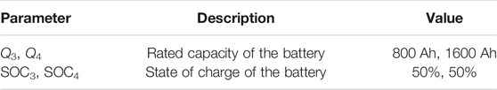
TABLE 4. Parameters of the energy storage units.
As shown in Figures 13–15, the adaptive drop control strategy proposed in this paper has some better characteristics in static power distribution:
1) The control strategy proposed in this paper can enhance the system backup power capacity. Under this control, the changing rate of the SOC at each DC regulating terminal is the same, the two discharge curves coincides, and the two energy storage units exit at the same time due to overdischarge. When other strategies are adopted, one of the energy storage units exits in advance due to overdischarge, resulting in the decline of the dynamic adjustable power capability of the system.
2) When the proposed strategy is adopted, the static power distribution is more reasonable. As shown in Figure 15B, the output current of the two energy storage units remains unchanged, and regulating terminal 4 with large dischargeable capacity bears a large discharge current, which is more reasonable. It can be seen from Figure 14B that when the SOC-based adaptive scheme is adopted, the discharge current of each DC regulation terminal will change with time. At the initial moment, although the initial dischargeable capacity of Q4 is twice than that of Q3, due to the same SOC, the current of the two energy storage units is the same, which is obviously unreasonable.
3) Under the control of the proposed strategy, the communication speed requirement between the central controller and each regulating terminal is lower. Comparing Figures 14, 15, it can be seen that the current distribution ratio and virtual resistance of the SOC-based adaptive scheme change during the discharge process, while these parameters are almost constant under the control of the proposed scheme. All the adaptive schemes rely on the state information sent by the central controller to update the virtual resistance value. Due to the change in the virtual resistance, the requirement of communication speed of the SOC-based adaptive scheme is obviously higher than that of the proposed scheme.
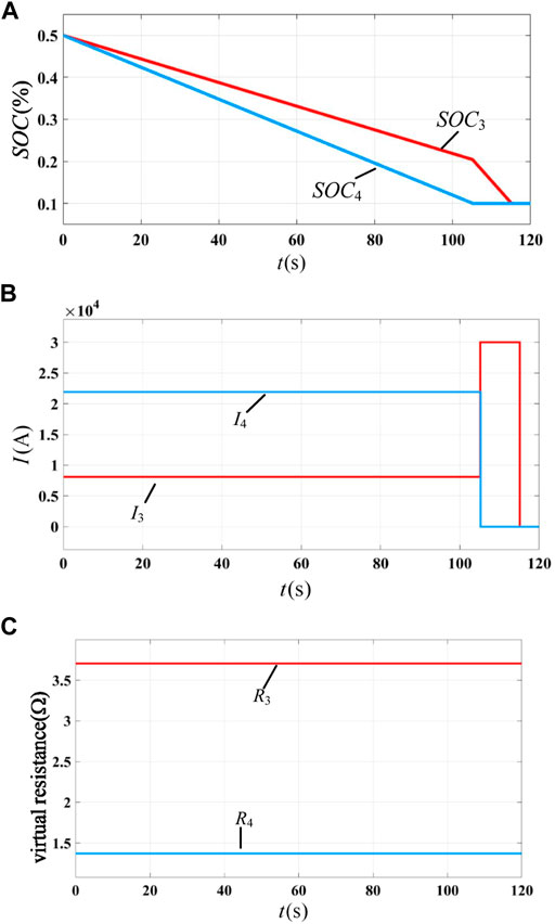
FIGURE 13. Discharge process of storage units with PCS rated capacity based on the nonadaptive scheme: (A) SOC of each energy storage unit, (B) static current of each energy storage unit, and (C) virtual resistance of each energy storage unit.
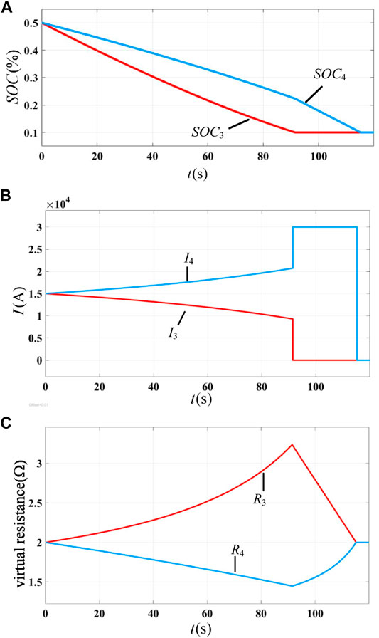
FIGURE 14. Discharge process of storage units with the SOC-based adaptive scheme: (A) SOC of each energy storage unit, (B) static current of each energy storage unit, and (C) virtual resistance of each energy storage unit.
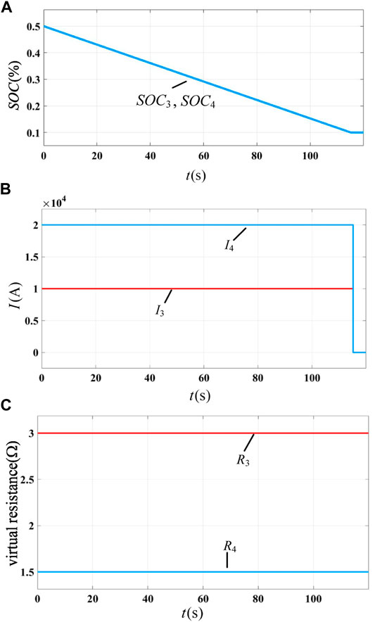
FIGURE 15. Discharge process of storage units with the avaliable-capacity-based adaptive scheme: (A) SOC of each energy storage unit, (B) static current of each energy storage unit, and (C) virtual resistance of each energy storage unit.
In the section Multilayer Collaborative Control, it has been analyzed that the communication interval time td2 is almost negligible, and the transmission interval time td1 between the primary control and the secondary control may play a significant role in the system performance. td1 mainly affects the update speed of the average DC bus voltage in the secondary control. The recovery performance of the DC bus voltage deviation can be used to evaluate its impact on the system performance. The simulation results are shown in Figure 16. It can be seen that when td1 is less than
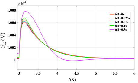
FIGURE 16. Influence of td1 on the DC bus voltage recovery performance.
Conclusion
For an MTDC system with high-capacity energy storage, this paper proposes a multiterminal cooperative DC bus voltage control strategy. The conclusions are summarized as follows:
1) All regulating terminals are equivalent to a controllable voltage source with two delay links, which eliminates the difference between different regulating terminals and realizes the unified upper control interface.
2) Virtual RC drop is used as the primary control to realize the decoupling of the dynamic and static power. By reasonably configuring the virtual impedance, each regulating terminal can bear the power according to its own dynamic and static power capability.
3) The virtual resistance of droop control directly affects the static power distribution of the system. Through adaptive virtual resistance control, the static power can be distributed according to the charge–discharge status and the battery capacity of each energy storage terminal. Under the control of this method, the system has larger backup power capacity, better static power distribution performance, and lower communication speed requirements.
4) The adaptive droop control does not change the system parameters including Req and Ceq, while adjusting the virtual resistance of each energy storage unit. Therefore, the adaptive droop control does not affect the overall performance of the system. This feature makes the control strategy simpler in system parameter optimization and stability design.
5) The control strategy can be divided into three layers: converter control, primary control, and secondary control. The parameter design method of each control layer is given in detail. In addition, when the communication interval time between the central controller and each regulating terminal is less than
Data Availability Statement
The original contributions presented in the study are included in the article/Supplementary Material, and further inquiries can be directed to the corresponding author.
Author Contributions
LX: conceptualization and methodology. XG: writing—original draft. CW: supervision and writing—review and editing. YZ: resources. YC: validation. CL: resources. YX: data curation. EZ: conceptualization and resources.
Funding
This work was supported, in part, by the National Natural Science Foundation of China (Grant No. 51807179) and the Fundamental Commonwealth Research Projects of Zhejiang Province, China (Grant Nos. LGG20E070004 and LGG21E070002).
Conflict of Interest
CL, YX, and EZ were employed by State Grid Gansu Electric Power Company.
The remaining authors declare that the research was conducted in the absence of any commercial or financial relationships that could be construed as a potential conflict of interest.
Publisher’s Note
All claims expressed in this article are solely those of the authors and do not necessarily represent those of their affiliated organizations, or those of the publisher, the editors, and the reviewers. Any product that may be evaluated in this article, or claim that may be made by its manufacturer, is not guaranteed or endorsed by the publisher.
References
Abdel-Khalik, A. S., Abu-Elanien, A. E. B., Elserougi, A. A., Ahmed, S., and Massoud, A. M. (2016). A Droop Control Design for Multiterminal HVDC of Offshore Wind Farms with Three-Wire Bipolar Transmission Lines. IEEE Trans. Power Syst. 31 (2), 1546–1556. doi:10.1109/TPWRS.2015.2421992
Beerten, J., Cole, S., and Belmans, R. (2014). Modeling of Multi-Terminal VSC HVDC Systems with Distributed DC Voltage Control. IEEE Trans. Power Syst. 29 (1), 34–42. doi:10.1109/TPWRS.2013.2279268
Cao, Y., Wang, W., Li, Y., Tan, Y., Chen, C., He, L., et al. (2018). A Virtual Synchronous Generator Control Strategy for VSC-MTDC Systems. IEEE Trans. Energ. Convers. 33 (2), 750–761. doi:10.1109/TEC.2017.2780920
Chen, X., Zhou, J., Shi, M., Yan, L., Zuo, W., and Wen, J. (2019). A Novel Virtual Resistor and Capacitor Droop Control for HESS in Medium Voltage DC System. IEEE Trans. Power Syst. 34, 2518. doi:10.1109/TPWRS.2019.2894754
Chen, X., Sun, H., Yuan, X., Wen, J., Li, N., Yao, L., and Lee, W.-J. (2010). “Integrating Wind Farm to the Grid Using Hybrid Multi-Terminal HVDC Technology,” in 2010 Proceeding of the IEEE Industrial and Commercial Power Systems Technical Conference - Conference Record, Tallahassee, FL, USA, 9-13 May 2010 (IEEE), 1–6. doi:10.1109/ICPS.2010.5489900
Chen, X., Wang, L., Sun, H., and Chen, Y. (2017). Fuzzy Logic Based Adaptive Droop Control in Multiterminal HVDC for Wind Power Integration. IEEE Trans. Energ. Convers. 32 (3), 1200–1208. doi:10.1109/TEC.2017.2697967
Davari, M., and Mohamed, Y. A.-R. I. (2013). Robust Multi-Objective Control of VSC-Based DC-Voltage Power Port in Hybrid AC/DC Multi-Terminal Micro-grids. IEEE Trans. Smart Grid 4 (3), 1597–1612. doi:10.1109/TSG.2013.2249541
Dragicevic, T., Guerrero, J. M., Vasquez, J. C., and Škrlec, D. (2013). Supervisory Control of an Adaptive-Droop Regulated DC Microgrid with Battery Management Capability. IEEE Trans. Power Elect. 29 (2), 695–706. doi:10.1109/TPEL.2013.2257857
Gavriluta, C., Candela, I., Luna, A., Rocabert, J., and Rodríguez, P. (2013). “Adaptive Droop for Primary Control in MTDC Networks with Energy Storage,” in 2013 Proceeding of the 15th European Conference on Power Electronics and Applications (EPE), Lille, France, 2-6 Sept. 2013 (IEEE), 1–9. doi:10.1109/EPE.2013.6631976
Gavriluta, C., Candela, J. I., Citro, C., Rocabert, J., Luna, A., and Rodríguez, P. (2014). Decentralized Primary Control of MTDC Networks with Energy Storage and Distributed Generation. IEEE Trans. Ind. Applicat. 50 (6), 4122–4131. doi:10.1109/TIA.2014.2315715
Gavriluta, C., Candela, J. I., Rocabert, J., Luna, A., and Rodriguez, P. (2015). Adaptive Droop for Control of Multiterminal DC Bus Integrating Energy Storage. IEEE Trans. Power Deliv. 30 (1), 16–24. doi:10.1109/TPWRD.2014.2352396
Haileselassie, T. M., and Uhlen, K. (2012). Impact of DC Line Voltage Drops on Power Flow of MTDC Using Droop Control. IEEE Trans. Power Syst. 27 (3), 1441–1449. doi:10.1109/TPWRS.2012.2186988
Huang, K., Cao, L., Wang, D., Wang, Q., Xu, J., and Zeng, X. (2020). “Impact of Resistive-type Superconducting Fault Current Limiter on Dynamics of VSC-MTDC Systems,” in Proceeding of the 5th Asia Conference on Power and Electrical Engineering (ACPEE), Chengdu, China, 4-7 June 2020 (IEEE), 1686–1691. doi:10.1109/ACPEE48638.2020.9136242
Kirakosyan, A., El-Saadany, E. F., Moursi, M. S. E., Acharya, S., and Hosani, K. A. (2018). Control Approach for the Multi-Terminal HVDC System for the Accurate Power Sharing. IEEE Trans. Power Syst. 33 (4), 4323–4334. doi:10.1109/TPWRS.2017.2786702
Li, B., Li, Q., Wang, Y., Wen, W., Li, B., and Xu, L. (2020). A Novel Method to Determine Droop Coefficients of DC Voltage Control for VSC-MTDC System. IEEE Trans. Power Deliv. 35 (5), 2196–2211. doi:10.1109/TPWRD.2019.2963447
Ma, D., Cao, X., Sun, C., Wang, R., Sun, Q., Xie, X., et al. (2021). Dual-Predictive Control with Adaptive Error Correction Strategy for AC Microgrids. IEEE Trans. Power Deliv., 1. doi:10.1109/TPWRD.2021.3101198
Rouzbehi, K., Miranian, A., Candela, J. I., Luna, A., and Rodriguez, P. (2015). A Generalized Voltage Droop Strategy for Control of Multiterminal DC Grids. IEEE Trans. Ind. Applicat. 51 (1), 607–618. doi:10.1109/TIA.2014.2332814
Shi, M., Chen, X., Zhou, J., Chen, Y., Wen, J., and He, H. (2019). Advanced Secondary Voltage Recovery Control for Multiple HESSs in a Droop-Controlled DC Microgrid. IEEE Trans. Smart Grid 10 (4), 3828–3839. doi:10.1109/tsg.2018.2838108
Wang, Y., Wen, W., Wang, C., Liu, H., Zhan, X., and Xiao, X. (2018). Adaptive Voltage Droop Control of Multiterminal VSC-HVDC Systems for DC Voltage Deviation and Power Sharing. IEEE Trans. Power Deliv. 34 (1), 1. doi:10.1109/TPWRD.2018.2844330
Wang, Z.-d., Li, K.-J., Ren, J.-g., Sun, L.-J., Zhao, J.-G., Liang, Y.-L., et al. (2015). A Coordination Control Strategy of Voltage-Source-Converter-Based MTDC for Offshore Wind Farms. IEEE Trans. Ind. Applicat 51 (4), 2743–2752. doi:10.1109/TIA.2015.2407325
Wei, C., Shen, Z., Xiao, D., Wang, L., Bai, X., and Chen, H. (2021). An Optimal Scheduling Strategy for Peer-To-Peer Trading in Interconnected Microgrids Based on RO and Nash Bargaining. Appl. Energ. 275, 117024. doi:10.1016/j.apenergy.2021.117024
Xu, Q., Hu, X., Wang, P., Xiao, J., Tu, P., Wen, C., et al. (2017). A Decentralized Dynamic Power Sharing Strategy for Hybrid Energy Storage System in Autonomous DC Microgrid. IEEE Trans. Ind. Elect. 64, 5930–5941. doi:10.1109/TIE.2016.2608880
Yang, R., Shi, G., Cai, X., Zhang, C., Li, G., and Liang, J. (2020). Autonomous Synchronizing and Frequency Response Control of Multi-Terminal DC Systems with Wind Farm Integration. IEEE Trans. Sustain. Energ. 11 (4), 2504–2514. doi:10.1109/TSTE.2020.2964145
Zhang, S., Zhou, M., and Li, G. (2020). Applying Power Margin Tracking Droop Control to Flexible Operation of Renewables Generation Multi-Terminal DC Collector System. Csee Jpes 99, 1–10. doi:10.17775/CSEEJPES.2020.01470
Zhang, Y., and Wei Li, Y. (2017). Energy Management Strategy for Supercapacitor in Droop-Controlled DC Microgrid Using Virtual Impedance. IEEE Trans. Power Electron. 32 (4), 2704–2716. doi:10.1109/tpel.2016.2571308
Zheng, Y., Brown, B., Xie, W., Li, S., and Smedley, K. (2020). High Step-Up DC-DC Converter with Zero Voltage Switching and Low Input Current Ripple. IEEE Trans. Power Electron. 35 (9), 9416–9429. doi:10.1109/tpel.2020.2968613
Keywords: multiterminal DC system, adaptive droop control, dynamic power and static power decoupling, droop parameters design, secondary control
Citation: Xie L, Guo X, Wei C, Zhang Y, Chen Y, Liang C, Xue Y and Zhao E (2021) Adaptive Droop Control of the MTDC System With High-Capacity Energy Storage Based on Dynamic and Static Power Decoupling Method. Front. Energy Res. 9:710682. doi: 10.3389/fenrg.2021.710682
Received: 17 May 2021; Accepted: 20 September 2021;
Published: 25 October 2021.
Edited by:
Xingang Fu, Texas A&M University Kingsville, United StatesReviewed by:
Jianfang Xiao, Newcastle University, United KingdomDazhong Ma, Northeastern University, China
Copyright © 2021 Xie, Guo, Wei, Zhang, Chen, Liang, Xue and Zhao. This is an open-access article distributed under the terms of the Creative Commons Attribution License (CC BY). The use, distribution or reproduction in other forums is permitted, provided the original author(s) and the copyright owner(s) are credited and that the original publication in this journal is cited, in accordance with accepted academic practice. No use, distribution or reproduction is permitted which does not comply with these terms.
*Correspondence: Chun Wei, Y2h1bndlaTE4QHpqdXQuZWR1LmNu