 Yan Liu1
 Guohua Wang
- 1State Key Laboratory of Automotive Simulation and Control, Jilin University, Changchun, China
- 2Faculty of Engineering, University of Nottingham, Nottingham, United Kingdom
In order to obtain the power generation of the thermoelectric power generator (TEG) group, a similar structure of the disc sandwich structure and an experimental system are built to analyze the power generation performance and temperature characteristics. To improve heat transfer and move heat from the hot side to the cold side, heat pipes with high thermal conductivity are arranged on the adjacent cold and hot plates of the TEG. The similar sandwich structure has 17 cold plates and 17 hot plates for the TEG pieces, which are connected in series on the circuit. Working conditions are hot air flow and cold water flow; hot air temperature and cold water temperature are set to a fixed temperature. The power generation of a single TEG is tested for verifying linear changes in the power generation performance with temperature differences (Td). Experimental results are that the power generation is improved by the air flow and water flow increasing. The water flow has a smaller effect on the power generation than the air flow. In the cold side of TEG pieces, the temperature of the cold side showed a gradual upward trend, the temperature of the hot side showed a wave trough phenomenon, and the Td showed a wave trough phenomenon. The hot air flow and the cold water changing cannot weaken the temperature trend of the hot side and the cold side. The hot air flow can more significantly increase the Td than the cold water.
Introduction
With the increase in vehicle exhaust gas emission regulations and energy saving requirements, energy recovery technologies are required to improve fuel efficiency. In the conventional internal combustion engine vehicle, approximately 40% of energy is lost through the waste exhaust gases (Orr et al., 2016). So there are many energy recovery technologies which are used for vehicle exhaust waste recovery, such as waste heat recovery air conditioners, phase change energy storage technology, etc. Among them, TEG technology which can transform the exhaust heat directly into electricity is used for the vehicle (Mohamed, 2019). In addition, the hybrid vehicles also have the internal combustion engine and stable operating status. So the thermoelectric generation technology can be used to supply the electric energy for the power battery (Kim et al., 2011).
The TEG technology which is based on the Seebeck effect was discovered by Thomas Johann Seebeck in 1821 (Riffat and Ma, 2003). For analyzing the performance of the single TEG, theoretical modeling is used to analyze the power generation efficiency. In this modeling, the TEG maximum power,
where
The heat sinks usually use the forced convection heat transfer method with air or water. For enhancing the heat transfer, many enhanced heat transfer structures are used. There are metal foams, liquid metal, metal-fin, phase change materials (PCMs), and heat pipes. The metal foams are filled in the heat sink duct to improve the heat transfer coefficient. Wang et al. (2016a) used the metal foams filling the heat sink duct to enhance the heat transfer on both sides of the TEG. So the metal foams can improve the heat transfer coefficient effectively on the hot-air side and the water-cooling side. The liquid metal heating plate also served to harvest and transport waste heat. Dai et al. (2011) used liquid metal as an effective way of harvesting and transporting the waste heat. With an electromagnetic pump, the heat is transformed from the waste heat source to the TEG hot side. Meanwhile, the liquid metal coupled the metal plate to supply the heat to the TEG surface. In order to improve the temperature stability and power generation efficiency, the PCM is also utilized in the TEG system. Atouei et al. (2017) utilized the PCM and air cooling to improve power generation efficiency. Rea et al. (2018) utilized aluminum-silicon as the PCM to store heat and maintain the temperature.
The metal-fin heat sink is one of the main ways of enhancing heat transfer. It has a lot of structural changes as the heat sinks in the cold side or the hot side. In the hot side heating, Jang et al. (2013) used the heat sink with a typical sheet fin to transfer the heat from the flue gas in the chimney. They analyzed the performance of different sizes of the sheet fin. Weng and Huang. (2013) made the hexagonal pipe and the circular exhaust pipe coupled with radial fins the hot side of the TEG. There is no effect on the flow resistance in the pipe. The radial fins can enhance heat transfer and temperature uniformity. Others like Wang et al. (2018) used the flat plate duct instead of the round pipe as the hot side for assembling more TEG pieces. The inner fin structure is designed for ensuring uniform temperature distribution. In the cold-side cooling, cooling can be done by air or water, like how the water jacket with different inner structures is used as the water cooling method on the cold side. Fernandez-Yanez et al. (2018) used the rectangle water jacket with a serpentine flow channel to assemble the flat plate duct. This structure can enhance the heat transfer coefficient and the temperature uniformity. The microchannel heat sink was also integrated with liquid cooling for reducing the thermal resistance of the heat exchanger. Rezania and Rosendahl (2012) devised a micro plate-fin heat sink to cool the cold side and reduce the coolant pumping power.
To realize the temperature difference on both sides of the TEG, the heat must be removed from the heat source to the surface of the hot side and from the cold side to the surroundings quickly. In terms of heat transfer, the heat pipe has higher heat transfer performance than the traditional metal fin. Lv et al. (2018) investigated the differences of three typical heat exchangers in the thermoelectric setup and the parasitic power loss by the mathematical model, which was verified via the experiments. There are the air cooling exchanger, water cooling exchanger, and flat heat pipe cooling heat exchanger. The heat pipe cooling exchanger is shown to be the most effective. Aranguren et al. (2015) also compared the finned heat sinks and heat pipes. In terms of heat dissipation, the heat pipes generated more than 43% net power while the air cooling was used.
With the heat pipe, the temperature difference, uniformity, and stability can be improved, and the power generation efficiency can be further improved. Ishiyama and Yamada (2012) used the solid metal heat sink with heat pipes as the cold plate to analyze the heat leakage effect on the heat pipe. The cooling fins with the fan are installed on the condenser side of the heat pipe to remove the heat to the surroundings. They compared the power generation between using the heat pipe and not using the heat pipe. The TEG with heat pipes can keep the temperature different easily. Date et al. (2014) used the heat pipe as the passive cooling method. The heat pipe evaporator is embedded inside a heat spreader block to collect the heat from the cold side of the TEG, and the heat pipe condenser is immersed in a water tank which can offer a high heat transfer coefficient for cooling. In order to further increase the temperature difference, the heat pipe will be used on both sides of the TEG. Kim et al. (2011) integrated the heat pipe, heat sinks, and coolant nut as the cold side of the TEG. The heat pipe evaporator end was inserted into the coolant nut for exchanging the heat to the condenser end. In the condenser end, the heat was dissipated into the air by coupling with heat sinks. Cao et al. (2018) utilized the heat pipes to transfer the heat from the inside of the exhaust pipe to the outside aluminum block, which efficiently achieves both heat transfer and heat source migration by using heat pipes. The loop heat pipe is also utilized to migrate the cold or heat source. At RMIT University, Orr et al. (2014) utilized the heat pipes associated with fins as the hot and cold copper sinks. The heat pipe evaporator or condenser with fins is installed in the air duct to obtain the heat source or remove the heat. The finned heat pipe is soldered with the copper block to fit the TEG surface.
Except for when the cold or hot side is used, the loop heat pipe is assisted in the TEG system to deal with the limited space and move the heat to any suitable space. Kim et al. (2014) used the TEG system associated with a loop thermosyphon; the novel design can be applied to hybrid cars. The TEG is installed at the exhaust pipe, and the cold side is associated with the condenser section of the loop. Through the loop thermosyphon, the heat is transmitted to the heat sink at a certain distance. Huang et al. (2015) used the loop heat pipe to expand the cooling surface and migrate the cold source. The condenser line is extended, and it is coupled with the metal plate to obtain the maximum power generation. The TEG system uses a passive cooling device without consuming power and free of noise. Jang et al. (2015) used the loop heat pipe to remove the heat sources under the limited space of the exhaust gas pipeline. The aluminum block with the condenser section is the hot plate of the TEG. The TEG pieces are set on both sides of the block and cooled by two special ducts. The flat heat pipe is also used to achieve the uniform temperature for a bigger TEG. Liu et al. (2017) utilized the flat heat pipe coupled with the TEG for achieving more power generation in the unit space.
For the TEG system, the number of TEGs in the unit space should be considered while considering the Td. The heat pipe can increase the number of TEGs in the unit space while improving the Td. Thereby, it can increase the power generation of the TEG device. So on the basis of the multi-stage TEG modules, a compact and scalable heat pipe heat exchanger was designed. Li et al. (2015) and Wang et al. (2016b) used the method of sandwiching heat pipes between these multi-stage TEG modules to increase the number of the TEG pieces. The cold side is cooled by water. On the original structure, a disc plate with six heat pipes was designed, the results showing that this design is an effective solution to enhance heat transfer by simulating. The heat can be transferred from the gas flow in the exhaust to the TEG effectively by immersing heat pipes perpendicularly into the exhaust flow. Li et al. (2017) also devised a modularized thermoelectric power generator for passenger vehicles. The TEG structure is also designed to fit the modularized demand. Every module is coupled with twelve heat pipes in the hot side and twelve heat pipes in the cold side for enhancing the heat transfer. They used the simulation to analyze the thermal performance and the power generation performance.
In this study, a novel TEG group device is designed as a similar structure to the disc sandwich structure. An experimental system is built to analyze the performance of the modularized thermoelectric power generator. In the experiment, air flow and water flow are analyzed, and power generation performance and temperature characteristics are obtained under different working conditions.
Experimental System Description
Thermoelectric Power Generator Device Structure
In the disc sandwich structure, the structure of the cold plate and the hot plate is a coaxial circular structure, where 12 heat pipes are evenly arranged on each cold disc or hot disc. The heat pipe, a straight round tube, is used for the similar structure; its diameter and height are 6 mm and 40 mm, respectively, and it is obtained from Guangdong Newidea Technology Co., as shown in Figure 1. With the characteristics of the circular structure, the flow and heat transfer characteristics inside and outside the disc structure can be evenly divided into many similar structures with the center line of the circular structure as the axis. In these similar structures, the flow and heat transfer characteristics are similar. By analyzing the flow and heat transfer of the similar structures, the flow and heat transfer characteristics of the entire disc structure can be obtained. In this study, the disc sandwich structure is evenly divided into six similar structures. Each similar structure has two columns of heat pipes in hot discs and cold discs. Because the similar structure has the same fluid flow and heat transfer characteristics, a similar sandwich structure was built instead of one similar structure. The similar sandwich structure has two heat pipes, which are evenly arranged in each hot plate and cold plate. 17 TEGs (TEG-1-127-1.4-1.6-250) with 127 couples were built, and their overall size is 40 × 40 × 3.8 mm, obtained from Fuxin Company, Guangdong. They are arranged in it and connected in series on the circuit. So the similar sandwich structure has 17 cold plates and 17 hot plates for the TEG pieces. In order to realize hot temperature and cold temperature, a hot air duct and a cold water duct are set to the hot side and the cold side.
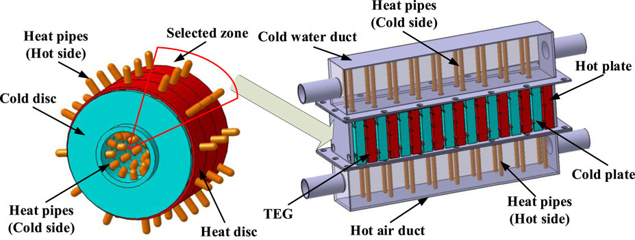
FIGURE 1. TEG device similar conversion.
In order to obtain the heat transfer performance, the type-K thermocouples with an accuracy of ±0.4% are arranged in some cold plate surfaces and hot plate surfaces, as shown in Figure 2. Some are utilized to measure the cold side temperatures, while the others are utilized to measure the hot side temperatures. The TEG is surrounded by thermal insulation to prevent the heat from being transferred to the outside. There are five TEG pieces which are arranged as the thermocouples, No. 1, No. 5, No. 9, No. 13, and No. 17. The cold side temperature values are indicated, respectively, by T.1, T.3, T.5, T.7, and T.9, and the hot side temperature values are indicated, respectively, by T.2, T.4, T.6, T.8, and T.10.
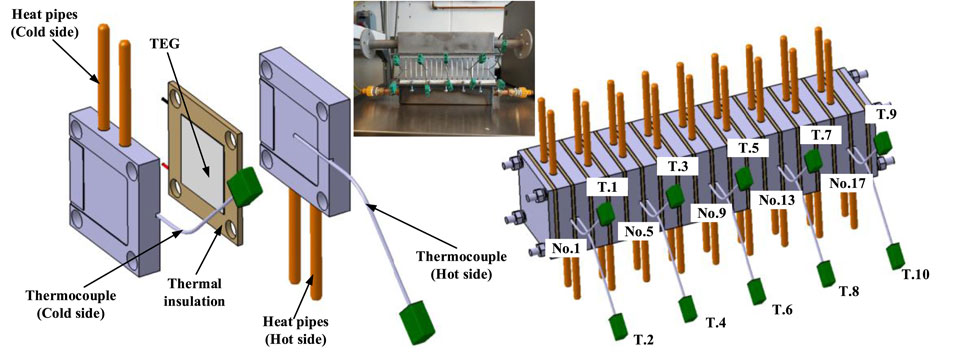
FIGURE 2. Temperature sample points setting.
Experimental System Setup
After completing the above structural design, it is necessary to provide the TEG with a heat source and a cold source. A corresponding test system is needed, as shown in Figures 3A,B. A TEG experimental system includes three parts: a heat source supply and test system, a cold source supply and test system, and a test system for the TEG.
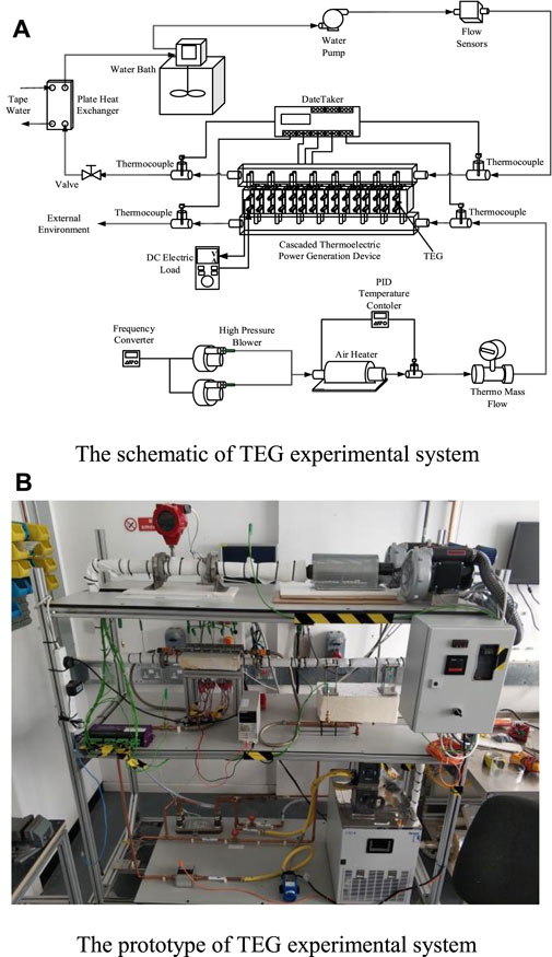
FIGURE 3. (A) Schematic of the TEG experimental system. (B) Prototype of the TEG experimental system.
The heat source supply and test system include thermocouples, high-pressure blowers, an air heater, and a thermo-mass flow sensor. The thermocouples are used to measure the temperatures of the hot air inlet and outlet. The high-pressure blowers, which include two blowers, can supply the air volume. With the frequency converter, the high-pressure blowers can supply different air volumes. Through the air heater, the air can be heated to the specified temperature with the temperature controller. The thermo-mass flow sensor (Quadra Therm 780i) with an accuracy of 0.5 can measure the air volume with the specified temperature and flow. The cold source supply and test system include thermocouples, a valve, a water pump, a plate heat exchanger, a water bath, and a flow sensor. The thermocouples are utilized to measure the temperatures of the cold water inlet and outlet. The valve is a slide valve which can adjust the flow. The plate heat exchanger can exchange heat with tap water. Using the tap water to reduce the temperature of the water which has been heated, exchanging with heat pipes, the load of the water bath can be reduced. The water bath is used to cool the water and supply the water at a constant temperature. The flow sensor (IFM SU7000) is used to measure the flow with an accuracy less than ±3%MW + 0.2%MEW.
The test system for the TEG includes temperature measurement and power measurement. The data taker (DT85M) is used to measure the temperatures of the TEG cold sides and hot sides. It can also be used to measure the temperatures of hot air and cold water. In order to measure the power generation of the TEG, the DC electric load (BK8540) is used to measure the power generation in the suitable external resistance.
In order to obtain the power generation performance and temperature characteristics, the air flow and water flow are set to various conditions. The air flow is controlled by the frequency converter, and the frequency is set to 30, 35, 40, 45, 50, 55, 60, 70, and 75, as shown in Figure 4. The corresponding air flow can be changed with the frequency. The water flow is set to 3 L/min, 4 L/min, 5 L/min, 6 L/min, 7 L/min, 8L/min, and 9 L/min. The flow direction is utilized by way of the same direction, that is, the air flow direction is the same as the water flow direction.
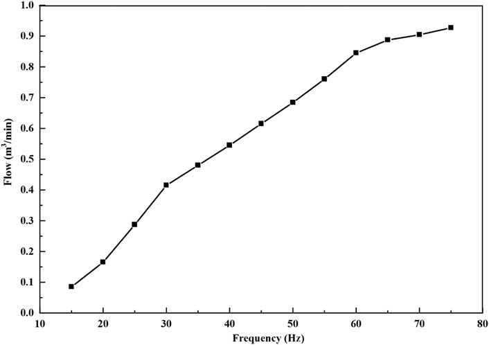
FIGURE 4. Air flow curve with frequency.
The hot air temperature is usually stable in the vehicle exhaust gas. The heat source is set to a fixed temperature. In order to keep the thermo-mass flow sensor operating safely, the heat source temperature is set to 200°C. So the hot air inlet temperature is about 180°C and the cold source temperature is set to 15°C for getting a big temperature difference. Because of the heat transfer inside the ducts, the temperature in both sides of the TEG will be lower than the temperature of the cold and heat sources. In order to analyze the power in a high Td, a single TEG is tested first with different temperature differences, as shown in Figure 5. It is the power performance when the external resistance is 3.5 Ω. The power generation, voltage, and current are changed linearly with the Td. So the power performance of high Td conditions can be obtained and analyzed through analyzing the low Td conditions. Meanwhile, the power generation performances will be changed under different external resistances, as shown in Figure 6. It is the power performance when the Td is 55°C. When the external resistance is 3.5 Ω, the power generation is an optimal value. So the external resistance is defined as 59.5 Ω when the TEG group experiment is done.
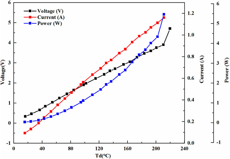
FIGURE 5. Single TEG power generation performance with the Td.
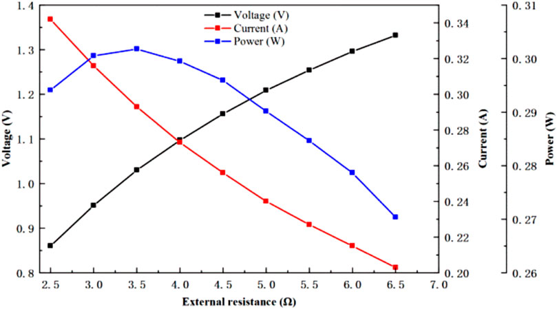
FIGURE 6. Power performance curve with resistance.
Results and Discussion
Power Generation Performance
The power generation performance is shown in Figures 7A,B. The power and voltage are both increased with air and water flow increasing. It can be seen from the power and voltage curves that the water flow has a smaller effect on the power generation than the air flow. Special working conditions are selected to compare the different effects. When the water flow is 6 L/min and the air flow is between 0.415 m3/min and 0.927 m3/min, the power is increased from 0.639 to 1.6 W and the voltage is increased from 6.2 to 9.817 V. However, when the air flow is 0.684 m3/min and the water flow is between 3L/min and 9L/min, the power is only increased from 1.179 to 1.268 W and the voltage is increased from 8.415 to 8.69 V. As can be seen, the air flow has a bigger effect on power and voltage than the water flow. So the air flow is the main influencing factor for the TEG group on the power generation characteristics.
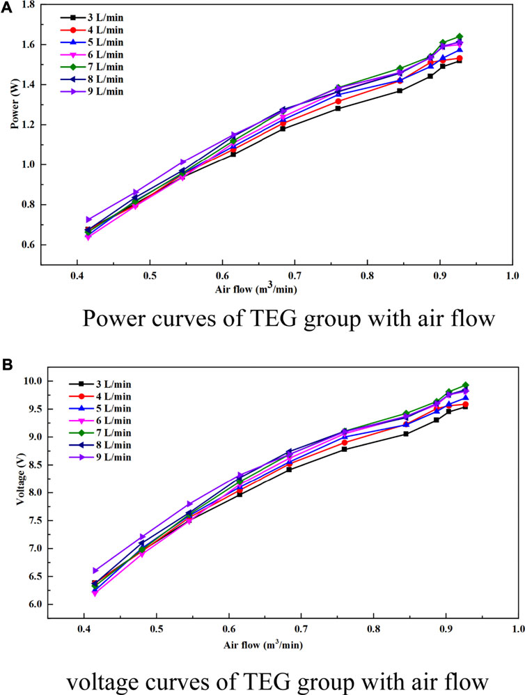
FIGURE 7. (A) Power curves of the TEG group with air flow. (B) Voltage curves of the TEG group with air flow.
Temperature Characteristics
For the TEG, the temperatures on both sides of the TEG are important factors affecting the power generation. The hot side temperature, cold side temperature, and Td are utilized to analyze the power generation of the TEG group. The special working condition is that the air flow is 0.684 m3/min and the water flow is 6 L/min. As shown in Figure 8, it is seen that the cold side temperature curve showed a gradual upward trend, and the hot side temperature curve showed a wave trough phenomenon. The temperatures on both sides of the TEG make it so that the Td curve also showed a wave trough phenomenon. The lowest value of the hot side temperature is also concentrated near TEG No. 13.
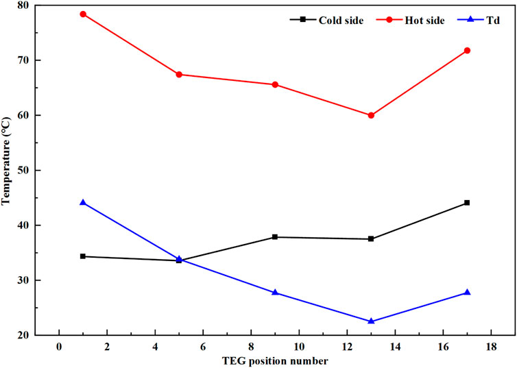
FIGURE 8. Temperature curves with different TEGs.
In the duct structure of the TEG group, the section size of the duct is 65 × 65 mm, and the air outlet size is 15 mm in diameter. This has a big cross section difference and causes the hot air to reflow at the end of the duct. Because of this, the heat pipes can get more heat at the end of the duct, and the hot side temperature at the end of the duct can be increased. On the other hand, the air inlet temperature is 173.5°C, and the air outlet temperature is 138.59°C. The big temperature difference between the air inlet and the air outlet makes the hot side temperature show a significant downward trend. On integrating the air reflow and the temperature-significant downward trend, the hot side temperature curve showed a wave trough phenomenon. The cold side duct also has the reflow and the temperature difference between the water inlet and the water outlet. The water inlet temperature is 15.19°C, and the outlet temperature is 16.08°C. Due to the temperature difference between the water inlet and the water outlet being small, the cold side temperature curve also has a slight upward trend.
The air flow can affect the hot side temperature and the cold side temperature, as shown in Figures 9A,B. When the water flow is 6 L/min, temperatures of both sides of the TEG are increased with the air flow increase. The cold side temperature curves showed a gradual upward trend with the TEG position in the different air flows, the hot side temperature curves showed a wave trough phenomenon, and the air flow increased the temperature of the hot side more than that of the cold side. Although the air flow increasing causes temperatures on both sides to be increased, the cold side temperature curves still have the same gradual upward trend, and the hot side temperature curves still have the same wave trough phenomenon, as shown in Figure 10. The Td curves have the wave trough phenomenon. This is the result of a combination of the cold side temperature and the hot side temperature. The air flow increasing can also improve the Td value of all the TEGs, and the wave trough phenomenon cannot be weakened.
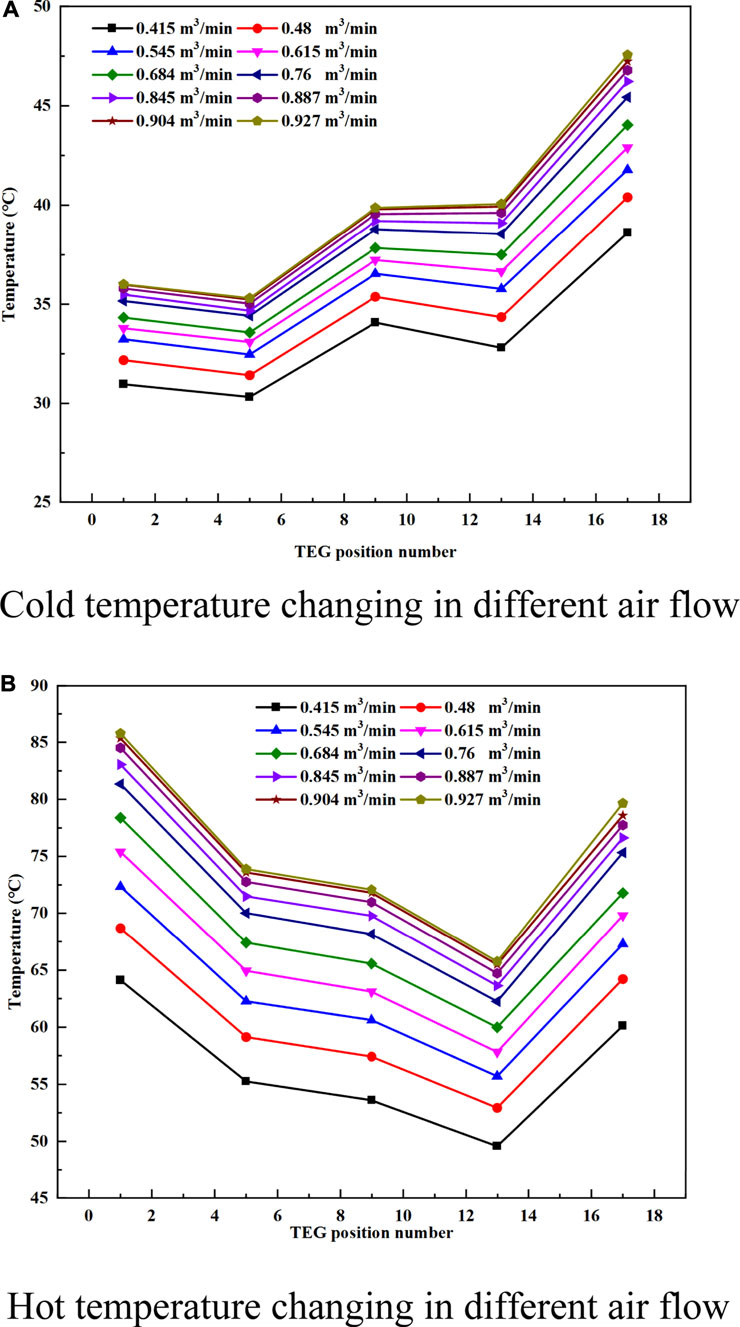
FIGURE 9. (A) Cold temperature changing in different air flows. (B) Hot temperature changing in different air flows.
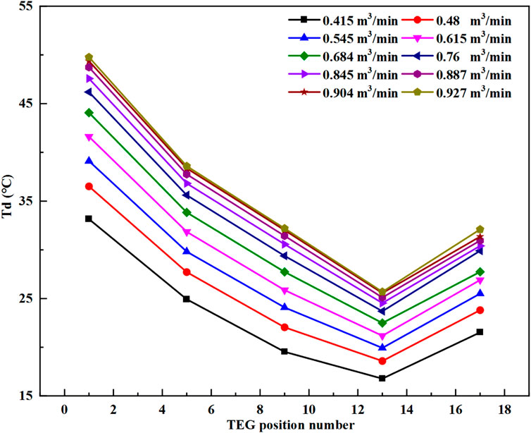
FIGURE 10. Td curves in different air flows.
The Td values in the different TEGs are selected to analyze the effect of the air flow increases, as shown in Figure 11. All the Td values are increased with the air flow increases, which are basically parallel. So the increase in temperature values is basically consistent.
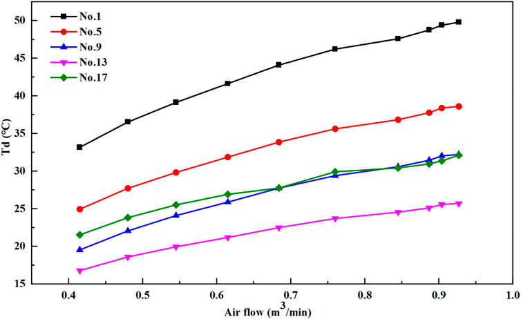
FIGURE 11. Td curves with air flow in different TEGs.
The water flow can also affect the hot side temperature and the cold side temperature, as shown in Figures 12A,B. The air flow is 0.684 m3/min, same as the air flow; the cold side temperature curves also showed a gradual upward trend with the TEG position. The hot side temperature curves showed the wave trough phenomenon in the different water flows, too. The water flow increasing causes a smaller change in temperature than the air flow increases. The water flow also causes a decrease in temperature on both sides.
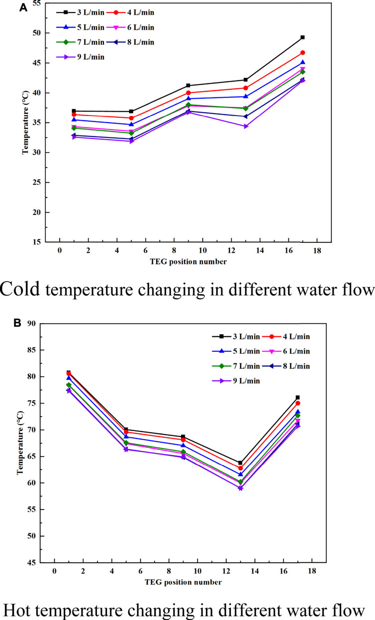
FIGURE 12. (A) Cold temperature changing in different water flows. (B) Hot temperature changing in different water flows.
As shown in Figure 13, the Td curves show the wave trough phenomenon. The increasing water flow has little effect on weakening the wave trough phenomenon, and the Td values are almost not changed with the water increases. It is also shown in Figure 14 that the Td curves are almost horizontal, which means that the water flow changing cannot improve the Td value obviously. The reason is that the heat pipes in the cold side are cooled by water. The water has high heat transfer ability. The flow change cannot have a big effect on the convective heat transfer coefficient. So the flow change has little effect on the heat transfer between the heat pipes and the water.
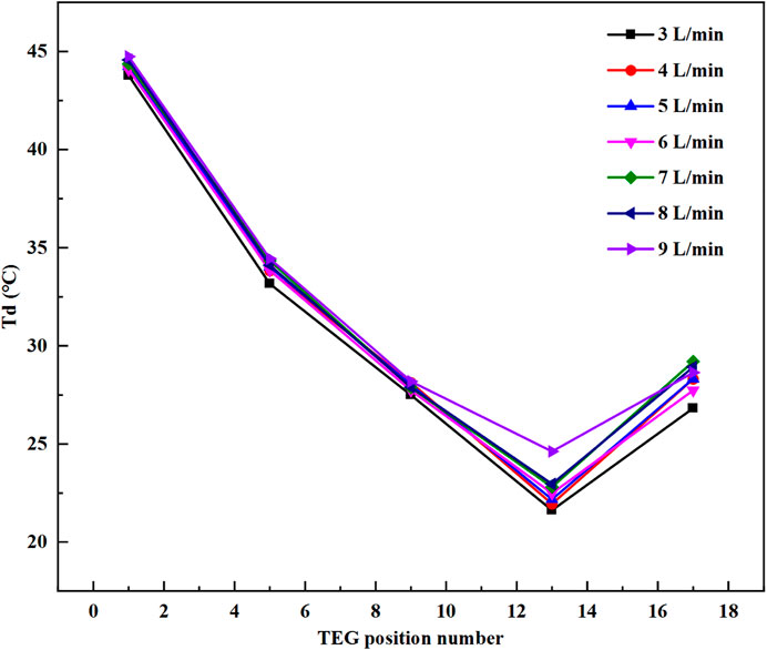
FIGURE 13. Td curves in different water flows.
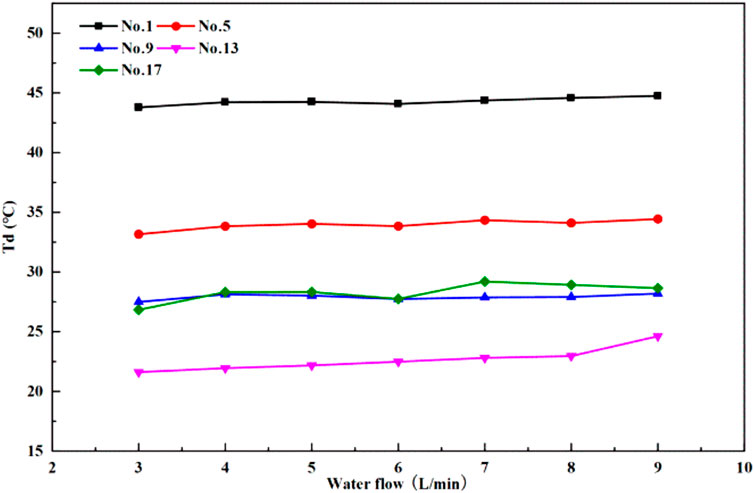
FIGURE 14. Td curves with air flow in different TEGs.
Conclusion
The TEG group device is built for analyzing the performance of the disc sandwich structure. 17 sets of TEG units are included in the TEG group device for analyzing the temperature distribution along the flow direction. The cold plate and the hot plate are used as the cold side and the hot side of the different TEG pieces simultaneously. The heat pipes are used to transfer the heat of the cold and hot sides while ensuring the high heat transfer coefficient. They can make as many TEG pieces as possible on the exhaust pipe per unit length. By analyzing different air flows and water flows, some results are obtained.
1) The power and voltage can be increased with the air flow or water flow increasing; the water flow has a smaller effect on the power generation than the air flow.
2) In the TEG group, the cold side temperature showed a gradual upward trend, the hot side temperature showed a wave trough phenomenon, and the Td showed a wave trough phenomenon.
3) The hot air flow and the cold water changing cannot weaken the temperature trend of the hot side and the cold side. The hot air flow can more significantly increase the Td than the cold water.
4) The hot side temperature distribution is mainly affected by the hot air flow, and the main influence of the cold side temperature distribution is from the hot side temperature. The effect on the water side is not obvious.
Data Availability Statement
The raw data supporting the conclusion of this article will be made available by the authors, without undue reservation.
Author Contributions
YL and ZS performed the data analyses and wrote the manuscript; GW contributed to the conception of the study and performed the experiment; YY provided the experimental site, equipment, and other material resources related to the experiment; YZ provided corresponding technical support. All authors contributed to the article and approved the submitted version.
Funding
The work is supported by Double Ten “Science and Technology Innovation Project of Jilin Province of China” NO. 17SS022. The work is also supported by the China Scholarship Council (CSC) for the first author’s scholarship.
Conflict of Interest
The authors declare that the research was conducted in the absence of any commercial or financial relationships that could be construed as a potential conflict of interest.
Publisher’s Note
All claims expressed in this article are solely those of the authors and do not necessarily represent those of their affiliated organizations, or those of the publisher, the editors, and the reviewers. Any product that may be evaluated in this article, or claim that may be made by its manufacturer, is not guaranteed or endorsed by the publisher.
References
Ahmadi Atouei, S., Ranjbar, A. A., and Rezania, A. (2017). Experimental investigation of two-stage thermoelectric generator system integrated with phase change materials. Appl. Energ. 208, 332–343. doi:10.1016/j.apenergy.2017.10.032
Aranguren, P., Astrain, D., Rodríguez, A., and Martínez, A. (2015). Experimental investigation of the applicability of a thermoelectric generator to recover waste heat from a combustion chamber. Appl. Energ. 152, 121–130. doi:10.1016/j.apenergy.2015.04.077
Cao, Q., Luan, W., and Wang, T. (2018). Performance enhancement of heat pipes assisted thermoelectric generator for automobile exhaust heat recovery. Appl. Therm. Eng. 130, 1472–1479. doi:10.1016/j.applthermaleng.2017.09.134
Dai, D., Zhou, Y., and Liu, J. (2011). Liquid metal based thermoelectric generation system for waste heat recovery. Renew. Energ. 36 (12), 3530–3536. doi:10.1016/j.renene.2011.06.012
Date, A., Date, A., Dixon, C., and Akbarzadeh, A. (2014). Theoretical and experimental study on heat pipe cooled thermoelectric generators with water heating using concentrated solar thermal energy. Solar Energy 105, 656–668. doi:10.1016/j.solener.2014.04.016
Fernández-Yañez, P., Armas, O., Capetillo, A., and Martínez-Martínez, S. (2018). Thermal analysis of a thermoelectric generator for light-duty diesel engines. Appl. Energ. 226, 690–702. doi:10.1016/j.apenergy.2018.05.114
Huang, B.-J., Hsu, P.-C., Tsai, R.-J., and Hussain, M. M. (2015). A thermoelectric generator using loop heat pipe and design match for maximum-power generation. Appl. Therm. Eng. 91, 1082–1091. doi:10.1016/j.applthermaleng.2015.08.059
Ishiyama, T., and Yamada, H. (2012).Effect of heat pipes to suppress heat Leakage for thermoelectric generator of energy harvesting. Renewable Energy Research and Applications (ICRERA), 2012 International Conference on. IEEE. New Jersey doi:10.1109/icrera.2012.6477306
Jang, J.-C., Chi, R.-G., Rhi, S.-H., Lee, K.-B., Hwang, H.-C., Lee, J.-S., et al. (2015). Heat Pipe-Assisted Thermoelectric Power Generation Technology for Waste Heat Recovery. J. Elec Materi 44 (6), 2039–2047. doi:10.1007/s11664-015-3653-4
Jang, J.-Y., Tsai, Y.-C., and Wu, C.-W. (2013). A study of 3-D numerical simulation and comparison with experimental results on turbulent flow of venting flue gas using thermoelectric generator modules and plate fin heat sink. Energy 53, 270–281. doi:10.1016/j.energy.2013.03.010
Kim, P.-J., Rhi, S.-H., Lee, K.-B., Hwang, H.-C., Lee, J.-S., Jang, J.-C., et al. (2014). Heat-Pipe-Associated Localized Thermoelectric Power Generation System. J. Elec Materi 43 (6), 1613–1619. doi:10.1007/s11664-013-2807-5
Kim, S.-K., Won, B.-C., Rhi, S.-H., Kim, S.-H., Yoo, J.-H., and Jang, J.-C. (2011). Thermoelectric Power Generation System for Future Hybrid Vehicles Using Hot Exhaust Gas. J. Elec Materi 40 (5), 778–783. doi:10.1007/s11664-011-1569-1
Kim, S., Park, S., Kim, S., and Rhi, S.-H. (2011). A Thermoelectric Generator Using Engine Coolant for Light-Duty Internal Combustion Engine-Powered Vehicles. J. Elec Materi 40 (5), 812–816. doi:10.1007/s11664-011-1580-6
Li, B., Akdogan, V., Li, Y., Yan, Y., Li, J., and Wang, J. (2015). A novel and efficient thermoelectric-generating (TEG) system of energy harvesting from exhaust gases of passenger vehicles. VTMS 1, 54–61.
Li, B., Huang, K., Yan, Y., Li, Y., Twaha, S., and Zhu, J. (2017). Heat transfer enhancement of a modularised thermoelectric power generator for passenger vehicles. Appl. Energ. 205, 868–879. doi:10.1016/j.apenergy.2017.08.092
Liu, T., Wang, T., Luan, W., and Cao, Q. (2017). Optimal Number of Thermoelectric Couples in a Heat Pipe Assisted Thermoelectric Generator for Waste Heat Recovery. J. Elec Materi 46 (5), 3137–3144. doi:10.1007/s11664-016-5223-9
Lv, S., He, W., Jiang, Q., Hu, Z., Liu, X., Chen, H., et al. (2018). Study of different heat exchange technologies influence on the performance of thermoelectric generators. Energ. Convers. Manag. 156, 167–177. doi:10.1016/j.enconman.2017.11.011
Mohamed, E. S. (2019). Development and performance analysis of a TEG system using exhaust recovery for a light diesel vehicle with assessment of fuel economy and emissions. Appl. Therm. Eng. 147, 661–674. doi:10.1016/j.applthermaleng.2018.10.100
Orr, B., Akbarzadeh, A., Mochizuki, M., and Singh, R. (2016). A review of car waste heat recovery systems utilising thermoelectric generators and heat pipes. Appl. Therm. Eng. 101, 490–495. doi:10.1016/j.applthermaleng.2015.10.081
Orr, B., Singh, B., Tan, L., and Akbarzadeh, A. (2014). Electricity generation from an exhaust heat recovery system utilising thermoelectric cells and heat pipes. Appl. Therm. Eng. 73 (1), 588–597. doi:10.1016/j.applthermaleng.2014.07.056
O’Shaughnessy, S. M., Deasy, M. J., Kinsella, C. E., Doyle, J. V., and Robinson, A. J. (2013). Small scale electricity generation from a portable biomass cookstove: Prototype design and preliminary results. Appl. Energ. 102, 374–385.
Rea, J. E., Oshman, C. J., Singh, A., Alleman, J., Parilla, P. A., Hardin, C. L., et al. (2018). Experimental demonstration of a dispatchable latent heat storage system with aluminum-silicon as a phase change material. Appl. Energ. 230, 1218–1229. doi:10.1016/j.apenergy.2018.09.017
Rezania, A., and Rosendahl, L. A. (2012). New Configurations of Micro Plate-Fin Heat Sink to Reduce Coolant Pumping Power. J. Elec Materi 41 (6), 1298–1304. doi:10.1007/s11664-011-1887-3
Riffat, S. B., and Ma, X. (2003). Thermoelectrics: a review of present and potential applications. Appl. Therm. Eng. 23 (8), 913–935. doi:10.1016/s1359-4311(03)00012-7
Twaha, S., Zhu, J., Yan, Y., and Li, B. (2016). A comprehensive review of thermoelectric technology: Materials, applications, modelling and performance improvement. Renew. Sust. Energ. Rev. 65, 698–726. doi:10.1016/j.rser.2016.07.034
Wang, T., Luan, W., Liu, T., Tu, S.-T., and Yan, J. (2016a). Performance enhancement of thermoelectric waste heat recovery system by using metal foam inserts. Energ. Convers. Manag. 124, 13–19. doi:10.1016/j.enconman.2016.07.006
Wang, X., Li, B., Yan, Y., Liu, S., and Li, J. (2016b). A study on heat transfer enhancement in the radial direction of gas flow for thermoelectric power generation. Appl. Therm. Eng. 102, 176–183. doi:10.1016/j.applthermaleng.2016.03.063
Wang, Y., Li, S., Xie, X., Deng, Y., Liu, X., and Su, C. (2018). Performance evaluation of an automotive thermoelectric generator with inserted fins or dimpled-surface hot heat exchanger. Appl. Energ. 218, 391–401. doi:10.1016/j.apenergy.2018.02.176
Keywords: TEG group, heat pipe, similar sandwich structure, power generation performance, temperature characteristics
Citation: Liu Y, Shi Z, Wang G, Yan Y and Zhang Y (2021) Experimental Investigation for a Novel Prototype of a Thermoelectric Power Generator With Heat Pipes. Front. Energy Res. 9:744366. doi: 10.3389/fenrg.2021.744366
Received: 20 July 2021; Accepted: 13 August 2021;
Published: 20 September 2021.
Edited by:
Cong Qi, China University of Mining and Technology, ChinaReviewed by:
Juan Li, Nanjing Forestry University, ChinaXuezhi Zhou, Institute of Engineering Thermophysics (CAS), China
Copyright © 2021 Liu, Shi, Wang, Yan and Zhang. This is an open-access article distributed under the terms of the Creative Commons Attribution License (CC BY). The use, distribution or reproduction in other forums is permitted, provided the original author(s) and the copyright owner(s) are credited and that the original publication in this journal is cited, in accordance with accepted academic practice. No use, distribution or reproduction is permitted which does not comply with these terms.
*Correspondence: Guohua Wang, d2FuZ2doQGpsdS5lZHUuY24=