 Yiyan Lu
 Zhao Liu
 Jianguo Lyu1
- 1School of Automation Engineering, Nanjing University of Science and Technology, Nanjing, China
- 2State Key Laboratory of Smart Grid and Control, Nanjing, China
- 3NR Electric Co., Ltd, Nanjing, China
Hybrid energy storage system (HESS) using cascaded multilevel converters (CMC) has received increasing attention due to its merits on smoothing power fluctuations for renewable energy systems (RESs). However, CMC-based HESS still faces tough challenges due to asymmetrical ac power distribution. In this paper, hierarchical power allocation control strategy is utilized in CMC-based star-connected HESS to coordinate power between batteries and supercapacitors (SCs). Using the proposed power allocation mechanism, energy management strategy (EMS) with two operation modes can be achieved, which includes SC voltage regulation mode and power compensation mode. In SC voltage regulation mode, SC voltages are regulated to achieve long-term stable operation. Power compensation mode aims to allocate the active power fluctuation and employs SCs to mitigate it. Meanwhile, the principle of the hierarchical power allocation strategy is analyzed to facilitate the accurate control and flexible switching of different operation modes. A series of simulation and experiment tests are executed to demonstrate the performance of the proposed control strategy.
Introduction
Renewable energy systems (RESs), especially wind power systems and photovoltaic (PV) systems, have been globally installed in dc-ac micro-grids in recent years (Liao et al., 2017; Kavousi et al., 2018; Chen et al., 2021). However, the intermittent power generation is still a tough challenge for RESs. Consequently, energy storage system (ESS) has received increasing attention due to its merits on smoothing output fluctuations for improved power quality (Li et al., 2019; Li et al., 2020a; Hargreaves and Jones, 2020). Energy storage devices (ESDs) are the key components for ESSs. They are characterized based on energy density, power density, ramp rate, and life cycle, etc. However, none of the existing ESDs can fulfill all expected features simultaneously, e.g., batteries have high energy density for long-term operation but limited ramp rate, and supercapacitors (SCs) have high power density and ramp rate for short-term fluctuations but low energy density (Riboldi et al., 2020; Xiao et al., 2015). Hence, ESSs integrated by single type of ESD require higher cost and size to meet all the demands for power density, energy density, and ramp rate. To overcome the shortage of the existing single-type-ESD ESSs, hybrid energy storage system (HESS) is dramatically employed as an effective solution to handle power fluctuations caused by RESs (Wickramasinghe Abeywardana et al., 2017). In most applications, HESSs are integrated by batteries and SCs to make full use of their advantages, which can reduce the size of the system, extend the lifetime and attenuate the thermal stresses of batteries (Lahyani et al., 2013; Kollimalla et al., 2014; Zhang L et al., 2019; Li et al., 2020b).
For the HESS in dc-ac micro-grids, the design of power converter is challenging. Conventionally, ESSs in dc-ac micro-grids are connected to low voltage (LV) distributed networks, employing two-level converters and dc-dc interfaces (Clerici et al., 2018), (Kim et al., 2018). However, these topologies have limitations when connecting to mid voltage (MV) or high voltage (HV) grids for the following reasons (Jiang et al., 2019):
1) Large amounts of ESSs should be connected in series to form high voltage dc (HVDC), and consequently, power electronic devices with rapid switching frequency are required. Moreover, balancing of the high-voltage battery pack is challenging which reduces the lifetime of batteries.
2) With limited number of voltage levels, the output quality is low. Hence, step-up transformers are commonly necessary to connect the MV/HV grids, which leads to higher cost and lower efficiency.
Cascaded multilevel converter (CMC) is a promising structure for MV/HV applications (Wang et al., 2019). Ac capability is improved by series connection of converter cells, and harmonics distortion is reduced due to increased voltage levels. Moreover, segmented dc sources can ease the energy management for ESS. Unfortunately, most of the existing CMC-based ESS employs single-type-ESD. In this condition, output voltages of H-bridges are identical and the synchronous ac current leads to the symmetrical power distribution (Yu et al., 2016; Lee et al., 2018). For HESS, the power distribution among converter cells should be asymmetrical to fulfill the operation requirements of the hybrid dc sources; hence, the power allocation strategy is difficult and critical for CMC-based HESS.
As synchronous ac current flows through all the converter arms of the CMC-based HESS, asymmetrical power allocation means to distribute the overall output voltage asymmetrically. Feed-forward mechanism is a promising method for asymmetrical power distribution.Jiang et al. (2018) employed feed-forward space-vector-modulation (FFSVM) technique for single-phase CMC-based battery-SC HESS, which can flexibly distribute power among converter cells. However, the FFSVM algorithm is time consuming especially when the number of cascaded cells is large (Jiang et al., 2021). In Wang et al. (2017), Zha et al. 2017, Zhang Y et al. (2019), the phase shift between the output voltages of clusters and the output current are calculated according to the requirement of dc sources. With different phase shift, the output power of different ESDs can be distributed asymmetrically. These individual phase control methods are easy to achieve, nevertheless, large amounts of trigonometric functions lead to complicated calculations and the dual-loop controller worsen the dynamics performance. Hierarchical structure is another solution for simplification (Kim et al., 2019). By dividing the variables such as current and dc voltages into layers, numbers of states to be considered is reduced. Feng et al. (2019) employs hierarchical structure in grid-connected CMC-based PV-battery system. The upper layer of the controller regulates the output current and calculates the synthesized output voltage, while the lower layer distributes power between PV and battery cells. By this method, the output voltage of battery cells can be derived from the deviation between PV generation and the synthesized output voltage command; meanwhile, dual-loop controller is avoided by the hierarchical mechanism.
Meanwhile, the energy management strategy (EMS) is required for battery-SC HESS. In Zhang and Li (2020), an EMS based on fuzzy logic control (FLC) is designed for HESS in electrical vehicles (EVs) to regulate SCs at a desired state of charge (SOC), where SCs have enough charge for acceleration process and enough space for absorbing braking energy. A real-time optimization is presented by (Choi et al., 2014) to compute SOC of SCs according to the output demand dynamics and optimize power flow through the HESS simultaneously. Moreover, multiple operation modes have been used for the EMSs of battery-SC HESS to flexibly change the power distribution according to the output demand (Jiang et al., 2018; Akar et al., 2017). In Jiang et al. (2018), three operation modes, including high power output mode, normal operation mode, and reverse power absorption mode are proposed to control SCs for different conditions. These operation modes are switched by the dispatch of micro-grid centralized controller (MGCC) and SOC of SCs. Akar et al. (2017) presents discharging mode, charging/discharging mode, and regenerative mode for battery-SC HESS in EVs, and simultaneously, an operation mode switching method is given considering battery generation and output demand levels. However, with multiple operation modes, the mode switching algorithm is complicated.
In this paper, a hierarchical power allocation control strategy is designed for the battery-SC HESS to solve the following challenges:
1) CMC structure is employed for the HESS to solve the limitations of the conventional two-level converters, such as rapid switching frequency, lower efficiency and higher output distortion.
2) The power distribution for asymmetrical CMC is challenging; moreover, most of the existing power allocation strategies based on individual phase control are complicated. The hierarchical power allocation strategy proposed in this paper divides current control and power allocation into layers, which can flexibly distribution power between different ESDs and meet the grid dispatch simultaneously. In addition, the calculation is less time consuming under dq rotating frame and the dynamic performance is optimized without dual-loop controller.
3) Different from the existing EMS with multiple operation modes, only two operation modes are designed for the CMC-based HESS according to grid dispatch and SOC of SCs, which can realize long-term stable operation and short-term power compensation as well. With the simplified EMS, the switching algorithm is easy to be achieved.
This paper is organized as follows. The system topology and EMS for the HESS are respectively presented in System Topology and Energy Management Strategy of the HESS. In Hierarchical Power Allocation Control, the hierarchical power allocation control is proposed to fulfill the EMS. The active power capacity of the HESS is analyzed in Active Power Capacity of the HESS to facilitate the design of the system. Simulation and Experimental Verification gives the simulation and experimental results. Finally, conclusions are drawn in Conclusion.
System Topology and Energy Management Strategy of the HESS
System Topology
Figure 1 depicts the CMC-based star-connected battery-SC hybrid energy storage system (HESS) and the detailed structure of phase A. Each phase of the system is constituted by a battery cluster and SC cluster, where the battery cluster contains M battery converter cells and SC cluster contains N SC converter cells. Each ESD is connected in parallel with an H-bridge, and all the H-bridges in an individual phase are connected in series. Vbat and VSC are respectively the dc voltage of battery and SC cell. vXbi (i = 1,…, M) and vXcj (j = 1,…, N) separately represent the output voltage of battery and SC cell in phase X (X = A, B, C). vXbΣ and vXcΣ are the output voltage of battery and SC cluster, vsX is grid voltage, isX is the output current with the direction shown in Figure 1, and L is the filter inductance.
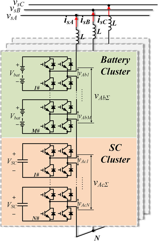
FIGURE 1. Circuit configuration of star-connected battery-SC HESS using CMC.
In the battery-SC HESS, flexible power distribution is crucial to fulfill different requirements and make full use of these two ESDs. Hence, an energy management strategy (EMS) with several operation modes is inevitable.
Energy Management Strategy for the HESS
The HESS aims to maximize the advantages of both batteries and SCs. With high energy density, batteries are promising for long-term power supply. Meanwhile, with high power density and ramp rate, SCs are suitable to mitigate short-term fluctuations. To flexibly distribute power between batteries and SCs, the EMS contains two operation modes, as shown in Figure 2:
1) SC voltage regulation mode (Mode I): This mode is employed to regulate SC voltages in a certain range. It can be used to achieve the long-term stable operation of the HESS. In this condition, batteries provide rated active power Pr for the grid and SCs maintain their voltages at a desired value, where they have enough charge and space for active power fluctuations.
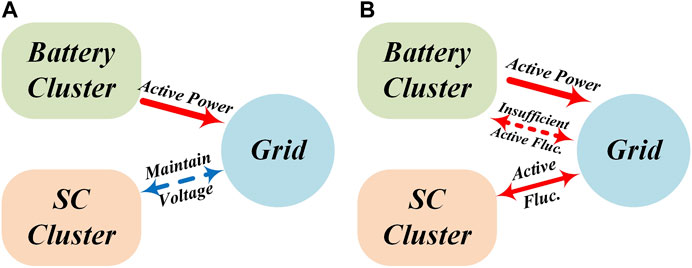
FIGURE 2. Active power flow of different operation modes; (A) SC voltage regulation mode; (B) Power compensation mode.
In addition, when SC voltages reach their upper/lower limit during charge/discharge process, this mode is also activated to regulate SC voltages at their upper/lower limit.
2) Power compensation mode (Mode II): In this mode, SCs charge/discharge to mitigate the active power fluctuation. Meanwhile, batteries still supply rated active power for the grid. If the active fluctuation cannot be provided merely by SCs, batteries will the supply the insufficient active fluctuation.
The operation mode switching algorithm of the HESS is illustrated in Figure 3. First, by comparing the active power command P∗ and the rated active power Pr, whether SCs should charge/discharge to mitigate active fluctuations can be determined. Then, according to the SOC of SCs, the suitable operation mode of the HESS is selected. When P∗ = Pr, no active fluctuations need to be eliminated by SCs. In this condition, SOC of SCs should be corrected to the desired value for future active fluctuations. Hence, SC voltage regulation mode (Mode I) is activated to control VSCΣav at the desired value VSCΣr. If P∗ is not equal to Pr, SCs should charge/discharge to eliminate active fluctuations, and consequently, power compensation mode (Mode II) is activated. When VSCΣ reaches the upper/lower limits, Mode I is activated to regulate VSCΣav at upper/lower limits.
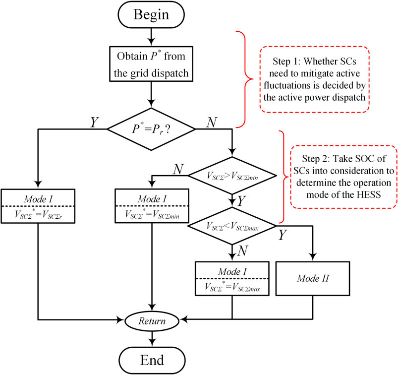
FIGURE 3. Flowchart of operation mode switching algorithm.
In order to realize the EMS of the HESS, this paper employs asymmetrical power allocation strategy with hierarchical structure for flexible power distribution between batteries and SCs.
Hierarchical Power Allocation Control
Hierarchical Control for the Battery-SC HESS
In this paper, the control strategy designed for the CMC-based star-connected battery-SC HESS employs hierarchical structure to distribute power flexibly with reduced system complicity. Using the hierarchical mechanism, the control system is divided into upper layer and lower layer as shown in Figure 4.
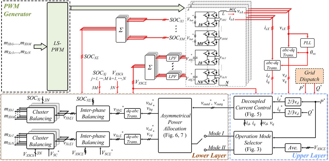
FIGURE 4. Overall control block diagram.
The upper layer regulates the overall output power of the HESS and calculates the synthesized output voltage reference for the lower layer. The decoupled current control based on dq rotating frame is used in this paper as shown in Figure 5. Note that the current control method has been widely discussed such as in (Liming Liu et al., 2015), (Koyama et al., 2018), it will be only reviewed briefly to facilitate the design of lower layer controller.

FIGURE 5. Current control based on dq frame.
According to Figure 5, the active and reactive current reference id* and iq* can be respectively derived from the grid active and reactive power dispatch P* and Q*. The d- and q-axis of grid voltage vd and vq, and voltage across the filter inductor L are used in the feed-forward control. Hence, the d- and q-axis voltage references of the system voutd* and voutq* can be calculated as:
where Kip and Kii are the proportional and integral gain of the current control, and ω is the angular speed of the grid voltage.
With the overall output voltage references calculated by the decoupled current control, the asymmetrical power allocation in the lower layer will distribute the power between batteries and SCs according to the operation mode. Details of the asymmetrical power allocation are described in the following subsection. In addition, interphase and cluster balancing control are respectively utilized for batteries and SCs (Maharjan et al., 2009; Liu et al., 2012; Koyama et al., 2018).
Level shifted pulse-width modulation (LS-PWM) is used for low harmonics distortion and simple calculation (Adam et al., 2015; Aneesh Kumar et al., 2015).
Asymmetrical Power Allocation Strategy
To distribute power between batteries and SCs flexibly, the asymmetrical power allocation strategy utilizes feed-forward mechanism and calculates the output voltage of SC clusters according to the operation mode; then, the output voltage of battery clusters can be derived from the deviations the overall output voltage and the SC cluster output voltage. In this subsection, the power distribution strategy of different operation modes will be described seriatim.
Mode I: SC Voltage Regulation Mode
The SC voltage regulation mode aims to maintain the dc voltages of SCs. Figure 6 depicts the SC control strategy in this mode which regulates the mean value of VSCΣ by adjusting the output power of SC clusters. Note that SC clusters merely provide reactive power for the grid in this process, the following equation can be obtained:
where vcdff and vcqff respectively represent the d- and q-axis of the feedforward output voltage of SC clusters, and Qc* is the desired reactive power generation of SC clusters.
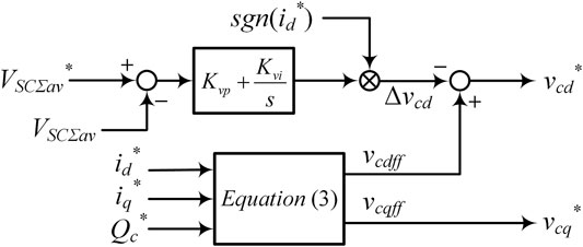
FIGURE 6. SC voltage regulation strategy.
According to (2), vcdff and vcqff can be respectively calculated by id*, iq* and Qc* as:
To achieve accurate voltage regulation for SCs, the deviations between the desired and the actual voltage of SCs should be eliminated. Consequently, a control variable Δvcd is subtracted from vcdff to change the charge/discharge state of SCs as follows:
Moreover, the control variable Δvcd is given by the improved PI controller as:
where Kvp and Kvi are respectively the proportional and integral gain, and sgn (x) is a sign function defined as follows:
Different from conventional PI controller for voltage regulation, the active current reference also affects the charge/discharge state of SCs in this condition. When id∗ > 0, subtracting positive Δvcd will charge SCs, and subtracting negative Δvcd will discharge SCs; nevertheless, the charge/discharge state of SCs are exactly contrary when id∗ < 0. Hence, the sign of id∗ is multiplied with the PI controller.
Mode II: power Compensation Mode
In this mode, SCs are used to mitigate active fluctuations, the detailed SC cluster voltage calculating algorithm is depicted in Figure 7. Rated parameters of the HESS including output current and SC cluster voltage reference in normal condition are given in Mode I, where idr and iqr represent the rated active and reactive current, while vcdr and vcqr represent rated d- and q-axis of SC cluster voltage. The variations between the rated parameters and the reference parameters of Mode II are subsequently expressed as follows:
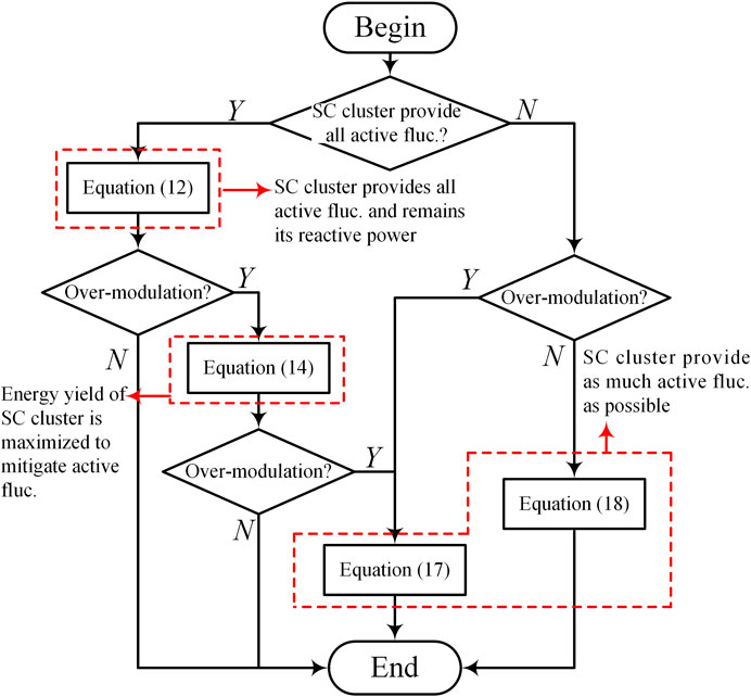
FIGURE 7. Flowchart of power distribution algorithm for power compensation mode.
When the active fluctuation is at a low level, SC clusters can eliminate the fluctuation and provide reactive power simultaneously. In this condition, the desired active and reactive power variations for SC cluster can be separately described as:
where ΔPc and ΔQc respectively represent the variations between the active and reactive power generated by SC cluster in Mode II and in rated condition. In addition, the power generation of SC cluster in rated condition can be calculated by rated parameters as (9), while the power generation of SC cluster in Mode II can be described as (10):
Note that (10) is equal to the sum of (8) and (9), the following equation can be obtained:
In accordance with (11), the d- and q-axis voltage references of SC cluster can be calculated by:
where Is is the amplitude of the output current. If using the SC cluster voltage references of (12) leads to over-modulation of the HESS, SCs should mitigate active power fluctuations preferentially, and their energy yield should be maximized. Hence, the SC cluster voltage references should meet the following equation:
where VSCΣmin represents the lower limit of the sum SC voltages in each phase. According to (13), the d- and q-axis of SC cluster voltage references can be calculated as follows:
When the SC cluster voltage reference calculated by (14) also leads to over-modulation, SC cluster voltage reference should be chosen at the extreme case that both SC and battery cluster are operating at their maximum modulation ratio as follows:
According to (15), the d- and q-axis of SC cluster voltage can be respectively calculated by:
In this condition, SC cluster voltage reference can be determined in accordance with active power fluctuation. When the active fluctuation is positive, the SC cluster voltage vector nearest to the output current will be chosen to inject active power into the grid. When the active fluctuation is negative, the SC cluster voltage vector farthest from the output current will be chosen to absorb active power from the grid. Thus, according to (16), the d- and q-axis of SC cluster voltage reference can be respectively described as:
When the active fluctuation exceeds the maximum power generation of SC cluster, SCs cannot provide all active fluctuation. In this condition, SC cluster should mitigate as much active fluctuation as possible; hence, SC cluster is desired to generate pure active power. Consequently, SC cluster voltage should be in phase with output current, and the SC cluster voltage can be calculated as follows:
According to the restriction of modulation ratio, SC can generate pure active power only when the output current reference meets (19); otherwise, they should be calculated according to (17).
Active Power Capacity of the HESS
In this section, the active power capacity of the HESS is analyzed to facilitate the design of the HESS. In the following analysis, dc voltages of SC and battery clusters are assumed to be determined. The analysis is executed in dq frame, and all switches, diodes, inductances, capacitors are assumed as ideal components. The voltage across the filter inductance is ignored to simplify the calculation. Details of the active power capacity in different modes are separately presented in the following subsections.
Active Power Capacity of SC Voltage Regulation Mode
SC voltage regulation mode is activated under rated power dispatch or when SC voltages reach their thresholds during active fluctuations. As SCs serve as STATCOMs in this mode, SC cluster voltage approximately has 90° phase shift with the output current. According to SC cluster voltage phasor diagram depicted in Figure 8, at point K and K’, the modulation ratio of both SC and battery cluster reaches their maximum, and consequently, the d-axis of output current reaches its extreme value. The extreme cases can be described as the following equation:
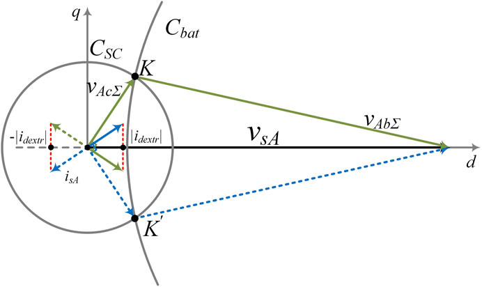
FIGURE 8. Phasor diagram of extreme id in SC voltage regulation mode.
Thus, the extreme value of id* can be derived from (20) as (21), and consequently, the extreme active power reference is given by (22).
Moreover, since that battery cluster generate all the active power demand in Mode I, the extreme active power generation of the HESS is also restricted by the discharge current of batteries. Subsequently, the extreme active power generation is described as (23) considering the maximum discharge current of batteries.
where Idis,max is the maximum discharge current of batteries.
Accordingly, the extreme active power output of the HESS in Mode I is equal to the minimum of those calculated by (22) and (23), which can be described as:
Thus, according to (24), the active power capacity of the HESS in Mode I is given by:
Active Power Capacity of Power Compensation Mode
Power compensation mode is activated under active fluctuations. It’s a temporary operation mode, which will be switched to Mode I mode compulsively when SC voltages reach their thresholds. According to the proposed power allocation strategy for power compensation mode, the extreme case appears when SC cluster merely generates active power and the insufficient active power are supplied by battery cluster. Hence, the active power generated by battery cluster is also restricted by the maximum discharge current of batteries as:
Consequently, the active power capacity of the HESS in Mode II is given by:
Simulation and Experimental Verification
Simulation Verification
To demonstrate the proposed control strategy and the theoretical analysis, a CMC-based star-connected battery-SC HESS rated at 380 V/15 kVA is simulated with MATLAB/Simulink. Each individual phase encompasses one battery cell and one SC cell. The detailed parameters are listed in Table 1. The simulation includes the test of current control and power allocation control separately.
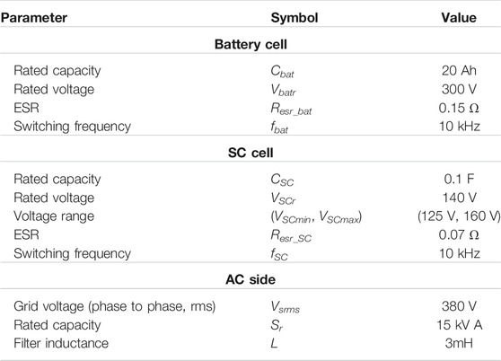
TABLE 1. Simulation and experiment parameter.
Figure 9A shows the simulation results of the grid voltage and output current of the HESS. Ten periods of the waveforms are cut out from the simulation result to verify the effectiveness of current control. It can be seen that output currents of all phases can stay constant with the same phase shift to their relative grid voltage. In addition, frequency spectrum of isA is depicted in Figure 9B, which shows the low total harmonics distortion (THD).
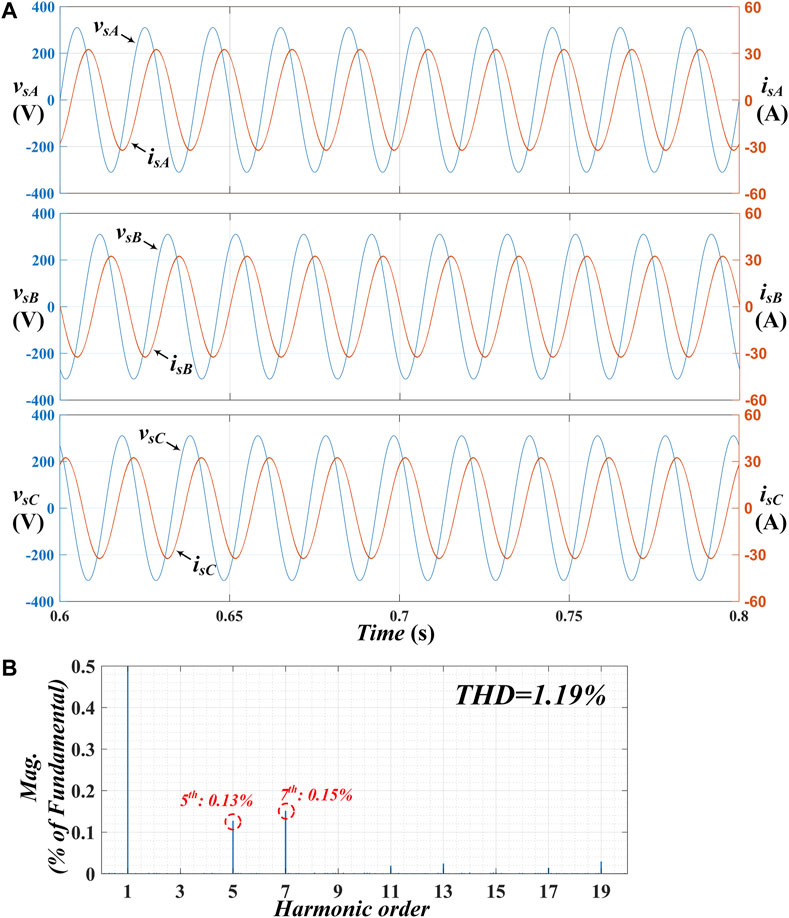
FIGURE 9. Simulation results of grid voltage and output current; (A) Three phase grid voltage and output current waveforms; (B) Frequency spectrum analysis of isA (cut out at 0.5%).
To verify the power allocation strategy for different modes, a series of test with six steps is executed on the same simulation model. Figures 10A,B presents the simulation results from 0.5 to 4.5 s, encompassing waveforms of SC voltages, and active power of phase A. The detailed description of the six-step simulation is shown as follows:
Step 1 (0 ∼ t1): HESS operates in Mode I, active power is merely generated by battery cells, and dc voltages of SCs are regulated at their rated value 140 V.
Step 2 (t1∼ t2): Positive active fluctuation appears, and consequently, HESS is switched to Mode II. By the proposed SC cluster voltage algorithm, SC cells generate active power and discharge.
Step 3 (t2∼ t3): Due to positive active fluctuation, SCs keep discharging, and at t2, SC voltages reach their lower threshold; subsequently, operation mode is switched to Mode I compulsively. Since that positive active fluctuation still exists during this period, dc voltages of SCs are regulated at the lower voltage threshold 125 V.
Step 4 (t3∼ t4): The active fluctuation changes into negative; consequently, Mode II is activated and SC cells absorb active power from the grid and keep charging.
Step 5 (t4∼ t5): SC voltages rise to their maximum operating voltage since that SCs keep charging. To protect SCs, the mode is switched to Mode I, and dc voltages of SCs are regulated at maximum operating voltage 160 V.
Step 6 (t5∼ t6): The active power command recovers to rated value at t5. The operation mode is still Mode I, nevertheless, the SC voltage reference varies to 140 V. According to Figure 10A, the new SC voltage reference can be accurately tracked by the proposed SC voltage regulation strategy.

FIGURE 10. Simulation verification for the proposed hierarchical control with two operation modes; (A) Waveforms of SC voltages; (B) Waveforms of active power in phase A; (C) Enlarged waveforms of active power at t1; (D) Enlarged waveforms of active power at t3.
In addition, Figures 10B,C presents the enlarged active power waveforms when active fluctuation changes. Figure 10B shows that before and after the positive active fluctuation appears at t1, active power generated by battery cluster nearly has no variation. It demonstrates that the proposed power allocation strategy for power compensation mode can merely use SC cell to mitigate active fluctuations. Meanwhile, Figure 10C presents the active power distribution at t3. Different from the case at t1, the active power absorbed by SC cluster is insufficient, and consequently, the active power generated by battery cluster drops as well. Hence, it can be drawn that battery cluster can effectively extend active power capacity for SC cluster by the proposed power allocation strategy.
The simulation results demonstrate that the CMC-based HESS can operate stably with high output quality and fast dynamics. The mode switching algorithm can effectively choose a suitable operation mode according to the EMS. In addition, the proposed power allocation strategy can mitigate arbitrary active fluctuation with SC cluster serving as main power compensation source and battery cluster generating the insufficient active power. Consequently, both the energy yield of SCs and batteries is maximized which can extend the power compensation range for the HESS.
Moreover, the proposed power allocation control is compared with the conventional individual phase control presented in (Wang et al., 2017; Zhang L et al., 2019). Figures 11A,B respectively depicts the power waveforms of the proposed allocation strategy in this paper and the conventional method. Using the proposed hierarchical power allocation control, both active and reactive power can return to steady state after about 0.15 s when the grid dispatch change at t. However, using the conventional method, the active power returns to steady state after 0.2 s and the reactive power returns to steady state after 0.3 s. The comparison results demonstrate that the proposed hierarchical power allocation control has better dynamic performance than conventional method since that the calculation is simplified and the dual-loop control is avoided by the hierarchical mechanism.
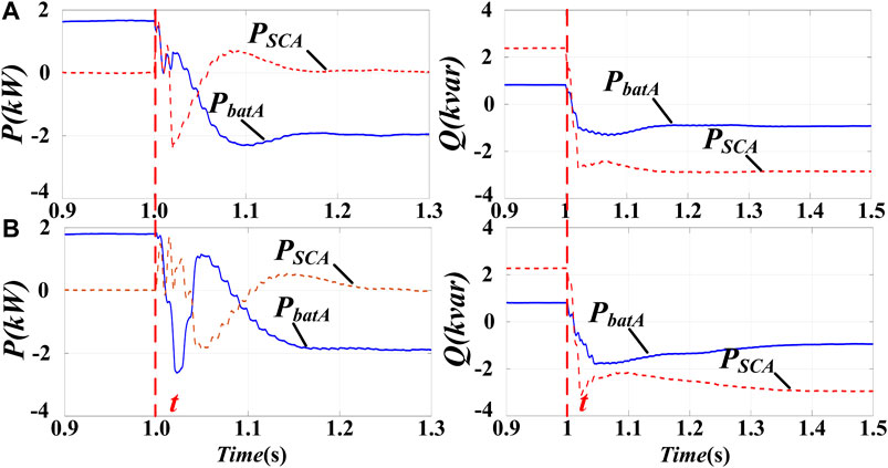
FIGURE 11. Comparison between the proposed hierarchical power control and the conventional individual phase control; (A) Power waveforms using the proposed control strategy; (B) Power waveforms using the conventional method.
Experimental Results
The experiment is conducted on a laboratorial 2 kV/100 kVar CMC-based STATCOM platform as shown in Figure 12. Four converter cells of each phase are employed in the experiment. Three of them are connected to 100 V dc power supplies to emulate battery cells. Another cell is connected to super-capacitor module to serve as SC cell. The proposed control strategy is implemented in DSP and CPLD co-controller, which can manage 24 cells at most by using 2 CPLDs to extend the output channels of DSP. The system parameters are similar to that in the simulation as presented in Table 1. The experimental results have been recorded to demonstrate the performance of the control strategy. Details of the experimental results are shown as follows.
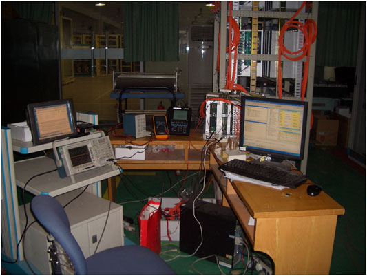
FIGURE 12. Laboratorial 2 kV/100 kVar CMC-based STATCOM platform.
Experiment for current control is shown in Figure 13. Figure 13A presents the phase relation of grid voltages and output currents. Limited by number of oscilloscope channels, Figure 13A merely depicts waveforms of phase A and B. CH1 and CH3 respectively show vsA and isA, while CH2 and CH4 show vsB and isB. According to the amplitude of output current and their phase shift to the corresponding grid voltage, the effectiveness of current control can be deduced. Figure 13B presents the output current of three phases simultaneously to demonstrate the interphase phase shift and stability of output currents. In addition, the waveform of isA is imported to MATLAB to analyze its harmonics distortion. Shown in its frequency spectrum, the low THD verifies the good performance of the proposed current control.
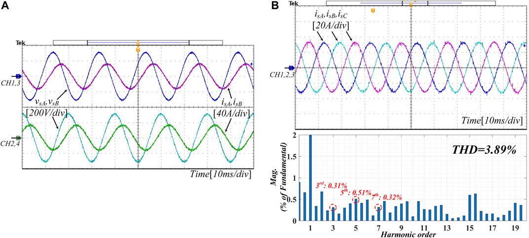
FIGURE 13. Experiment waveforms of grid voltage and output current; (A) Grid voltage and output current of phase A and B; (B) Three phase output current and frequency spectrum of isA (cut off at 2%).
By embedded power dispatch and mode switching program, the experiment for the switching of operation modes are executed as depicted in Figure 14. The power references for experiment are in accordance with that in simulation. In initial stage, with rated power reference, HESS operates in Mode I, and SC voltages are regulated at 140 V. At t1, the positive active fluctuation occurs, and consequently, Mode II is activated with SCs discharging. The discharge rate of SCs tends to be flat when SC voltages approach to their lower threshold, and finally regulated at 125 V. At t2, the embedded power dispatch generates negative active fluctuation, and SCs keeps charging till their voltage reach the maximum operating value. At t3, the active fluctuation recovers to zero, and VSCA, VSCB, VSCC go back to 140 V synchronously. In addition, the SC voltages of three phases shows good balance in the whole process.
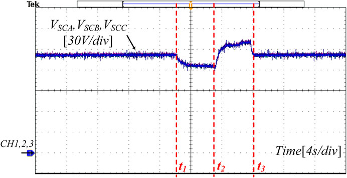
FIGURE 14. Waveforms of SC voltages during the whole experiment process.
The experimental results also verify the validation of the proposed method. The HESS can provide high quality and meet the grid dispatch with fast dynamics. Operation modes are switched flexibly according to the grid dispatch. while SCs can mitigate active fluctuation with good balance. Thus, long-term stable operation and short-term power compensation can be simultaneously achieved by the hierarchical power allocation strategy.
Conclusion
In this paper, hierarchical power allocation strategy is proposed for CMC-based star-connected battery-SC HESS. To solve the challenge caused by the synchronous ac current on the converter arms, the presented hierarchical control aims to achieve asymmetrical power coordination by distributing output voltage of SC and battery clusters. Comparing to conventional power allocation strategy for CMC-based HESS, hierarchical mechanism can reduce system complicity and achieve fast dynamics due to the following reasons: 1) control strategy is based on dq frame which avoids large amounts of vector calculation; 2) dual-loop controller is avoided since that the current control and power allocation is divided into layers. Correspondingly, EMS with two operation modes is implemented in the HESS to realize long-term stable operation and short-term power compensation simultaneously. With simplified operation modes, the mode switching algorithm can be easily achieved. According to the simulation and experimental verification, HESS using the proposed hierarchical control can meet the grid dispatch in the whole process and distribute power flexibly; moreover, it has better dynamic performance than the conventional method according to the comparison test.
Data Availability Statement
The raw data supporting the conclusion of this article will be made available by the authors, without undue reservation.
Author Contributions
All authors listed have made a substantial, direct and intellectual contribution to the work, and approved it for publication.
Funding
This study is supported by State Key Laboratory of Smart Grid Protection and Control (Grant: SGNR0000KJJS2007620).
Conflict of Interest
Author XW is employed by NR Electric Co., Ltd.
The remaining authors declare that the research was conducted in the absence of any commercial of financial relationships that could be construed as a potential conflict of interest. The authors declare that this study received funding from State Key Laboratory of Smart Grid Protection and Control. The funder had the following involvement with the study: The laboratorial platform was established in State Key Laboratory of Smart Grid Protection and Control using the received funding, and the funder was involved in the experimental test of the article.
Publisher’s Note
All claims expressed in this article are solely those of the authors and do not necessarily represent those of their affiliated organizations, or those of the publisher, the editors and the reviewers. Any product that may be evaluated in this article, or claim that may be made by its manufacturer, is not guaranteed or endorsed by the publisher.
References
Adam, G. P., Abdelsalam, I. A., Ahmed, K. H., and Williams, B. W. (2015). Hybrid Multilevel Converter with Cascaded H-Bridge Cells for HVDC Applications: Operating Principle and Scalability. IEEE Trans. Power Electron. 30 (1), 65–77. Jan. 2015. doi:10.1109/TPEL.2014.2303111
Akar, F., Tavlasoglu, Y., and Vural, B. (2017). An Energy Management Strategy for a Concept Battery/Ultracapacitor Electric Vehicle with Improved Battery Life. IEEE Trans. Transp. Electrific. 3 (1), 191–200. Mar. 2017. doi:10.1109/TTE.2016.2638640
Aneesh Kumar, A. S., Poddar, G., and Ganesan, P. (2015). Control Strategy to Naturally Balance Hybrid Converter for Variable-Speed Medium-Voltage Drive Applications. IEEE Trans. Ind. Electron. 62 (2), 866–876. Feb. 2015. doi:10.1109/TIE.2014.2341606
Chen, S., Friedrich, D., and Yu, Z. (2021). Optimal Sizing of a Grid Independent Renewable Heating System for Building Decarbonisation. Front. Energ. Res. 9, 746268. Aug. doi:10.3389/fenrg.2021.746268
Choi, M.-E., Lee, J.-S., and Seo, S.-W. (2014). Real-Time Optimization for Power Management Systems of a Battery/Supercapacitor Hybrid Energy Storage System in Electric Vehicles. IEEE Trans. Veh. Technol. 63 (8), 3600–3611. doi:10.1109/TVT.2014.2305593
Clerici, A., Tironi, E., and Castelli-Dezza, F. (2018). Multiport Converters and ESS on 3-kV DC Railway Lines: Case Study for Braking Energy Savings. IEEE Trans. Ind. Applicat. 54 (3), 2740–2750. May. doi:10.1109/TIA.2018.2792420
Feng, J., Liu, Z., Kong, J., Zhang, Y., Zhao, S., Dong, L., et al. (2019). Operating Mode and Coordinated Power Control for Photovoltaic Battery Hybrid System Using Cascaded Multilevel Inverter. IEEE Energ. Convers. Congress Exposition (Ecce) 2019, 4241–4248. Baltimore, MD, USA, Sep. doi:10.1109/ECCE.2019.8912230
Hargreaves, J. J., and Jones, R. A. (2020). Long Term Energy Storage in Highly Renewable Systems. Front. Energ. Res. 8, 219, Sep. doi:10.3389/fenrg.2020.00219
Jiang, W., Ren, K., Xue, S., Yang, C., and Xu, Z. (2021). Research on the Asymmetrical Multilevel Hybrid Energy Storage System Based on Hybrid Carrier Modulation. IEEE Trans. Ind. Electron. 68 (2), 1241–1251. Feb. 2021. doi:10.1109/TIE.2020.2967723
Jiang, W., Xue, S., Zhang, L., Xu, W., Yu, K., Chen, W., et al. (2018). Flexible Power Distribution Control in an Asymmetrical-Cascaded-Multilevel-Converter-Based Hybrid Energy Storage System. IEEE Trans. Ind. Electron. 65 (8), 6150–6159. Aug. doi:10.1109/TIE.2017.2787557
Jiang, W., Zhu, C., Yang, C., Zhang, L., Xue, S., and Chen, W. (2019). The Active Power Control of Cascaded Multilevel Converter Based Hybrid Energy Storage System. IEEE Trans. Power Electron. 34 (8), 8241–8253. Aug. doi:10.1109/TPEL.2018.2882450
Kavousi, A., Fathi, S. H., Milimonfared, J., and Soltani, M. N. (2018). Application of Boost Converter to Increase the Speed Range of Dual-Stator Winding Induction Generator in Wind Power Systems. IEEE Trans. Power Electron. 33 (11), 9599–9610. Nov. 2018. doi:10.1109/TPEL.2018.2797095
Kim, S.-H., Jang, Y.-H., and Kim, R.-Y. (2019). Modeling and Hierarchical Structure Based Model Predictive Control of Cascaded Flying Capacitor Bridge Multilevel Converter for Active Front-End Rectifier in Solid-State Transformer. IEEE Trans. Ind. Electron. 66 (8), 6560–6569. Aug. doi:10.1109/TIE.2018.2871789
Kim, S., Kwon, M., and Choi, S. (2018). Operation and Control Strategy of a New Hybrid ESS-UPS System. IEEE Trans. Power Electron. 33 (6), 4746–4755. Jun. 2018. doi:10.1109/TPEL.2017.2733019
Kollimalla, S. K., Mishra, M. K., and Narasamma, N. L. (2014). Design and Analysis of Novel Control Strategy for Battery and Supercapacitor Storage System. IEEE Trans. Sustain. Energ. 5 (4), 1137–1144. Oct. doi:10.1109/TSTE.2014.2336896
Koyama, Y., Nakazawa, Y., Mochikawa, H., Kuzumaki, A., Sano, K., and Okada, N. (2018). A Transformerless 6.6-kV STATCOM Based on a Hybrid Cascade Multilevel Converter Using SiC Devices. IEEE Trans. Power Electron. 33 (9), 7411–7423. –7423, Sep. 2018. doi:10.1109/TPEL.2017.2770143
Lahyani, A., Venet, P., Guermazi, A., and Troudi, A. (2013). Battery/Supercapacitors Combination in Uninterruptible Power Supply (UPS). IEEE Trans. Power Electron. 28 (4), 1509–1522. Apr. 2013. doi:10.1109/TPEL.2012.2210736
Lee, S. S., Sidorov, M., Idris, N. R. N., and Heng, Y. E. (2018). A Symmetrical Cascaded Compact-Module Multilevel Inverter (CCM-MLI) with Pulsewidth Modulation. IEEE Trans. Ind. Electron. 65 (6), 4631–4639. Jun. 2018. doi:10.1109/TIE.2017.2772209
Li, X., Wang, Z., and Yan, J. (2019). Prognostic Health Condition for Lithium Battery Using the Partial Incremental Capacity and Gaussian Process Regression. J. Power Sourc. 421, 56–67. May. doi:10.1016/j.jpowsour.2019.03.008
Li, X., Yuan, C., Li, X., and Wang, Z. (2020). State of Health Estimation for Li-Ion Battery Using Incremental Capacity Analysis and Gaussian Process Regression. Energy 190, 116467. Jan. 2020. doi:10.1016/j.energy.2019.116467
Li, X., Yuan, C., and Wang, Z. (2020). Multi-time-scale Framework for Prognostic Health Condition of Lithium Battery Using Modified Gaussian Process Regression and Nonlinear Regression. J. Power Sourc. 467, 228358. doi:10.1016/j.jpowsour.2020.228358
Liao, C.-Y., Lin, W.-S., Chen, Y.-M., and Chou, C.-Y. (2017). A PV Micro-inverter with PV Current Decoupling Strategy. IEEE Trans. Power Electron. 32 (8), 6544–6557. Aug. doi:10.1109/tpel.2016.2616371
Liming Liu, Liming., Hui Li, Hui., Yaosuo Xue, Yaosuo., and Wenxin Liu, Wenxin. (2015). Decoupled Active and Reactive Power Control for Large-Scale Grid-Connected Photovoltaic Systems Using Cascaded Modular Multilevel Converters. IEEE Trans. Power Electron. 30 (1), 176–187. Jan. doi:10.1109/tpel.2014.2304966
Liu, Z., Liu, B., Duan, S., and Kang, Y. (2012). A Novel DC Capacitor Voltage Balance Control Method for Cascade Multilevel STATCOM. IEEE Trans. Power Electron. 27 (1), 14–27. Jan. doi:10.1109/tpel.2010.2050337
Maharjan, L., Inoue, S., Akagi, H., and Asakura, J. (2009). State-of-Charge (SOC)-Balancing Control of a Battery Energy Storage System Based on a Cascade PWM Converter. IEEE Trans. Power Electron. 24 (6), 1628–1636. Jun. doi:10.1109/tpel.2009.2014868
Riboldi, L., Alves, E. F., Pilarczyk, M., Tedeschi, E., and Nord, L. O. (2020). Optimal Design of a Hybrid Energy System for the Supply of Clean and Stable Energy to Offshore Installations. Front. Energ. Res. 8, 607284. Dec. doi:10.3389/fenrg.2020.607284
Wang, K., Zhu, R., Wei, C., Liu, F., Wu, X., and Liserre, M. (2019). Cascaded Multilevel Converter Topology for Large-Scale Photovoltaic System with Balanced Operation. IEEE Trans. Ind. Electron. 66 (10), 7694–7705. Oct. doi:10.1109/TIE.2018.2885739
Wang, P., Liu, F., Zha, X., Zhu, F., Gong, J., and Feng, K. (2017). “A Segmented Power Distribution Control System Based on Hybrid Regenerative Cascaded Multilevel Converter,” in IEEE Applied Power Electronics Conference and Exposition, 724–728. Mar. 2017. APEC. doi:10.1109/APEC.2017.7930774
Wickramasinghe Abeywardana, D. B., Hredzak, B., and Agelidis, V. G. (2017). A Fixed-Frequency Sliding Mode Controller for a Boost-Inverter-Based Battery-Supercapacitor Hybrid Energy Storage System. IEEE Trans. Power Electron. 32 (1), 668–680. Jan. 2017. doi:10.1109/TPEL.2016.2527051
Xiao, J., Wang, P., and Setyawan, L. (2015). Hierarchical Control of Hybrid Energy Storage System in DC Microgrids. IEEE Trans. Ind. Electron. 62 (8), 4915–4924. Aug. doi:10.1109/TIE.2015.2400419
Yu, Y., Konstantinou, G., Hredzak, B., and Agelidis, V. G. (2016). Power Balance of Cascaded H-Bridge Multilevel Converters for Large-Scale Photovoltaic Integration. IEEE Trans. Power Electron. 31 (1), 292–303. Jan. doi:10.1109/TPEL.2015.2406315
Zha, X., Wang, P., Liu, F., Gong, J., and Zhu, F. (2017). Segmented Power Distribution Control System Based on Hybrid Cascaded Multilevel Converter with Parts of Energy Storage. IET Power Elect. 10 (15), 2076–2084. doi:10.1049/iet-pel.2016.0943
Zhang, L., Tang, Y., Yang, S., and Gao, F. (2019). Decoupled Power Control for a Modular-Multilevel-Converter-Based Hybrid AC-DC Grid Integrated with Hybrid Energy Storage. IEEE Trans. Ind. Electron. 66 (4), 2926–2934. Apr. doi:10.1109/TIE.2018.2842795
Zhang, Q., and Li, G. (2020). Experimental Study on a Semi-active Battery-Supercapacitor Hybrid Energy Storage System for Electric Vehicle Application. IEEE Trans. Power Electron. 35 (1), 1014–1021. Jan. 2020. doi:10.1109/TPEL.2019.2912425
Zhang, Y., Liu, Z., Kong, J., Feng, J., Zhao, S., Dong, L., Feng, M., and Hua, Q. (2019). “Power Distribution and Individual Phase Control of Asymmetrical Three-phase Cascaded Multilevel Hybrid Energy Storage System in Star Configuration,” in IEEE Energy Conversion Congress and Exposition (Baltimore, MD: ECCE), 6029–6034. doi:10.1109/ECCE.2019.8912752
Keywords: cascaded multilevel converters, hybrid energy storage system, hierarchical control, power allocation, multiple operation modes
Citation: Lu Y, Liu Z, Lyu J and Wei X (2021) Hierarchical Power Allocation Control for Star-Connected Hybrid Energy Storage System Using Cascaded Multilevel Converters. Front. Energy Res. 9:748508. doi: 10.3389/fenrg.2021.748508
Received: 28 July 2021; Accepted: 26 August 2021;
Published: 09 September 2021.
Edited by:
Xiaopeng Tang, Hong Kong University of Science and Technology, Hong Kong, SAR ChinaReviewed by:
Weihang Yan, National Renewable Energy Laboratory, United StatesBangyin Liu, Huazhong University of Science and Technology, China
Xiaoyu Li, Hebei University of Technology, China
Copyright © 2021 Lu, Liu, Lyu and Wei. This is an open-access article distributed under the terms of the Creative Commons Attribution License (CC BY). The use, distribution or reproduction in other forums is permitted, provided the original author(s) and the copyright owner(s) are credited and that the original publication in this journal is cited, in accordance with accepted academic practice. No use, distribution or reproduction is permitted which does not comply with these terms.
*Correspondence: Xing Wei, d2VpeEBucmVjLmNvbQ==