 Chenxi Li1
 Ji Li2*
- 1School of Engineering Science, University of Chinese Academy of Sciences, Beijing, China
- 2Laboratory of Advanced Thermal Management Technologies, School of Engineering Science, University of Chinese Academy of Sciences, Beijing, China
Data centers are becoming more powerful and more integrated with the continuous development of smart cities, which brings us more technological convenience, but also generates a large amount of waste heat. At present, the efficient and green cooling scheme is one of the key researches and development points to ensure the stable and safe operation of power electronic devices and achieve energy saving and consumption reduction. As a branch of the heat pipe, the pulsating heat pipe is one of most promising passive cooling techniques among many candidates for its unique advantages such as small size, simple and compact structure, and high heat dissipation efficiency, but its application in data centers just begins, and there are few reports on research and implementation. Based on the introduction of the basic structure, working mechanism and outstanding advantages of pulsating heat pipes, this paper reviews in detail the researches on the factors affecting its performance, so as to evaluate the possibility of using pulsating heat pipes in data centers. Finally, the latest application and development of pulsating heat pipes applied to heat dissipation of high-power CPUs are summarized, which can provide a guidance for subsequent research and engineering application.
Introduction
With the fast development of the Artificial Intelligence, internet communication, high performance computing, and big data analysis, especially in the context of the global fight against the COVID-19 epidemic in 2020, data center with a large amount of information processing, storage and computing is becoming a hot spot for a new round of investment and construction. In 2020, the growth rate of data center market in China exceeded 40%, and it had been continuously 30% in the past 3 years before 2020. However, the power consumption of the data center is a big problem. The power consumption rate, or PUE (Power Usage Effectiveness) (Grid, 2007), is often used to measure energy efficiency, which is the ratio of the total power consumption of the data center to the power consumption of IT equipment. The smaller the value, the smaller the power consumption and the higher the energy utilization rate. A survey report published a few days ago in “Science” magazine pointed out that the power consumption of data centers in 2018 was approximate 205 TWh, accounting for about 1% of all power consumption in the world, and the total power consumption still increase by 6% annually (Masanet et al., 2020). According to IDC (Internet Data Center), as of 2020, the number of racks deployed in global data centers is about 4.98 million, the total amount of data is about 50.52 ZB, and the power consumption is 299 TWh. It is estimated that by 2030, the global data center power consumption will reach 974 TWh, accounting for 8% of the total global power consumption (Anders, 2021). The power consumption of the data center is mainly composed of communication and network equipment, power supply and distribution systems, lighting systems and auxiliary equipment, as well as heat dissipation and cooling systems (Capozzoli and Primiceri, 2015). In the face of this “big heat producer”, nearly 40% of total power consumption will be used for heat dissipation and cooling. Therefore, to develop the new cooling technology, that is, the improvement of heat dissipation efficiency will be particularly conducive to the substantial increase in the overall efficiency of the data center.
Heat-generating devices in the server that is the basic component of a data center mainly include processors, storage units, voltage regulators, chips and power supply equipment. The current processor manufacturing process has entered the 7 nm era, and the TDP (Thermal Design Power) of a single CPU in high-power servers starts at 200 W. For example, the TDP of the AMD EPYC 7763 processor released in March 2021 has reached 280W, and the TDP of the intel Core i9-10990XE processor is as high as 380 W. In addition, considering that the Core i9-10990XE consumes about 600–700 W when all cores are pushed in, the actual power consumption of the Core i9-10990XE at the full Core 5.0 GHz will exceed 1000 W. Statistics show that since 1970, the performance and heat flux density of semiconductor transistors will double in an 18-months cycle, which is consistent with the predictions of Moore’s Law (Moore, 2002; Moore, 2006). For a data center with a small space and high heat flux density, the heat flux density can generally reach 60–100 W/cm2, and even reach 200 W/cm2 in special cases (Ebrahimi et al., 2014). The limit temperature of the chip is generally less than 70°C (or at most 85°C). On this basis, every 2°C increase in temperature will reduce its reliability by 10% (Haywood et al., 2015), which will bring huge challenges to the electronic information technology industry.
It can be seen that the development of high-efficiency cooling technology is of great significance, whether it is, to ensure the safe and efficient operation of electronic devices, or to save power in the data center and improve the level of energy utilization. According to different heat dissipation methods, it can be divided into active cooling and passive cooling. Among them, active cooling consists of forced air cooling, forced liquid cooling, refrigerating and thermoelectric cooling, etc., and passive cooling includes air or liquid natural convection, and phase change heat transfer (evaporation, condensation, boiling, and phase change materials).
The heat pipe is usually a closed pipe that is evacuated to a negative pressure and then filled with working fluids. Its structure consists of three parts along the axial direction, including evaporator, adiabatic zone and condenser. Through the vapor-liquid phase change, abundant heat can be transferred at both ends, and the pressure drop is small, which is isothermal. Extremely high effective thermal conductivity [even thousands of times higher than that of copper rods (El-Nasr and El-Haggar, 1996)], low effective thermal resistance and the feature of no moving parts make it a promising cooling method for electronic devices such as computers, telecommunications and satellite modules.
In the 1990s, Japanese scientist Akachi proposed the concept of pulsating heat pipe (PHP), which mainly relies on phase change and irregular oscillating motion to achieve high heat flux transfer (Akachi, 1990). Since there are no any moving parts, no additional energy is needed, which will make the PUE value infinitely close to 1, achieving extremely high energy efficiency. PHP has unique advantages in solving heat dissipation because of its compact structure and high heat transfer coefficient, which has attracted much attention from scholars (Zuo et al., 1999).
However, according to the author’s knowledge, there are few research reports on the application of PHPs in data center thermal management so far. Based on the introduction of the basic structure, working mechanism and outstanding advantages of PHPs, this paper reviews in detail the researches on the factors affecting its performance, so as to evaluate the heat dissipation potential of PHPs in data centers at rack, server and chip level scenarios. In the end, the latest application and development of PHPs applied to heat dissipation of high-power CPU are documented, which can provide guidance for subsequent academic research and industrial application.
Brief Introduction of Pulsating Heat Pipe
Pulsating heat pipe, abbreviated as PHP or OHP (Oscillating Heat Pipe), the traditional pulsating heat pipe is a serpentine structure formed by bending a capillary tube with a small inner diameter (generally 0.5–3 mm). Its structure is also divided into three parts: evaporator, adiabatic zone and condenser, which are the same as ordinary heat pipes. At present, PHPs can be roughly divided into two types: closed-loop and open-loop according to the structural design. Moreover, for the purpose of achieving the unidirectional flow of working fluids, closed-loop PHPs with check valves are introduced (Han et al., 2016). Figure 1 shows the three structures.
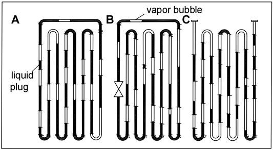
FIGURE 1. Different forms of pulsating heat pipes: (A) Closed-loop PHP; (B) closed-loop PHP with a check valve; (C) open-loop PHP.
Most studies have shown (Tong et al., 2001; Khandekar et al., 2003a; Groll and Khandekar, 2003) that the closed-loop PHPs can form a cycle, where the thermal performance is better than that of the open-loop. Therefore, this paper mainly discusses and analyzes the closed-loop PHPs. In addition, the directional flow of the working fluid in PHPs is enhanced by the check valve, and the increase in heating power will make this flow trend more obvious. The directional flow can promote more liquid to flow through the elbow of the evaporation section at a faster speed, reducing stagnation and improving the heat transfer performance of the PHPs (Thompson et al., 2011).
Operation Mechanism
Under the action of gravity and surface tension, the working fluid filled into the pre-evacuated serpentine capillary tube according to the prescribed filling ratio (FR) will be distributed in the tube at random intervals in two states of liquid plugs and vapor slugs. When the working fluid is gradually heated at the evaporator to meet the minimum superheat required for bubbles generation, the continuous growth and combination of bubbles will cut off the long liquid plug to generate new liquid plugs and vapor slugs. Continuous influx of new bubbles at the lower part of the liquid plug causes the pressure difference at both ends of the liquid plugs to increase, which pushes the high-temperature liquid plugs of the evaporator to move to the condenser. In the condenser, the high-temperature liquid plugs and vapor slugs dissipate heat, resulting in bubbles rupture, volume reduction and pressure reduction. Then, the movement of the liquid plugs will reduce the pressure of the evaporator and increase the pressure of the condenser. This reverse pressure difference and the pressure imbalance in the adjacent pipes make the working fluid oscillate irregularity between the two sections with different phase states and flow patterns.
Since the liquid plugs in each parallel pipe in the PHP are pushed to the condenser and squeeze each other, and the heating and cooling conditions are different, the liquid bubbles on the high-pressure side move at a relatively high speed from the evaporator to the condenser when the input heat load increases to a certain value. The sufficient inertia enables the liquid plugs to pass through the condenser and enter the next evaporator, and the flow patterns in PHP may transfer from oscillating flow to directional circulation flow sometimes. At this time, most of the liquid plugs and vapor slugs will frequently pass through the evaporator and the condenser to increase and decrease the temperature respectively, which means that the working fluid is more prone to phase change when flowing through the evaporator and the condenser, and the heat transfer efficiency is improved.
Startup Performance
Nucleation and denucleation are the two modes that enable PHPs to start. Denucleation initiated by liquid film evaporation is more likely to occur in heat pipes with low filling rate and relatively uniform vapor-liquid plug distribution, while the nucleation start is a necessary way for the PHP to enter full-scale oscillation, especially for a high filling rate.
The driving force of the denucleation start is mainly derived from the expansion/contraction of the vapor slugs in very small channels (Jian et al., 2012). When the driving force generated by the increase in the temperature difference between the cold and hot ends is greater than the flow resistance of the working fluid, the overall instability caused by the expansion/contraction of the vapor slugs will cause it to start up completely at an instant. At this time, the working fluid will move at a very high speed at the moment of startup, and the plug flow will quickly transform into the annular/semi-annular flow with latent heat and high heat transfer coefficient, making the temperature of the evaporator show a downward trend. Subsequently, the overall temperature of the PHP enters a stable pulsation stage, the annular/semi-annular flow disappears, and the working fluid basically returns to the plug flow state.
In addition to this startup, there is also a startup process induced by nucleation in the PHPs. When the amount of heating in the evaporation section meets the minimum superheat required for nucleation, that is, Eq. 1, some cavities on the inner surface of the capillary will form new microbubbles in the liquid plugs. As the surface temperature continues to increase, the vapor pressure also increases. The sudden increase in vapor pressure will cause a series of liquid plugs and vapor slugs to move quickly and continuously. If the heating flow level is low, the supercooled working fluid will take a long time to achieve nucleation boiling, and even cause the PHP to fail to start normally. Therefore, the higher the heat flow level, the shorter the waiting time, and the easier it is to trigger the PHPs.
Where
The nucleation sites can be increased by adding microstructures to the inner surface of the pipe, which will significantly improve the startup and operation improve of the PHP. With the cavity size increasing in a certain range, the minimum superheat and heat flux required for bubble formation decrease. In other words, it’s easy to start the PHP when the surface gets rougher. However, according to the theoretical analysis of Ma et al. (2015), the increase in surface roughness will bring greater frictional resistance to motion, which requires more heat to generate driving force. From the perspective of friction, the rough surface is not conducive to the oscillation movement in the PHP. Therefore, it is necessary to find a suitable roughness range for the best design.
Sensible Heat Versus Latent Heat
The heat absorbed or released by the working fluid when the temperature is continuously increased or decreased is called sensible heat, and there is no phase change at this time; while the latent heat is the heat absorbed or released from one phase to another in the case of isothermal and pressure. The amount of latent heat transfer with phase change is much greater than the amount of sensible heat transfer with temperature change. The heat transfer of the PHP is mainly composed of the latent heat transfer caused by the phase change of the thin liquid film (Spinato et al., 2016) and the sensible heat transfer caused by the liquid plugs oscillation.
Ma (2015) established the energy conservation equation of the vapor slugs and the momentum equation of the liquid plugs through the theoretical gas state equation and the first law of thermodynamics, and obtained a mass-spring-damping model that can be used to predict the oscillating motion of PHPs. The results show that heat transfer accounts for more than 90% of the total heat transfer. Senjaya and Inoue (2013) introduced a complex numerical model to explain the bubbles produced by nucleate boiling. According to their model, sensible heat transfer accounts for 74% of the total heat. A theoretical model established by Shafii et al. (2001) was used to simulate the vapor slugs and liquid plugs behavior in 2-turns closed-loop and open-loop PHPs. The results demonstrate that most of the heat transfer (95%) is in the form of sensible heat rather than latent heat of vaporization, and the latter is mainly the cause of the oscillating flow.
However, different scholars have reached conflicting conclusions regarding the main forms of heat transfer under different experimental or simulated conditions. A PHP numerical model established by Nikolayev (2011) shows that the latent heat transfer accounts for a large proportion, and the time average of the contribution of latent heat is 82% in the evaporator and 71% in the condenser. Jo et al. (2019) detected the fluid-solid interface temperature by an infrared camera, and heat flux density as well as the flow pattern changes at the corresponding temperature were observed. The results showed that the total contribution of latent heat transfer is estimated to be between 66 and 74%. Latent heat transfer not only causes oscillating flow, but also makes an important contribution to total heat transfer, but the sensible heat is a by-product of oscillating flow.
In addition, some literatures (Zhang and Faghri, 2008; Shafii et al., 2013) pointed out that the proportion of sensible/latent heat varies with the input heat load. Under low input heat load conditions, nucleate boiling does not occur, the main form of heat transfer is sensible heat. With the increase of heat flow density, bubbles are formed on the solid surface. The formation, growth and separation of bubbles increase liquid disturbance. PHP begins to have stable oscillating motion and even directional annular flow. The movement of the liquid plugs leaves a thin liquid film at the U-shaped bend in the evaporator. The evaporation of the thin liquid film makes the effect of latent heat particularly important. Spinato et al. (2016) found that compared to oscillating liquid plugs heat transfer and local nucleate boiling, thin liquid film evaporation is more important and is the main heat transfer method.
The reason for the diametrically opposite conclusions is related to the experimental settings of each scholar. Different pipe diameters, roughness, working fluids with different physical parameters and temperature operating ranges will all have an impact on the experimental conclusions. Sensible heat transfer needs to be realized by temperature difference and specific heat capacity. When a working fluid with a large specific heat capacity (such as water) is used and the heat load input is large, the sensible heat transfer will naturally become more significant. At the same time, a higher filling rate will also increase the number of liquid plugs used for pulsating motion, which will further increase the amount of sensible heat transfer. Sensible/latent heat are both heat transfer mechanisms of PHPs, but their respective proportions have not yet been fully understood. To understand the heat transfer mechanism of PHPs, further experimental analysis, numerical simulation and theoretical research are needed to be conducted.
Thermal Resistance
The indicators to measure the operating performance of the PHP usually include the temperature of evaporator, the temperature variation amplitude and frequency, and the thermal resistance. The calculation equation of thermal resistance can be obtained from Eq. 2. Where,
Maximum Heat Capacity Q max
The continuous input of heat load will gradually reduce the number of liquid plugs and increase the vapor slugs respectively. At a certain moment, the evaporation section of the capillary tube will be filled with vapor slugs, the higher pressure prevents the liquid from being recirculated and supplemented. At this time, the mass-spring-damping model that provides power for fluid movement disappears. The lower heat transfer coefficient of steam causes the heat transfer efficiency to drop, and the tube wall temperature rises sharply, reaching the heat transfer limit (i.e., the state of dry-out).
As shown in Figure 2, a liquid plug and two vapor slugs were taken as the research objects. In order to make the vapor slug penetrates the liquid plug, the total force acting on the liquid plug will be overcome by the momentum generated by the slugs, namely:
Where
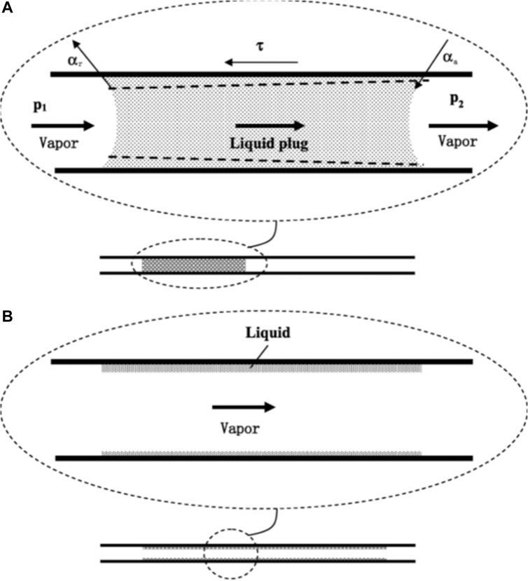
FIGURE 2. (A) The liquid plug and the vapor slugs coexist, and (B) the vapor slugs penetrate the liquid plug and fills the entire capillary tube (Yin et al., 2016).
Where
According to the model built by Yin et al. (2016), the maximum heat transfer capacity can be evaluated and calculated by:
Where L,
The factors affecting the heat transfer limit include the working fluid types, filling rate, flow rate, pressure, cross-sectional area, inclination angle, liquid film thickness, and wall temperature. Considering the above analysis, we can know that there must be enough working fluids for evaporation, otherwise it will be very easy to dry out. In addition, because nanoparticles increase the thermal conductivity and nucleate boiling point of the working fluids, and contribute to the rapid dissipation of heat, nanofluids can not only improve the startup performance and heat transfer performance of the PHP, but also improve the heat transfer limit of the PHP. Apart from this, some other means, such as mixing working fluids and self-wetting fluids, arranging the evaporator below the condenser and using gravity reflux, can also improve the heat transfer limit of the PHP and delay the phenomenon of dry-out.
Advantages of PHPs for High Power Electronics Cooling
1) The material is easy to obtain, the structure is simple and compact, the shape can be changed according to the application scenario, and the manufacturing cost is low (Kim and Kim, 2018).
2) No capillary structure is required, and without the capillary heat transfer limit and transport heat transfer limit of traditional heat pipes, PHPs can start and maintain the pulsating motion by converting the input heat load into the kinetic energy of the working fluids (Qu et al., 2018).
3) Since the working fluids pulsate in the same direction, the two-phase flow does not interfere with each other.
4) The thin liquid film formed by the movement of the liquid plug can significantly enhance the heat transfer of evaporation and condensation.
5) The combined effect of forced convection formed by oscillating motion and phase change heat transfer makes the heat transfer efficiency as high as 90%, while the heat transfer efficiency of traditional heat pipes are 60–70% (Zhang and Faghri, 2008; Leu and Wu, 2017).
Experimental Research on Influencing Factors
The heat transfer and hydraulic performance of PHPs are affected by various factors. Through the use of transparent quartz glass tubes with high-speed cameras, electrical capacitance tomography, neutron imaging, infrared imaging technology and other experimental visualization methods, domestic and foreign scholars have done a lot of researches on the influence of geometric parameters (Wang J. et al., 2015; He et al., 2020; Xie et al., 2020), physical parameters (Wang et al., 2019; Wang et al., 2020; Zhou et al., 2021) and operating parameters (Jian et al., 2012; Ahmad and Jung, 2020; Xie et al., 2020) of PHPs on its performance, and it is summarized as follows:
Geometric Parameters
Pipe Diameter
The appropriate choice of pipe diameter is directly related to whether PHPs can run smoothly. The design standard is determined by the Bond number:
The study found (Zhang and Faghri, 2008) that only when Bo ≤ 2, that is, when the gravity is less than the surface tension, stable vapor slugs and liquid plugs will be formed in PHPs. The smaller pipe diameter results in smaller liquid plugs amplitude, higher frequency, greater heat transfer per unit area, and higher thermal conductivity. But too small pipe diameter will bring higher viscous resistance, so the best pipe diameter range is (Qu et al., 2012):
Most of the literatures (Burban et al., 2013; Pachghare and Mahalle, 2014; Yang et al., 2017) use a pipe diameter of 2–3 mm. However, Rittidech et al. (2003) pointed out that for different working fluids, the heat transfer performance will vary with the pipe diameter and even the opposite effect is obtained.
Cross-Section
The cross-sectional shape of the pipe determines the flow path and flow pattern distribution of working fluids. Most current studies still use a circular cross-section, which has a small flow resistance (Jafarmadar et al., 2016; Fourgeaud et al., 2017). However, many scholars have explored the application of new cross-sections. Guo-Wei et al. (2012) designed and manufactured two kinds of flat plate PHPs with the structure of double-sided rectangular and triangular channel. Experimental data show that the two new type heat pipes have stable and good heat transfer characteristics, and the heat transfer performance of the triangular section heat pipe is better. Liu et al. (2007) proposed two special structures of PHPs. One type of PHP has a periodic change in pipe diameter, and the other has a thicker part of the tube wall than other parts of the tube. Through visualization experiments, it is found that the flow pattern of working fluids in the two PHPs with special structure is easier to form and maintain annular flow, and the possibility of directional circulation is greater. The liquid can return to the evaporator in time, and the heat transfer performance is improved. Chien K.-H. et al. (2012) and Tseng et al. (2014) found that compared with traditional parallel channels with equal cross-sections, parallel channels with varying inner diameters can introduce additional unbalanced capillary forces, so that PHPs can run successfully even at 0° inclination.
From the above research and analysis, we can see that the working fluid in the alternating cross-section or gradual cross-section channel will add an additional cyclic power due to the non-uniform structure on the basis of the original cyclic driving force, which increases the internal pressure disturbance and effectively drives the directional flow of the internal working fluid. The thermal performance of PHPs will indeed be improved to a certain extent, but it also increases manufacturing and maintenance costs accordingly. In practical applications, we must comprehensively weigh and make the best choice.
Hydrophilicity and Hydrophobicity of Tube Wall
The hydrophobicity of the condensation section of PHPs will reduce the fluid resistance, making the fluid of PHPs easier to move, and the pulsation amplitude is larger. But the hydrophobic surface results in higher thermal contact resistance, which hinders the heat transfer at the condensation section.
The evaporation section has a hydrophilic surface, which will cause the thin liquid films to form more easily. The evaporation of liquid films promotes the evaporation of the evaporator and heat transfer coefficient is higher. According to the surface energy minimization criterion (Srinivasan et al., 2015), the liquid film will rupture and disappear if the thickness of the liquid film is less than a certain value. Physically this means that, during the flow of a partially wetting fluid (θe equilibrium contact angle), the evaporation occurring at the thin-film region can be continuously replenished by the drainage of thin-film, due to the flow itself.
If the evaporation section is a hydrophobic surface, As the plug slides over the evaporation end, small droplets with large contact angles form on the surface, which tends to film boiling requiring a higher degree of superheat, and the hydrophobic layer increases the heat transfer resistance, making the heat transfer performance of PHPs worse.
In addition to this, studies on the mixing surface (hydrophilic in the evaporator and hydrophobic in the condenser) have shown that the unidirectional flow of working fluids in PHPs can improve its performance (Hao T. et al., 2014, Hao Tingting et al., 2014; Leu and Wu, 2017).
Length of Pipe and Each Section
To be sure, the heat exchange effect is best when all the heat in the evaporation section can be dissipated through the condensation section. Therefore, the length of the condensation section can be designed to be greater than the length of the evaporation section. Rahman et al. (2015) designed the evaporation section to 5 cm and the condensing section to 8 cm. Kim and Kim (2018) concluded that the greater the ratio of the evaporation section to the condensation section of the single-turn PHP, the shorter the startup process.
Number of Turns
More turns will increase the heat exchange area, enhance the pulsation of the working fluids, and weaken the influence of gravity, which is helpful for startup. However, too many turns will cause greater pressure loss and occupy a large space, which does not meet the needs of heat dissipation in limited space. Pouryoussefi and Zhang (2017) carried out a numerical simulation on a 4-turn PHP, and the results show that it will be better for PHP to run by increasing the number of turns. Studies (Cai et al., 2002; Khandekar et al., 2003b) have shown that there is a critical value for the number of turns that makes PHPs performance independent of the inclination angle. Yang et al. (2009) found PHPs can be started smoothly at any inclination angle when the turn number is 40, but this critical turn number may not be suitable for other PHPs devices.
Compatibility of Working Fluids for Different Casing Materials
In order to make PHPs operate safely and efficiently, the surface tension is an important factor for the physical properties of working fluids. However, different scholars have reached conflicting conclusions about whether higher or lower surface tension values are more beneficial to PHPs performance. The experimental results of Shafii et al. (2013) showed that larger surface tension will increase the critical value of the pipe diameter, and increasing the pipe diameter will reduce the flow resistance, which can improve heat transfer performance. On the contrary, Groll and Khandekar (2003) pointed out that a working fluid with a larger surface tension increases the friction force of the liquid plug movement, thereby increasing the flow pressure drop. Therefore, it is considered that a smaller surface tension is better.
In general, the working fluid needs to meet the following conditions:
1) Appropriate phase change latent heat. If the value is too small, it is easy to produce “bumping” phenomenon in the evaporator, and the heat transfer limit is too low. This problem can be improved by increasing the filling rate, but the bubble formation and growth rate is slowed down under the condition of high filling rate, in this case, phase change is difficult to occur. On the macro level, the pressure difference on both ends will be reduced, and the pulsating frequency and amplitude will be correspondingly reduced, resulting in the difficulty of startup;
2) Larger saturation pressure change value with saturation temperature (dP/dT) sat. This will cause the working fluid to produce larger pressure fluctuations under smaller temperature changes, which is conducive to oscillating heat transfer;
3) Smaller viscosity can reduce the shear stress along the tube wall, thereby reducing the pressure drop in the pipe, which will reduce the input heat load for maintaining the pulsating flow.
4) Larger thermal conductivity can not only reduce the response time of PHPs, but also maintain the temperature uniformity of PHPs.
5) Since the forced convection (sensible heat) of the working fluids determines the performance of PHPs more than the evaporation and condensation (latent heat), it is preferable to increase the heat transfer amount of sensible heat with a larger specific heat to achieve better performance.
6) Smaller fluid density can reduce the influence of gravity.
7) Consider the compatibility of the selected working fluids and the heat pipe material, that is, within the expected design life, the working fluid in the tube will not undergo significant chemical reaction or physical change with the tube shell, or there may be changes but not enough to affect the working performance of PHPs.
However, a working fluid cannot have all the best physical properties required, which can only be the result of a balance of these physical properties. At present, water, alcohols (methanol, ethanol, acetone), mixtures, nanofluids, etc., are mainly used as working fluids, which will be briefly introduced below.
The research of Rahman M. L. et al. (2015) showed that methanol as a working fluid is often used under high heat load input conditions, showing a better heat transfer performance than ethanol in a wide range of heat load, while ethanol is more suitable for lower heat input. Kim et al. (2017) found through experimental research that deionized water has higher saturation temperature and larger specific heat capacity than ethanol, so ethanol as a working fluid has better thermal performance under low thermal load input.
Yue et al. (2014) found that the performance of the PHP is the best when the mixing ratio of pure water and acetone is 13:1 under varying filling rates and heat input. Compared with pure working fluid, the reason why the performance of binary mixed fluid is better can be explained by the characteristics of phase change and intermolecular momentum exchange of mixed fluid.
The colloidal suspension in the nanoparticle base fluid is the basis of its thermophysical properties. The suspended nanoparticles reduce the thermal load required for the startup of PHPs, making PHPs easier to start, and improving its anti-drying ability (Karthikeyan et al., 2014). Lin et al. (2008) found that the average temperature difference and thermal resistance are significantly reduced when the working fluid is Ag/H2O nanofluid. Xing et al. (2017) studied the effect of hydrogenated MWNTs nanoparticles and pure water on the thermal performance of PHPs. Compared with pure water, the performance of PHPs was improved in a lower concentration of hydrogenated MWNTs nanofluid. When the concentration is higher, the lower the flow velocity in the tube caused by the higher viscosity and the weakening of the evaporation caused by the increased water absorption capacity will affect the heat transfer. Kang et al. (2017) studied the effect of iron oxide nanofluid on the performance of PHPs, and found that although the effect of magnetic nanoparticles is small under a higher heat input, the thermal performance of PHPs has been enhanced with a relatively low heat input.
Surfactant molecules regarded as a potential new working fluid are easily available and inexpensive, which can reduce thermal resistance and make PHPs more efficient. Wang X. H. et al. (2015) used different concentrations of sodium stearate surfactant solutions and deionized water solutions as working fluids to perform PHPs performance analysis. The results show that the surfactant solution is favorable to the operation of PHPs at the concentration of 10 ppm under all experimental input heat loads.
Since PHPs are usually made of copper, aluminum or silicon, Table 1 summarizes the types of working fluids that are compatible with copper/aluminum/Si PHPs between 0 and 100°C. In addition, Chi (1976) synthesized the physical parameters of working fluid and found a index that can be used to evaluate its poor performance, that is, Figure of Merit (FOM), which can be calculated by Eq. 9.
Where,
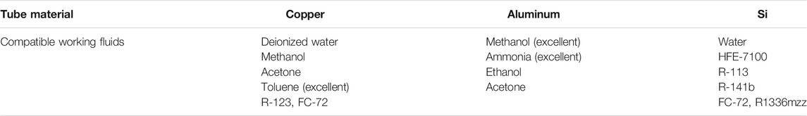
TABLE 1. Working fluid compatible with copper/aluminum/Si PHPs for electronics cooling.
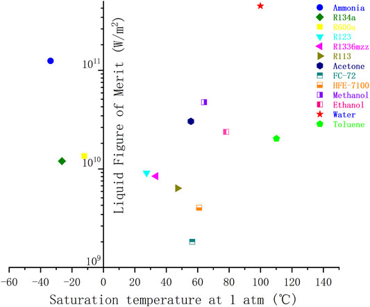
FIGURE 3. Figure of Merit for PHP working fluids.
Operating Parameters
Filling Rate
Filling rate refers to the ratio of the working fluid to the effective volume in the tube. If the filling rate is 0, the PHP becomes a pure heat conduction mode with high thermal resistance; if the filling rate is 1, the tube is completely full of the working fluid, resulting in a single-phase thermosyphon operation. Experimental studies have shown that (Shafii et al., 2001; Vassilev et al., 2007), when the filling rate is 0.2–0.8, a series of liquid plugs and vapor slugs in the PHP can be formed to ensure normal pulsating operation. Although statistics show that the optimal filling rate range is 0.35–0.65 (Han et al., 2016), the optimal filling rate is affected by other factors such as the physical properties of the working fluid, the inclination angle, the pipe diameter, and the input heat load, which cannot be uniformly defined.
Rahman et al. (2015b) studied the effect of open-loop PHP performance at different filling rates using deionized water and acetone as working fluids, and found that the performance reaches the best when the filling rate of acetone and water is 0.7 and 0.5 respectively. Verma et al. (2013) concluded that the optimal filling rates of deionized water and methanol are 0.5 and 0.4, respectively, and methanol has a shorter startup time and a lower startup temperature. Shi and Pan (2017) found that when the filling rate was 0.35–0.7, the performance of the PHP was better, and the optimal filling rate changed with the change of the input heat load. When the heat load is low, the best filling rate is low. This is because there are more vapor slugs and less liquid plugs formed in the tube, and the smaller driving force can start the PHP. With the increase of heating power, the optimal filling rate is also rising. However, too high filling rate will lead to fewer vapor slugs and more liquid plugs, which requires a larger thermal driving force and will cause the thermal resistance to increase.
Heat Input
The temperature curve of the evaporating section of PHPs changes from rising to a sudden decrease, and then to a continuous oscillation state, marking the successful startup of PHPs (Hu and Li, 2011). The thermal load corresponding to the turning point is the minimum thermal load required for starting (Hu and Li, 2011). The study of Jiansheng et al. (2016) found that the startup time of PHPs decreased with the increase of heating power, and this was verified in Patel and Mehta (2017) on the startup mechanism of PHPs.
During operation, the thermal resistance of PHPs decrease as the heating power increase (Hu and Jia, 2011). The input heat load also has an effect on the flow patterns. Khanderkar et al. (2003a) found in the visualization experiment that the flow patterns of the working fluid in the tube changes mainly as follows: bubbly flow, plug flow, jet flow, semi-annular flow (the evaporation section is mainly annular flow, and the condensation section is mainly plug flow).
Inclination Angle
The inclination angle refers to the angle value of the PHP with respect to the horizontal plane, and different inclination angles can achieve different thermal performance by changing the degree of gravity’s influence on the working fluid in the pipe.
For different working fluids and different filling rates, the best inclination angle is different. The experimental study conducted by Yang et al. (2008) showed that the 2 mm closed-loop PHP has the best thermal performance when the inclination angle is 90°, but the thermal performance will no longer be related to the inclination angle when the pipe diameter is reduced to 1 mm. Qu and Ma (2007) believe that when the inclination angle is 60°, the best performance can be obtained. At this time, the PHP deviates from the vertical position, and the shape of the bubble is asymmetrical along the pipe axis to form a convex portion, which accelerates the movement of the bubble. The research results of Saha et al. (2012) on an open-loop PHP filled with different working fluids show that the best inclination angles when water and methanol are used as working fluids are 90° and 0°, respectively.
Generally speaking, when the PHP is in the vertical state (that is, the evaporation section is located below the condensation section), gravity will help the condensed liquid return to the evaporation section, and the thermal performance of the PHP is the best (Chien K. et al., 2012; Paudel and Michna, 2014). In addition, after research and investigation, it is found that a sufficient number of turns and a sufficiently small pipe diameter will weaken the influence of the inclination angle on the operating performance of the pulsating heat pipe.
From the above analysis, we know that there are many factors affecting the thermal and hydraulic performance of PHPs, which are intricate. The critical research results of many scholars on its influencing factors are summarized in Table 2. Some common conclusions can be referred when designing a PHP cooler for high power electronic chips, e.g., the higher number of turns will aid in high heat load dissipation and tilt angle insensitivity; self-rewetting fluid is preferred; the optimal charging ratio is around 40–50%; the hydraulic diameter of tube commonly selected is around 1∼2 mm, et al.
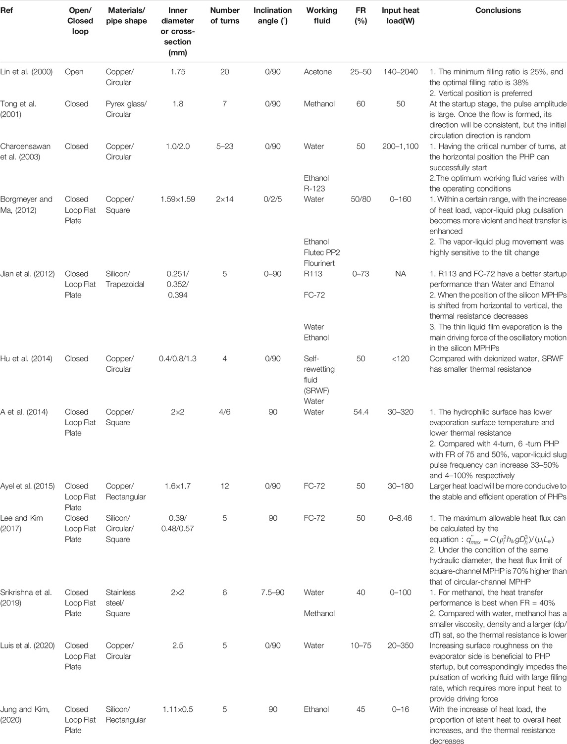
TABLE 2. Summary of experimental investigations on factors affecting the performance of PHPs.
Application of Pulsating Heat Pipe in Data Center
According to the difference of thermal management forms, the heat dissipation of the data center can be divided into five levels: room level, plenum level, rack level, server level, and chip level (Khalaj and Halgamuge, 2017). So far, the implementation of PHP coolers in data centers is very few.
Rack Level Cooling System
The rack level cooling system can realize the direct cooling of the IT equipment in the rack, and determine the amount of cold air by changing the fan speed and adjusting the location of the server to optimize the flow channel. A novel server rack heat dissipation structure based on PHPs was proposed by Chao et al. (2017), as shown in Figures 4A,B. In the research, the air inside and outside the rack is separated, and heat exchange is performed through a flat plate PHP as the back cover of the rack. Numerical simulation studies show that the CPU temperature is negatively correlated with heating power and axial fan pressure, and positively correlated with cooling air temperature. When the temperature of the 16 CPUs in the rack does not exceed 60°C, the maximum consumed power is 1380 W, as shown in Figure 4C.
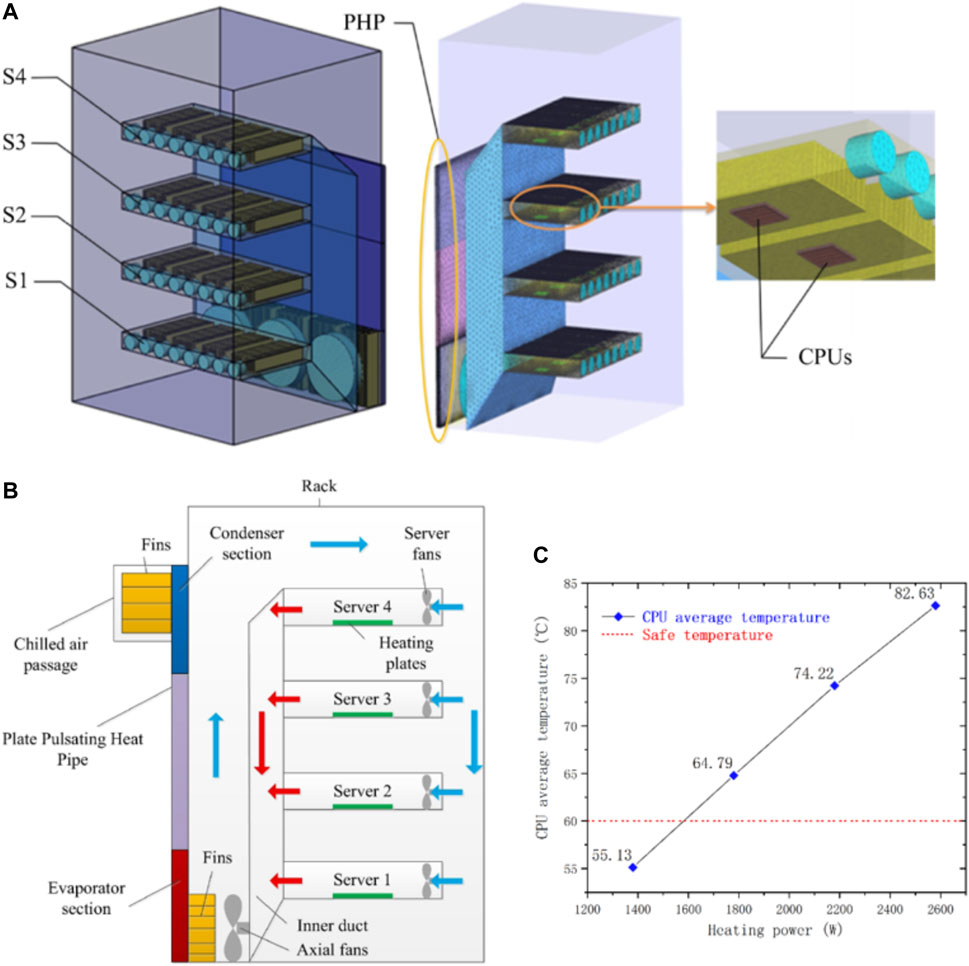
FIGURE 4. (A) The overall view and (B) internal view of the enclosed rack heat dissipation system based on PHP, and (C) the CPU temperature variation under different rack heat loads (Chao et al., 2017).
At the same time, similarly, Daraghmeh and Wang (2017) conducted experiments on a PHP radiator and a traditional thermal thermosyphon radiator (Figure 5) under the same conditions. The results show that the PHP-based radiator can reduce the junction temperature by 4–5°C compared with the traditional thermal thermosyphon radiator, which will help heat dissipation inside the rack.
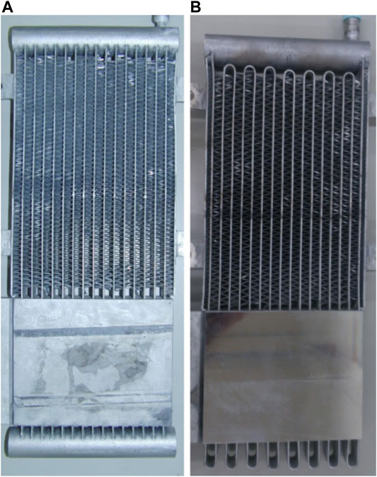
FIGURE 5. Schematic diagram of (A) thermosyphon heat exchanger and (B) pulsating heat pipe heat exchanger (Daraghmeh and Wang, 2017).
Server Level Cooling System
Servers are an important component of data centers, but they are also the main power consumers. On the one hand, fans can be used to adjust the airflow through the server to improve heat dissipation; on the other hand, on the information and communication equipment side, intelligently activating certain servers and setting other servers into sleep mode can help minimize server power consumption (Sakanova et al., 2019).
At present, 1U server mainly relies on metal fin heat sink and DC fan for heat dissipation. With the gradual development of heat dissipation technology in recent years, more compact structure and more efficient Vapor Chamber (VC) have been applied to server (Figure 6A). However, the mass of the VC integrated with metal heat sink is too high (1.198 kg), which is easy to cause high stress to the server CPU. Therefore, we designed a PHP-based aluminum radiator (Figure 6B), whose mass is reduced to 0.875 kg compared with the VC. The research on its heat transfer performance will be further elaborated in the subsequent articles.
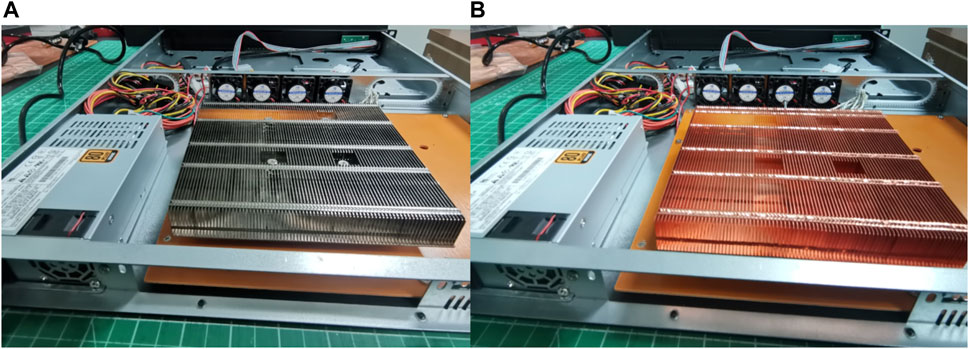
FIGURE 6. Heat sink of (A) commercial VC-based and (B) our PHP-based radiator for 1U server heat dissipation.
It should be noted that presently the immersion boiling is an emerging method attracting more attention and interest in China for server level cooling or even rack level cooling. However, it is out of the scope of this review.
Chip Level Cooling System
In terms of communication, dynamic voltage and frequency adjustment can be used to achieve chip energy saving and consumption reduction. In terms of heat dissipation, high thermal conductivity interface materials and other advanced thermal management methods can be used for heat dissipation.
Katoh et al. (2004) shows a practical industrial product based on pulsating heat pipe applied to heat dissipation of high heat flux computer CPU. Compared with the heat sink of copper block, the mass and thermal resistance are reduced by 40 and 45%, respectively. When the air flow rate is 1.24 m3/min and the heating power is 300 W, the thermal resistance is about 0.16 K/W, with efficient heat dissipation capacity.
Miyazaki (2005) designed straight and finned flexible PHPs to study PC CPU heat dissipation. The results show that a straight PHP with a capillary diameter of 1 mm and a number of turns of 12 has better performance. Under a maximum thermal load of 100 W, its thermal resistance is nearly 0.28 K/W, which can keep the temperature of the CPU thermal simulator at about 75°C level.
Tseng et al. (2018) proposed a three-dimensional structure PHP module suitable for high heat flux chips. When the heating power changes from 100 to 1000 W, the junction temperature changes from 38.87°C to 83.19°C, and the thermal resistance decreases from 0.148 to 0.0595 K/W. The heat transfer effect is better, which can be used for heat dissipation of high-power devices.
A PHP with a size of 37.5 mm × 75 mm × 3 mm is proposed in the literature (Boswell et al., 2018), as shown in Figure 7, the heating chip with an area of 0.5 cm2 is placed in the center of the pulsating heat pipe. The designed PHP thermal resistance is 0.2°C/W in the case of horizontal placement, which can meet the heat dissipation requirements of 1250 W/cm2 chips.
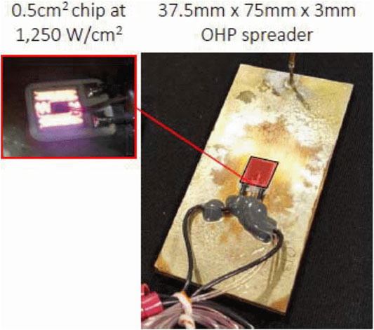
FIGURE 7. Chip cooling scheme based on pulsating heat pipe (Boswell et al., 2018).
A vertical PHP radiator for high heat flux CPU was proposed by Xiahou et al. (2019), as shown in Figure 8. It consists of a porous structure with a planar evaporating end and five condensation ends, and is 98 mm × 60 mm × 52 mm in size. The effects of filling rate, input power and wind speed on the startup performance and heat transfer performance of the vertical radiator are experimentally studied, and compared with aluminum finned radiators. Figure 9 depicts that the heat source temperature of the aluminum finned radiator is higher than the limited temperature of CPU (70°C), reaching 81.6°C when the input power is 80 W. While the heat source temperature value of the vertical radiator is 64.3°C, and the temperature distribution is more uniform, showing excellent heat dissipation performance.
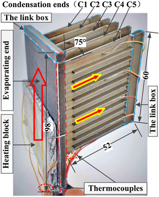
FIGURE 8. Schematic diagram of the novel vertical pulsating heat pipe radiator (Xiahou et al., 2019).
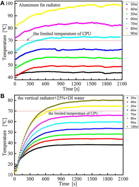
FIGURE 9. Temperature change of (A) the aluminum fin radiator, and (B) the novel vertical pulsating heat pipe radiator under different input power (Xiahou et al., 2019).
Shang et al. (2021) developed a PHP-based CPU cooler and carried out experimental research on it, as shown in Figure 10. The conclusion shows that when the cooling wind speed is 0.3 m/s, the startup time is the shortest, the startup temperature is the lowest (only 34.0°C), and the startup performance reaches the best state. The temperature uniformity of the PHP-based CPU cooler becomes better as the cooling wind speed increases. Compared with the maximum thermal resistance (1.36 K/W) at 0 m/s, the minimum average thermal resistance is 0.51 K/W at a wind speed of 0.7 m/s, and the maximum average heat source temperature is 53°C under 55 W power input, the details are shown in Figure 11.
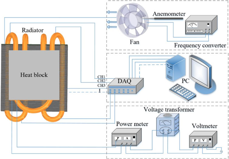
FIGURE 10. Schematic diagram of a CPU cooler based on PHP (Shang et al., 2021).
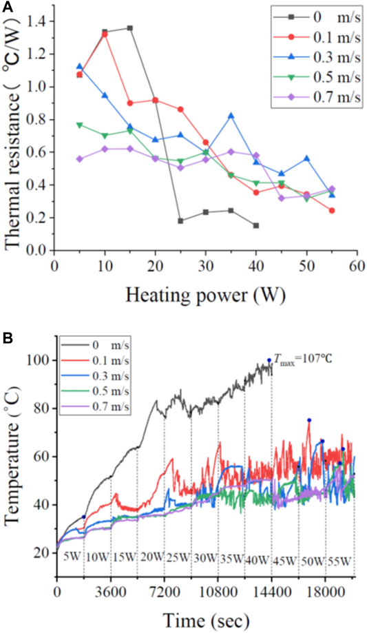
FIGURE 11. (A) Thermal resistance and (B) average temperature in the evaporation section with different wind speeds for the PHP CPU cooler (Shang et al., 2021).
Although PHP has been studied for several decades, it is mostly about the basic research on the factors affecting its startup performance and heat transfer performance, and has few practical applications in commercial cooling systems. Table 3 summarizes the researches on heat dissipation of CPU and high-power devices based on PHPs, and the total thermal resistance variations with input powers from different researches are plotted in Figure 12, which is also compared with the required thermal resistance for CPU cooling (red solid line). Compared with the traditional heat pipe, the coreless design of PHP greatly reduces the capital cost of the manufacturing process, and the self-excited oscillation pulsation makes the heat transfer performance higher and the heat transfer distance longer, which has great application potential in the high-power data center.
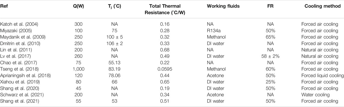
TABLE 3. Summary of heat dissipation of high-power chips based on PHPs.
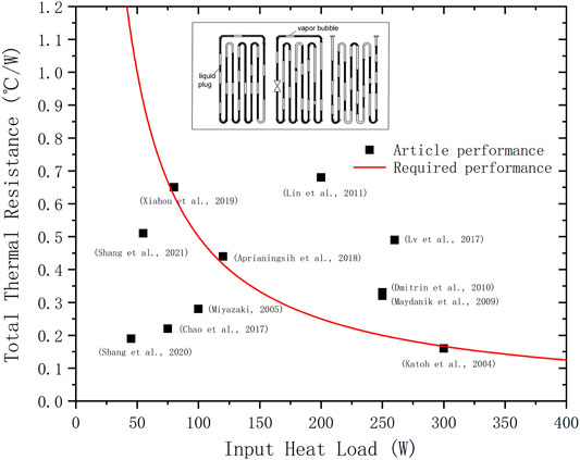
FIGURE 12. Summary of the total thermal resistance of PHP cooler from different researches.
Perspective and Conclusions
The data center market is getting bigger and bigger, and with huge energy consumption. The improvement of computer hardware performance makes the heat flux increase sharply. The total power per server can reach 300–800 W, and the power of a single rack can reach 20–30 KW. The efficient use of energy is the core issue of data centers, and the only way to achieve a low-carbon, environmentally friendly and sustainable society. There are currently five levels used to solve the heat dissipation problem of the data center: room level, plenum level, rack level, server level, and chip level. The heat dissipation means include forced air cooling, indirect liquid cooling (microchannel, heat pipe), direct liquid cooling (pool immersion boiling, jet cooling, spray cooling), refrigerating and thermoelectric cooling, phase change materials, etc.
Although great progress has been made in high-power chips cooling, there are still some difficult problems in the data center, such as:
1) For air cooling, the mixing of hot and cold air flow and whole room cooling will cause waste of cold capacity, low cooling efficiency, and uneven temperature distribution, which may easily form local hot spots inside the cabinet, causing server downtime or even damage;
2) For liquid cooling, it is mainly divided into direct liquid cooling and indirect liquid cooling. However, the liquid cooling system is too complicated, and has the risk of working fluid leakage. Meanwhile, liquid cooling faces the problem of precise control of sensitively responding to changes in the heat generated by the cabinet and timely adjusting the cooling capacity and flow.
3) For thermoelectric refrigeration, the refrigeration efficiency is low (COP is generally 0.1–0.4). The hot end overheating leads to secondary heat dissipation difficulties, the cold end undercooling leads to CPU chip surface condensation affects its performance and life, and the manufacturing cost is too high, which also restricts the large-scale application of thermoelectric refrigeration technology.
Based on the working principle, influencing factors and significant advantages of pulsating heat pipes compared with other heat dissipation ways, the application of pulsating heat pipes in high-power server CPUs is summarized in this paper. Pulsating heat pipes can be used in racks and lower levels to eliminate local hot spots and uneven air distribution in the data centers, showing excellent heat dissipation performance. Although pulsating heat pipes has not been widely used in the data centers, its combined cooling methods with liquid cooling and air cooling has a good prospect in the application of high heat flux data centers, which is a practical cooling scheme.
Great achievements have been made in the research and development of pulsating heat pipes, but there are still many urgent problems to be solved and further exploration is needed, which are summarized as follows:
1) Operating mechanism. The operating mechanism in the PHPs is relatively complicated, and the degree of understanding of it is still insufficient. Where, the chaotic behavior characteristics of PHPs, the coupling effect of fluid mechanics and thermodynamic characteristics, and the mechanism of heat and mass transfer between vapor slugs and liquid plugs need to be further studied.
2) Influencing factors. Many research literatures only consider the impact of a single variable on a single performance, and the value is discrete, but in actual operation, the performance of PHPs is coupled with each other, and the influencing factors are also mutually coupled and continuous, various parameters need to be optimized to improve its heat transfer performance.
3) Theory and numerical simulation. The established mathematical and physical models have made many assumptions and simplifications, so that the calculated results are quite different from the actual results. In the future research, the ignored factors should be gradually considered.
4) Engineering applications. The current mainstream heat dissipation method in data centers is still air cooling and liquid cooling, and the application of heat pipes is still less. Moreover, the mature commercial system of PHPs has not been fully established, and the lack of theoretical guidance in the practical application process cannot ensure the safety and stability of PHPs.
Author Contributions
CL: Investigation, formal analysis, writing original draft. JL: Conceptualization, writing review and editing.
Funding
This work is supported by National Natural Science Foundation of China (Project No. 51776195).
Conflict of Interest
The authors declare that the research was conducted in the absence of any commercial or financial relationships that could be construed as a potential conflict of interest.
Publisher’s Note
All claims expressed in this article are solely those of the authors and do not necessarily represent those of their affiliated organizations, or those of the publisher, the editors and the reviewers. Any product that may be evaluated in this article, or claim that may be made by its manufacturer, is not guaranteed or endorsed by the publisher.
References
Ahmad, H., and Jung, S. Y. (2020). Effect of Active and Passive Cooling on the Thermo-Hydrodynamic Behaviors of the Closed-Loop Pulsating Heat Pipes. Int. J. Heat Mass Transfer 156, 119814. doi:10.1016/j.ijheatmasstransfer.2020.119814
Anders, . S. (2021). Estimated Electricity Consumption of Global Data Centres 2020-2030 [Online]. Available: http://data.chinabaogao.com/it/2021/052K44K62021.html [Accessed].
Aprianingsih, N., Winarta, A., Ariantara, B., Putra, N., Kusrini, E., Juwono, F. H., et al. (2018). Thermal Performance of Pulsating Heat Pipe on Electric Motor as Cooling Application. E3S Web of Conferences 67. doi:10.1051/e3sconf/20186703035
Borgmeyer, B., and Ma, H. (2012). Experimental Investigation of Oscillating Motions in a Flat Plate Pulsating Heat Pipe. J. Thermophys. Heat Transfer 21 (2), 405–409. doi:10.2514/1.23263
Boswell, J., Wilson, C., Pounds, D., and Drolen, B. (2018). “Recent Advances in Oscillating Heat Pipes for Passive Electronics thermal Management,” in Thermal Measurement, Modeling and Management Symposium.
Burban, G., Ayel, V., Alexandre, A., Lagonotte, P., Bertin, Y., and Romestant, C. (2013). Experimental Investigation of a Pulsating Heat Pipe for Hybrid Vehicle Applications. Appl. Therm. Eng. 50 (1), 94–103. doi:10.1016/j.applthermaleng.2012.05.037
Cai, Q., Chen, R. L., and Chen, C. L. (2002). “An Investigation of Evaporation, Boiling, and Heat Transport Performance in Pulstating Heat Pipe,” in ASME 2002 International Mechanical Engineering Congress and Exposition.
Capozzoli, A., and Primiceri, G. (2015). Cooling Systems in Data Centers: State of Art and Emerging Technologies. Energ. Proced. 83, 484–493. doi:10.1016/j.egypro.2015.12.168
Chao, D., Li, J., and Lu, Q. (2017). Investigation on thermal Design of a Rack with the Pulsating Heat Pipe for Cooling CPUs. Appl. Therm. Eng. 110, 390–398. doi:10.1016/j.applthermaleng.2016.08.187
Chi, S. W. (1976). Heat Pipe Theory and Practice. Washington, D.C.New York: Hemisphere Publishing Corp.McGraw-Hill Book Co., 256.
Chien, K.-H., Lin, Y.-T., Chen, Y.-R., Yang, K.-S., and Wang, C.-C. (2012b). A Novel Design of Pulsating Heat Pipe with Fewer Turns Applicable to All Orientations. Int. J. Heat Mass Transfer 55 (21–22), 5722–5728. doi:10.1016/j.ijheatmasstransfer.2012.05.068
Chien, K. H., Lin, Y. T., Chen, Y. R., Yang, K. S., and Wang, C. C. (2012a). A Novel Design of Pulsating Heat Pipe with Fewer Turns Applicable to All Orientations. Int. J. Heat Mass Transfer 55 (21–22), 5722–5728. doi:10.1016/j.ijheatmasstransfer.2012.05.068
Daraghmeh, H. M., and Wang, C.-C. (2017). A Review of Current Status of Free Cooling in Datacenters. Appl. Therm. Eng. 114, 1224–1239. doi:10.1016/j.applthermaleng.2016.10.093
Dmitrin, V. I., Maidanik, Y. F., and Pastukhov, V. G. (2010). Development and Investigation of Compact Cooler Using a Pulsating Heat Pipe. High Temp 48 (4), 565–571. doi:10.1134/s0018151x10040140
Ebrahimi, K., Jones, G. F., and Fleischer, A. S. (2014). A Review of Data center Cooling Technology, Operating Conditions and the Corresponding Low-Grade Waste Heat Recovery Opportunities. Renew. Sust. Energ. Rev. 31 (2), 622–638. doi:10.1016/j.rser.2013.12.007
El-Nasr, A. A., and El-Haggar, S. M. (1996). Effective thermal Conductivity of Heat Pipes. Heat Mass. Transfer 32 (1), 97–101. doi:10.1007/s002310050097
Fourgeaud, L., Nikolayev, V. S., Ercolani, E., Duplat, J., and Gully, P. (2017). In Situ investigation of Liquid Films in Pulsating Heat Pipe. Appl. Therm. Eng. 126, 1023–1028. doi:10.1016/j.applthermaleng.2017.01.064
Groll, M., and Khandekar, S. (2003). “Pulsating Heat Pipes: Progress and Prospects,” in Energy and the Environment - Proceedings of the International Conference on Energy and the Environment.
Guo-Wei, X., Yang, C. Y., and Chen, L. L. (2012). Journal of Central South University. (ence and Technology).Heat Transfer Performance of Flat Plate Pulsating Heat Pipe with Double Sides Rectangular or Triangular Channel
Habibi Khalaj, A., and Halgamuge, S. K. (2017). A Review on Efficient thermal Management of Air- and Liquid-Cooled Data Centers: From Chip to the Cooling System. Appl. Energ. 205 (Nov.1), 1165–1188. doi:10.1016/j.apenergy.2017.08.037
Han, X., Wang, X., Zheng, H., Xu, X., and Chen, G. (2016). Review of the Development of Pulsating Heat Pipe for Heat Dissipation. Renew. Sust. Energ. Rev. 59 (Jun), 692–709. doi:10.1016/j.rser.2015.12.350
Hao, T., Ma, X., Lan, Z., Li, N., Zhao, Y., and Ma, H. (2014b). Effects of Hydrophilic Surface on Heat Transfer Performance and Oscillating Motion for an Oscillating Heat Pipe - ScienceDirect. Int. J. Heat Mass Transfer 72 (5), 50–65. doi:10.1016/j.ijheatmasstransfer.2014.01.007
Hao, T., Ma, X., Lan, Z., Li, N., and Zhao, Y. (2014a). Effects of Superhydrophobic and Superhydrophilic Surfaces on Heat Transfer and Oscillating Motion of an Oscillating Heat Pipe. J. Heat Transfer 136 (8), 082001. doi:10.1115/1.4027390
Haywood, A. M., Sherbeck, J., Phelan, P., Varsamopoulos, G., and Gupta, S. K. S. (2015). The Relationship Among CPU Utilization, Temperature, and thermal Power for Waste Heat Utilization. Energ. Convers. Manage. 95 (may), 297–303. doi:10.1016/j.enconman.2015.01.088
He, Y., Jiao, D., Pei, G., Hu, X., and He, L. (2020). Experimental Study on a Three-Dimensional Pulsating Heat Pipe with Tandem Tapered Nozzles. Exp. Therm. Fluid Sci. 119, 110201. doi:10.1016/j.expthermflusci.2020.110201
Hu, C., and Jia, L. (2011). Experimental Study on the Start up Performance of Flat Plate Pulsating Heat Pipe. J. Therm. Sci. 20 (2), 150–154. doi:10.1007/s11630-011-0450-0
Jafarmadar, S., Azizinia, N., Razmara, N., and Mobadersani, F. (2016). Thermal Analysis and Entropy Generation of Pulsating Heat Pipes Using Nanofluids. Appl. Therm. Eng. 103, 356–364. doi:10.1016/j.applthermaleng.2016.03.032
Jian, Q., Wu, H., and Ping, C. (2012). Start-up, Heat Transfer and Flow Characteristics of Silicon-Based Micro Pulsating Heat Pipes. Int. J. Heat Mass Transfer 55 (21-22), 6109–6120. doi:10.1016/j.ijheatmasstransfer.2012.06.024
Jo, J., Kim, J., and Kim, S. J. (2019). Experimental Investigations of Heat Transfer Mechanisms of a Pulsating Heat Pipe. Energ. Convers. Manage. 181 (FEB.), 331–341. doi:10.1016/j.enconman.2018.12.027
Jung, C., and Kim, S. J. (2020). Effects of Oscillation Amplitudes on Heat Transfer Mechanisms of Pulsating Heat Pipes - ScienceDirect. Int. J. Heat Mass Transfer 165.
Kang, S. W., Wang, Y. C., Liu, Y. C., and Lo, H. M. (2017). Visualization and Thermal Resistance Measurements for a Magnetic Nanofluid Pulsating Heat Pipe. Amsterdam, Netherlands: Applied Thermal Engineering. S1359431117309353.
Karthikeyan, V. K., Ramachandran, K., Pillai, B. C., and Brusly Solomon, A. (2014). Effect of Nanofluids on thermal Performance of Closed Loop Pulsating Heat Pipe. Exp. Therm. Fluid Sci. 54, 171–178. doi:10.1016/j.expthermflusci.2014.02.007
Katoh, T., Xu, G., Vogel, M., and Novotny, S. (2004). “New Attempt of Forced-Air Cooling for High Heat-Flux Applications,” in Conference on Thermal & Thermomechanical Phenomena in Electronic Systems.
Khandekar, S., Charoensawan, P., Groll, M., and Terdtoon, P. (2003a). Closed Loop Pulsating Heat Pipes Part B: Visualization and Semi-empirical Modeling. Appl. Therm. Eng. 23 (16), 2021–2033. doi:10.1016/S1359-4311(03)00168-6
Khandekar, S., Dollinger, N., and Groll, M. (2003b). Understanding Operational Regimes of Closed Loop Pulsating Heat Pipes: an Experimental Study. Appl. Therm. Eng. 23 (6), 707–719. doi:10.1016/S1359-4311(02)00237-5
Kim, B., Li, L., Kim, J., and Kim, D. (2017). A Study on Thermal Performance of Parallel Connected Pulsating Heat Pipe. Appl. Therm. Eng. 126, 1063–1068. doi:10.1016/j.applthermaleng.2017.05.191
Kim, J., and Kim, S. J. (2018). “Experimental Investigation on the Effect of the Condenser Length on the thermal Performance of a Micro Pulsating Heat Pipe,” in Applied Thermal Engineering Design Processes Equipment Economics. doi:10.1016/j.applthermaleng.2017.11.009
Lee, J., and Kim, S. J. (2017). Effect of Channel Geometry on the Operating Limit of Micro Pulsating Heat Pipes. Int. J. Heat Mass Transfer 107 (apr), 204–212. doi:10.1016/j.ijheatmasstransfer.2016.11.036
Leu, T. S., and Wu, C. H. (2017). Experimental Studies of Surface Modified Oscillating Heat Pipes. Heat Mass. Transfer 53 (11), 1–12. doi:10.1007/s00231-017-2051-2
Lin, Y.-H., Kang, S.-W., and Chen, H.-L. (2008). Effect of Silver Nano-Fluid on Pulsating Heat Pipe thermal Performance. Appl. Therm. Eng. 28 (11-12), 1312–1317. doi:10.1016/j.applthermaleng.2007.10.019
Lin, Z., Wang, S., Zhang, W., Lee, E., Zeng, X., and Tang, Y. (2011). “A FEASIBILITY STUDY OF APPLYING PULSATING HEAT PIPE IN HEAT SINK,” in Journal of Enhanced Heat Transfer: Theory and Application in High Performance Heat and Mass Transfer. doi:10.1615/jenhheattransf.2011002712
Liu, S., Li, J., Dong, X., and Chen, H. (2007). Experimental Study of Flow Patterns and Improved Configurations for Pulsating Heat Pipes. J. Therm. Sci. 16 (01), 56–62. doi:10.1007/s11630-007-0056-8
Luis, A., Juan, P., and Marcia, M. (2020). Experimental Study of Channel Roughness Effect in Diffusion Bonded Pulsating Heat Pipes. Appl. Therm. Eng. 166, 114734. doi:10.1016/j.applthermaleng.2019.114734
Masanet, E., Shehabi, A., Lei, N., Smith, S., and Koomey, J. (2020). Recalibrating Global Data center Energy-Use Estimates. Science 367 (6481), 984–986. doi:10.1126/science.aba3758
Miyazaki, Y. (2005). “Cooling of Notebook PCs by Flexible Oscillating Heat Pipes,” in ASME 2005 Pacific Rim Technical Conference and Exhibition on Integration and Packaging of MEMS, NEMS, and Electronic Systems collocated with the ASME 2005 Heat Transfer Summer Conference.
Moore, G. E. (2006). “Progress in Digital Integrated Electronics,” in Electron Devices Meeting, 1975 International.
Nikolayev, V. S. (2011). A Dynamic Film Model of the Pulsating Heat Pipe. J. Heat Transfer 133 (8), 081504. doi:10.1115/1.4003759
Pachghare, P. R., and Mahalle, A. M. (2014). Thermo-hydrodynamics of Closed Loop Pulsating Heat Pipe: an Experimental Study. J. Mech. Sci. Technol. 28 (8), 3387–3394. doi:10.1007/s12206-014-0751-9
Patel, V. M., and Mehta, H. B. (2017). “START UP MECHANISM OF PULSATING HEAT PIPE,” in Proceedings of the national Conference on Thermal Fluid Science and Tribo Application TFSTA2016).
Paudel, S. B., and Michna, G. J. (2014). “Effect of Inclination Angle on Pulsating Heat Pipe Performance,” in Asme International Conference on Nanochannels).
Pouryoussefi, S. M., and Zhang, Y. (2017). Analysis of Chaotic Flow in a 2D Multi-Turn Closed-Loop Pulsating Heat Pipe. Appl. Therm. Eng. 126, 1069–1076. S1359431117305525. doi:10.1016/j.applthermaleng.2017.01.097
Qu, J., Wang, C., Li, X., and Wang, H. (2018). Heat Transfer Performance of Flexible Oscillating Heat Pipes for Electric/hybrid-Electric Vehicle Battery thermal Management. Appl. Therm. Eng. 135, 1–9. doi:10.1016/j.applthermaleng.2018.02.045
Qu, J., Wu, H., and Cheng, P. (2012). Start-up, Heat Transfer and Flow Characteristics of Silicon-Based Micro Pulsating Heat Pipes. Int. J. Heat Mass Transfer 55 (21-22), 6109–6120. doi:10.1016/j.ijheatmasstransfer.2012.06.024
Qu, W., and Ma, T. (2007). Experimental Investigation on Flow and Heat Transfer of Pulsating Heat Pipe. J. Therm. Sci. Tech. 6 (5), 56–59. doi:10.1016/S1872-5813(07)60034-6
Rahman, M. L., Afrose, T., Tahmina, H. K., Rinky, R. P., and Ali, M. (2015). “Effect of Using Acetone and Distilled Water on the Performance of Open Loop Pulsating Heat Pipe (OLPHP) with Different Filling Ratios,” in International Conference on Mechanical Engineering: Proceedings of the 11th International Conference on Mechanical Engineering (Melville, NY: ICME), 050015.
Rahman, M. L., Saha, P. K., Mir, F., Totini, A. T., Nawrin, S., and Ali, M. (2015a). Experimental Investigation on Heat Transfer Characteristics of an Open Loop Pulsating Heat Pipe(OLPHP) with Fin. Proced. Eng. 105, 113–120. doi:10.1016/j.proeng.2015.05.018
Rahman, M. L., Salsabil, Z., Yasmin, N., Nourin, F. N., and Ali, M. (2015b). “Effect of Using Ethanol and Methanol on thermal Performance of a Closed Loop Pulsating Heat Pipe (CLPHP) with Different Filling Ratios,” in INTERNATIONAL CONFERENCE ON MECHANICAL ENGINEERING: Proceedings of the 11th International Conference on Mechanical Engineerin. Melville, NY: ICME.
Rittidech, S., Terdtoon, P., Murakami, M., Kamonpet, P., and Jompakdee, W. (2003). Correlation to Predict Heat Transfer Characteristics of a Closed-End Oscillating Heat Pipe at normal Operating Condition. Appl. Therm. Eng. 23 (4), 497–510. doi:10.1016/S1359-4311(02)00215-6
Saha, M., Feroz, C. M., Ahmed, F., and Mujib, T. (2012). Thermal Performance of an Open Loop Closed End Pulsating Heat Pipe. Heat Mass. Transfer 48 (2), 259–265. doi:10.1007/s00231-011-0882-9
Sakanova, A., Alimohammadi, S., Mcevoy, J., Battaglioli, S., and Persoons, T. (2019). Multi-objective Layout Optimization of a Generic Hybrid-Cooled Data centre Blade Server. Appl. Therm. Eng. 156, 514–523. doi:10.1016/j.applthermaleng.2019.04.071
Schwarz, F., Uddehal, S. R., Lodermeyer, A., Bagheri, E. M., Forster-Heinlein, B., and Becker, S. (2021). Interaction of Flow Pattern and Heat Transfer in Oscillating Heat Pipes for Hot Spot Applications. Appl. Therm. Eng. 196, 117334. doi:10.1016/j.applthermaleng.2021.117334
Senjaya, R., and Inoue, T. (2013). Oscillating Heat Pipe Simulation Considering Bubble Generation Part I: Presentation of the Model and Effects of a Bubble Generation. Int. J. Heat Mass Transfer 60 (may), 816–824. doi:10.1016/j.ijheatmasstransfer.2013.01.059
Shafii, M. B., Faghri, A., and Zhang, Y. (2002). Analysis of Heat Transfer in Unlooped and Looped Pulsating Heat Pipes. Int. Jnl Num Meth HFF 12 (5), 585–609. doi:10.1108/09615530210434304
Shafii, M. B., Faghri, A., and Zhang, Y. (2001). Thermal Modeling of Unlooped and Looped Pulsating Heat Pipes. J. Heat Transfer 123 (6), 1159–1172. doi:10.1115/1.1409266
Shang, F., Yang, Q., Fan, S., Liu, C., and Liu, J. (2021). Experimental Study on Novel Pulsating Heat Pipe Radiator for Horizontal CPU Cooling under Different Wind Speeds. Therm. Sci., 59. doi:10.2298/tsci200729059s
Shang, F., Yang, Q., Liu, C., Fan, S., and Liu, J. (2020). An Experimental Study on Heat Transfer Performance of a Pulsating Heat Pipe Radiator for CPU Heat Dissipation. E3s Web Conf. 165 (3), 06035. doi:10.1051/e3sconf/202016506035
Shi, W., and Pan, L. (2017). Influence of Filling Ratio and Working Fluid Thermal Properties on Starting up and Heat Transferring Performance of Closed Loop Plate Oscillating Heat Pipe with Parallel Channels. J. Therm. Sci. 26 (1), 73–81. doi:10.1007/s11630-017-0912-0
Spinato, G., Borhani, N., and Thome, J. R. (2016). Operational Regimes in a Closed Loop Pulsating Heat Pipe. Int. J. Therm. Sci. 102, 78–88. doi:10.1016/j.ijthermalsci.2015.11.006
Srikrishna, P., Siddharth, N., Reddy, S., and Narasimham, G. (2019). Experimental Investigation of Flat Plate Closed Loop Pulsating Heat Pipe. Heat Mass. Transfer 141. doi:10.1007/s00231-019-02607-z
Srinivasan, V., Marty-Jourjon, V., Khandekar, S., Lefèvre, F., and Bonjour, J. (2015). Evaporation of an Isolated Liquid Plug Moving inside a Capillary Tube. Int. J. Heat Mass Transfer 89 (oct), 176–185. doi:10.1016/j.ijheatmasstransfer.2015.05.039
Sun, C.-H., Tseng, C.-Y., Yang, K.-S., Wu, S.-K., and Wang, C.-C. (2017). Investigation of the Evacuation Pressure on the Performance of Pulsating Heat Pipe. Int. Commun. Heat Mass Transfer 85, 23–28. doi:10.1016/j.icheatmasstransfer.2017.04.005
Thompson, S. M., Ma, H. B., and Wilson, C. (2011). Investigation of a Flat-Plate Oscillating Heat Pipe with Tesla-Type Check Valves. Exp. Therm. Fluid Sci. 35 (7), 1265–1273. doi:10.1016/j.expthermflusci.2011.04.014
Tong, B. Y., Wong, T. N., and Ooi, K. T. (2001). Closed-loop Pulsating Heat Pipe. Appl. Therm. Eng. 21 (18), 1845–1862. doi:10.1016/S1359-4311(01)00063-1
Tseng, C.-Y., Wu, H.-M., Wong, S.-C., Yang, K.-S., and Wang, C.-C. (2018). A Novel Thermal Module with 3-D Configuration Pulsating Heat Pipe for High-Flux Applications. Energies 11 (12), 3425. doi:10.3390/en11123425
Tseng, C.-Y., Yang, K.-S., Chien, K.-H., Jeng, M.-S., and Wang, C.-C. (2014). Investigation of the Performance of Pulsating Heat Pipe Subject to Uniform/alternating Tube Diameters. Exp. Therm. Fluid Sci. 54, 85–92. doi:10.1016/j.expthermflusci.2014.01.019
Vassilev, M., Avenas, Y., Schaeffer, C., and Schanen, J. L. (2007). “Experimental Study of a Pulsating Heat Pipe with Combined Circular and Square Section Channels,” in Industry Applications Conference.
Verma, B., Yadav, V. L., and Srivastava, K. K. (2013). Experimental Studies on Thermal Performance of a Pulsating Heat Pipe with Methanol/DI Water. Jectc 03 (1), 27–34. doi:10.4236/jectc.2013.31004
Wang, J., Ma, H., Zhu, Q., Dong, Y., and Yue, K. (2016). Numerical and Experimental Investigation of Pulsating Heat Pipes with Corrugated Configuration. Appl. Therm. Eng. 102, 158–166. doi:10.1016/j.applthermaleng.2016.03.163
Wang, J., Ma, H., and Zhu, Q. (2015a). Effects of the Evaporator and Condenser Length on the Performance of Pulsating Heat Pipes. Appl. Therm. Eng. 91, 1018–1025. doi:10.1016/j.applthermaleng.2015.08.106
Wang, J., Xie, J., and Liu, X. (2020). Investigation of Wettability on Performance of Pulsating Heat Pipe. Int. J. Heat Mass Transfer 150, 119354. doi:10.1016/j.ijheatmasstransfer.2020.119354
Wang, J., Xie, J., and Liu, X. (2019). Investigation on the Performance of Closed-Loop Pulsating Heat Pipe with Surfactant. Appl. Therm. Eng. 160, 113998. doi:10.1016/j.applthermaleng.2019.113998
Wang, X. H., Zheng, H. C., Si, M. Q., Han, X. H., and Chen, G. M. (2015b). Experimental Investigation of the Influence of Surfactant on the Heat Transfer Performance of Pulsating Heat Pipe. Int. J. Heat Mass Transfer 83, 586–590. doi:10.1016/j.ijheatmasstransfer.2014.12.010
Xiahou, G., Zhang, J., Ma, R., and Liu, Y. (2019). Novel Heat Pipe Radiator for Vertical CPU Cooling and its Experimental Study. Int. J. Heat Mass Transfer 130, 912–922. MAR.. doi:10.1016/j.ijheatmasstransfer.2018.11.002
Xie, F., Li, X., Qian, P., Huang, Z., and Liu, M. (2020). Effects of Geometry and Multisource Heat Input on Flow and Heat Transfer in Single Closed-Loop Pulsating Heat Pipe. Appl. Therm. Eng. 168, 114856. doi:10.1016/j.applthermaleng.2019.114856
Xing, M., Yu, J., and Wang, R. (2017). Performance of a Vertical Closed Pulsating Heat Pipe with Hydroxylated MWNTs Nanofluid. Int. J. Heat Mass Transfer 112 (sep), 81–88. doi:10.1016/j.ijheatmasstransfer.2017.04.112
Yang, H., Khandekar, S., and Groll, M. (2008). Operational Limit of Closed Loop Pulsating Heat Pipes. Appl. Therm. Eng. 28 (1), 49–59. doi:10.1016/j.applthermaleng.2007.01.033
Yang, H., Khandekar, S., and Groll, M. (2009). Performance Characteristics of Pulsating Heat Pipes as Integral thermal Spreaders. Int. J. Therm. Sci. 48 (4), 815–824. doi:10.1016/j.ijthermalsci.2008.05.017
Yin, D., Wang, H., Ma, H. B., and Ji, Y. L. (2016). Operation Limitation of an Oscillating Heat Pipe. Int. J. Heat Mass Transfer 94 (MAR), 366–372. doi:10.1016/j.ijheatmasstransfer.2015.11.039
Zhang, Y., and Faghri, A. (2008). Advances and Unsolved Issues in Pulsating Heat Pipes. Heat Transfer Eng. 29 (1), 20–44. doi:10.1080/01457630701677114
Zhou, Y., Yang, H., Liu, L., Zhang, M., Wang, Y., Zhang, Y., et al. (2021). Enhancement of Start-Up and thermal Performance in Pulsating Heat Pipe with GO/water Nanofluid. Amsterdam, Netherlands: Powder Technology.
Zhu, Y., Cui, X., Han, H., and Sun, S. (2014). The Study on the Difference of the Start-Up and Heat-Transfer Performance of the Pulsating Heat Pipe with Water−acetone Mixtures. Int. J. Heat Mass Transfer 77 (oct), 834–842. doi:10.1016/j.ijheatmasstransfer.2014.05.042
Zuo, Z. J., North, M. T., and Lee, R. (1999). Combined Pulsating and Capillary Heat Pipe Mechanism for Cooling of High Heat Flux Electronics.
Nomenclature
PUE Power usage effectiveness
CPU Central processing unit
TDP Thermal design power (W)
PHP Pulsating heat pipe
VC Vapor chamber
COP Coefficient of performance
FR Filling ratio
FOM Figure of merit
μl Dynamic viscosity of liquid (Pa·s)
Q Total heat transfer load (W)
Q max Maximum heat capacity (W)
L Total length of the liquid plug (m)
Bo Bond number (
g Gravity acceleration (m/s2)
D Diameter of pipe (m)
θe equilibrium contact angle (°)
Tj Junction temperature (°C)
Keywords: data centers, pulsating heat pipe, heat dissipation, energy saving, review
Citation: Li C and Li J (2021) Passive Cooling Solutions for High Power Server CPUs with Pulsating Heat Pipe Technology: Review. Front. Energy Res. 9:755019. doi: 10.3389/fenrg.2021.755019
Received: 07 August 2021; Accepted: 30 September 2021;
Published: 20 October 2021.
Edited by:
Xiangdong Liu, Yangzhou University, ChinaReviewed by:
Hemant Mehta, Sardar Vallabhbhai National Institute of Technology Surat, IndiaHafiz Muhammad Ali, King Fahd University of Petroleum and Minerals, Saudi Arabia
Copyright © 2021 Li and Li. This is an open-access article distributed under the terms of the Creative Commons Attribution License (CC BY). The use, distribution or reproduction in other forums is permitted, provided the original author(s) and the copyright owner(s) are credited and that the original publication in this journal is cited, in accordance with accepted academic practice. No use, distribution or reproduction is permitted which does not comply with these terms.
*Correspondence: Ji Li, amlsaUB1Y2FzLmFjLmNu