 Yue Feng1
 Jiawei Zhu
- 1Yunnan Power Grid Co. Ltd., Wenshan Power Supply Company, Wenshan, China
- 2Guangdong Power Grid Co. Ltd., Chaozhou Power Supply Company, Chaozhou, China
- 3Suzhou Industrial Park Haiwo Science and Technology Co. Ltd., Suzhou, China
- 4School of Information Engineering, Chang’an University, Xi’an, China
The trip probability of transmission line under lightning stroke is rapidly increasing under complex weather conditions when large-scale renewable energy is intergrated with modern power grid. Line arrester plays a critical role in reducing lightning damage and economic losses, in which DC reference voltage is a critical parameter to evaluate line arresters. Hence, a set of on-site DC test system of transmission line arresters is developed to realize the DC reference voltage test in this article. The output DC voltage of the test system is continuously adjustable (0–200 kV), while its rated power and the maximum output current are set to 400 W and 2 mA, respectively. Furthermore, the system is powered by a lithium battery instead of a 220/380 V AC energy source. It employs split design and integrating assembly on-site that reduces the total weight by 36.7%, which considerably decreases the demand for the space of test site. Besides, the weights of control cabinet, multiplying cylinder, and energy source are reduced by 60, 54.55, and 33.33%, respectively. Meanwhile, the Bluetooth remote control module is used to effectively ensure the safety of test personnel. This system accomplishes DC reference voltage tests without removing line arresters on site, which can effectively enhance maintenance efficiency and economic benefits.
Introduction
With the development of technology and economy (Aberoumand et al., 2018; Lei et al., 2020; Tahir et al., 2021), energy demand has further expanded and the crisis of energy shortage has become more severe in recent years (Hori et al., 2020). Therefore, various renewable energies such as wind energy and solar energy (Zhang et al., 2020) have attracted extensive worldwide attention due to their prominent merits of no-pollution and recycling characteristics. For instance, the northeast, north, and northwest regions in China possess a large proportion of renewable energy, which owns high export demand and great development potential. Hence, a series of relevant policies are presented to encourage the development of wind power and solar energy (Zhu et al., 2021). As a result, the installed capacity of wind power and photovoltaic power is rising rapidly in recent years (Guchhait and Banerjee, 2020). However, generated power from the regional power grid far exceeds the consumption capacity of the system. Thus, it is necessary to transmit electric energy outward to improve the consumption capacity. Besides, the intermittence and randomness of renewable energy and the limitation of the consumption capacity of power systems lead to “abandoning wind” and “abandoning light.”
To adapt to the profound changes in energy patterns in the future, high-voltage direct current (HVDC) transmission (Muniappan, 2021) has been vigorously developed due to its outstanding performance in long-distance transmission and the optimal allocation of energy resources in a wide area (Liu et al., 2020). In particular, the advantages of HVDC transmission mainly include: 1) Larger transmission capacity, longer transmission distance, and faster adjustment of the size and direction of transmission power; 2) DC transmission makes full use of the line corridor where the width of the line corridor is about half of that of the AC transmission line; 3) For large-sacle power grids, HVDC can realize interconnected power supply between large power grids through DC transmission without interfering and affecting each other.
In addition, HVDC transmission lines play a significant role under the environment with complex geographical conditions, e.g., large and fast temperature changes, as well as rough terrain that are prone to frequent and irregular lightning (Božidar et al., 2016) interference when severe meteorological changes occur (Malcolm and Aggarwal, 2015). Such conditions could bring great safety challenges to the operation of power transmission. Note that more than 40–70% of transmission line flashover accidents are caused by lightning.
To improve the safe operation of transmission lines, a metal-oxide arrester (MOA) (Hoang et al., 2017) is developed to protect the line insulation from over-current based on its superior overvoltage protection performance that has become the standard configuration of over-voltage protection applied in power transmission (Vita and Christodoulou, 2016) and transformation equipment (Seyyedbarzegar and Mirzaie, 2015). In general, the advantages of MOA can be mainly summarized as: 1) fast response, flat volt-ampere characteristics, and high stablility; 2) large flow capacity, low residual pressure, long service life, and simple structure; 3) wide application in power transmission, transformation, and distribution systems; 4) compared with the traditional porcelain sheath arrester, the composite sheath has the advantages of small size, lightweight, solid structure, strong pollution resistance, good explosion-proof performance, and so on.
Besides, another overvoltage protection equipment called line arresters (Christodoulou et al., 2010; Sandrode et al., 2017) that are critical to reliable operation of power system line are mainly installed on transmission lines in mountainous areas, where the operating environment is so complex that some arrester faults or even explosions occur from time to time that poses serious risks to safety operation. Futhermore, with the increasing number of line arresters equipped on transmission lines, it is imperative to carry out sampling tests for line arresters.
According to the power industry standard “guidelines for the implementation of on-site insulation test lightning arrester test,” the leakage current tests under DC reference voltage and 0.75 times DC reference voltage are applied to diagnose the defects of line arresters damp and reflect resistor deterioration (Marcel et al., 2015). For a general DC reference voltage test, line arresters are removed from the transmission line (Alberto et al., 2014; Silverio et al., 2020) to test in laboratory condition and then installed back after the test (Hemapala et al., 2018). However, the disassembly and assembly procedure of line arresters are time-consuming, which consumes a lot of manpower and material resources.
To explore a high-altitude test method without dismantling line arresters (Petar et al., 2013; Hemapala et al., 2018), this work presents a novel line arresters DC test system for field tests for 110 and 220 kV sectioned lines. Additionally, the rated power and maximum output voltage of the test system are 400 W and 200 kV, respectively. A thorny obstacle of conventional studies that DC high-voltage tests can only be carried out on the ground is effectively solved through the presented test technique with good economic benefits. Besides, basic working principles and key components of the test system are also described. In general, the main contribution/novelty of this work can be summarized as follows:
1) Compared with traditional devices with the same parameters, the overall portability of the device is significantly improved, e.g., the total weight of this device is decreased by 36.7%;
2) This device is designed to be more suitable for on-site tests, in which multiplying cylinder and control cabinet can be transported separately and lithium battery is applied for power supply;
3) The safety is also considerably enhanced during tests. Wireless transmission and control of the equipment are realized based on the control of infrared measurement circuit and Bluetooth remote control module, which guarantees the safety of testers during the tests under the tower.
The rest of this work is organized as follows: System Modelling is provided in Section System Modelling. Design of power driver and control circuit, voltage-double rectifier circuit, and remote control module is shown in Section System Design of Power Driver and Control Circuit. The portable DC test system and test results are presented in Section Portable DC Test System and Test. Lastly, conclusions are given in Section Conclusion.
System Modeling
A typical DC test system of line arrester consists of five parts i.e., control cabinet, multiplying cylinder, lithium battery, remote control panel, and line arrester sample, while the overall system framework is represented in Figure 1A.
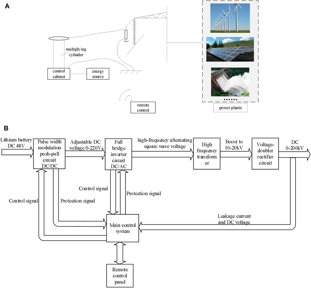
FIGURE 1. Composition of DC test system. (A) Overall system framework; (B) Design block diagram of DC test system.
It is extremely difficult to obtain AC 220 V energy source for line arresters on-site. Meanwhile, the volume and weight of conventional 1 kW generators fail to satisfy on-site usage requirements. Thus, lithium battery is employed as an energy source for this test system. Besides, the test system is subject to restrictions with a rated power of 400 W, a continuously adjustable output DC voltage of 0–200 kV, and a maximum output current of 2 mA to meet the DC reference voltage test of 110 and 220 kV sectioned line arresters. Note that energy source power demand is calculated as 450 W according to 90% output efficiency. Mature batteries are lead-acid batteries and lithium batteries, among which lithium batteries perform advantages of large capacity, small size, and small weight. Therefore, 48 V/20 Ah lithium batteries are selected. Meanwhile, the test time of a single arrester generally does not exceed 5 min. A selected lithium battery discharging at 0.5°C can ensure the continuous operation of equipment for 2 h and satisfies continuous test of 24 line arresters.
In addition, the design block diagram of the DC test system is shown in Figure 1B. First, 48 V DC voltage of lithium battery pack is transformed to about 220 V continuously adjustable DC voltage (Xue et al., 2020) through pulse width modulation (PWM) push-pull circuit (Shi et al., 2016) and full bridge rectifier circuit in the control cabinet. And then, full bridge inverter circuit inverts DC voltage into a high-frequency alternating square wave voltage of 50–80 kHz (Jing et al., 2018; Zhang et al., 2021). Lastly, the voltage after initial boost is transferred to DC voltage with an amplitude of 200 kV through a voltage doubler rectifier circuit.
System Design of Power Driver and Control Circuit
Design of Power Driver and Control Circuit
Generally, the voltage-doubler rectifier mode of DC high-voltage generator adopts AC power supply, such as AC 220 or AC 380 V, and bus voltage is often rectified to DC 300 or DC 600 V. In this work, a lithium battery with 48 V DC voltage is adopted as the energy source to reduce its weight. If the voltage cannot be boosted to the rated voltage under the rated current via the original mode, the power driver and control circuit shall be redesigned. Considering the power limitation of lithium batteries, internal devices and software design with low power consumption shall be selected. Besides, the internal auxiliary energy source should not only achieve fast boosting speed but also ensure the stability and reliability of output voltage.
The power driver and control circuit of this test system consists of a pulse width modulation push-pull circuit and a full bridge rectifier circuit. Particularly, two power transistors or electronic tubes with the same parameters are adopted in the push-pull circuit to implement amplification in positive and negative half cycle waveforms, respectively. Meanwhile, only one of the two symmetrical power switches is turned on during working time, which effectively contributes to small conduction loss and high transformation efficiency. In addition, the pulse width modulator generates PWM waves to control the on-off state of transistors and adjust voltage and power by regulating the duty cycle of PWM waves.
The pulse width modulation push-pull circuit designed of the test system is shown in Figure 2A, where the output voltage of the transformer can be output in a push-pull manner by alternately turning on B 1 and B 2. Furthermore, the later stage is rectified by the full bridge to obtain a relatively smooth DC voltage, which is supplied to the full-bridge inverter. Otherwise, the driving part of the push-pull circuit adopts a chip SG1525, which has a double-ended output pulse width modulator that includes two independent output circuits with opposite phases. Besides, the main control chip of the control circuit adopts MSP430 series 16-bit mixed-signal processor with ultra-low power.
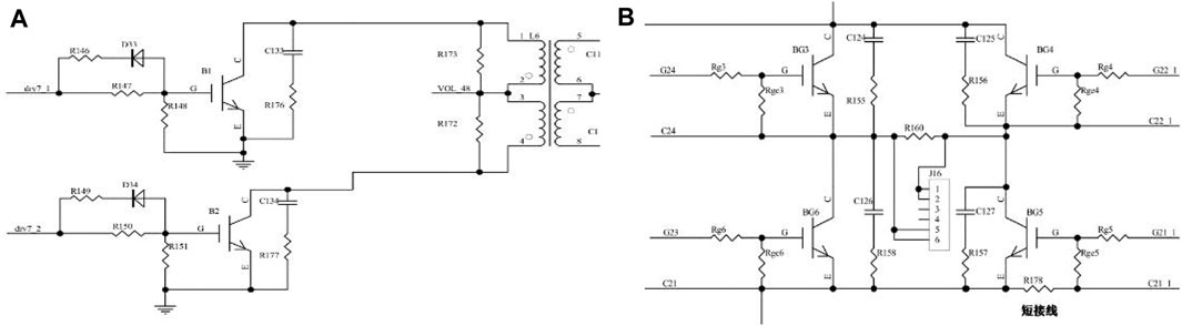
FIGURE 2. Circuit structure diagram. (A) Pulse width modulation push-pull circuit; (B) Full bridge inverter circuit.
The full-bridge inverter circuit is shown in Figure 2B, which is designed to reverse the DC voltage into a high-frequency AC square wave voltage. In particular, when BG 3 and BG 5 are turned on at the same time, BG 4 and BG 6 are turned off. On the contrary, if BG4 and BG 6 are turned on at the same time, BG 3 and BG 5 are turned off.
Design of Voltage-Doubler Rectifier Circuit
For the system design, a typical C-W voltage-doubler rectifier circuit is adopted. As illustrated in Figure 3A, the high-frequency AC square wave signal can reach up to 18 kV after passing through the high-frequency transformer, while the maximum output voltage amplitude is 200 kV and the magnification should not be less than 11.11 times. Practically, the output voltage will be reduced after loading. Therefore, the number of voltage doubler stages is finally determined to be seven levels. Besides, multiplying cylinder realizes a compact design via decreasing its size and optimizing the layout of main components, exhibited in Figure 3B.
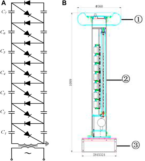
FIGURE 3. Voltage-doubler rectifier circuit. (A) Schematic diagram; (B) Design drawing.
Design of Remote Control Module
Because the majority of towers with line arresters are located in mountainous areas and the test areas under towers are seriously narrow, the remote control method is adopted to control the start, stop, and lifting of DC high-voltage generator to ensure the safety of test personnel (Tavakoli and Nafar, 2020). In addition, an infrared measuring circuit is arranged on the top of the multiplying cylinder while the main control chip MSP430 is used to measure the voltage and current signals at the high-voltage end. Furthermore, collected voltage and current signals are converted into infrared signals through protocol coding for transmission. An infrared receiving circuit in the control box is adopted to process the high-voltage end signal. Then, the control box exchanges the high-voltage end signal and other control signals with Bluetooth control box through Bluetooth communication. Note that the main control chip of Bluetooth remote control box adopts STM32f030 with ARM Cortex-M0 core to amplify signal through the front-end RF amplifier. Moreover, the reception and emission of wireless signals can be achieved by the way of controlling the remote equipment via a chip nRF24L01.
The main interface of the remote control module is employed to display the output voltage, current, current flowing through MOA of DC high-voltage generator, and the voltage of the lithium battery pack and test results in real time. Note that the on-off control of equipment as well as manual and automatic voltage rise and fall operations can also be achieved on the main interface.
Portable DC Test System and Test
The entire DC test system adopts a split design to facilitate transportation, which is divided into five parts i.e., multiplying cylinder, grade ring, control cabinet, energy source, and pressurized wire. Note that multiplying cylinder, grade ring, and control cabinet need to be assembled on site. It is worth noting that the assembled equipment is shown in Figure 4.
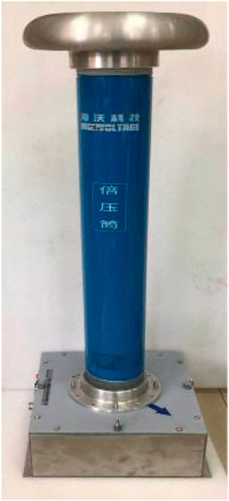
FIGURE 4. Compressed loop after assembly.
Furthermore, the total weight of this device is strongly reduced by optimizing voltage-doubler rectifier circuit and energy source, which is also convenient for transportation. Table 1 depicts the comparison of the weight of each component with traditional high-voltage DC generator. It is easy to see the weight of control cabinet, multiplying cylinder, and energy source part is reduced by 60, 54.55, and 33.33%, respectively, compared with traditional devices with the same parameters. The overall weight of the device is decreased by 36.7% even adding the remote control module.
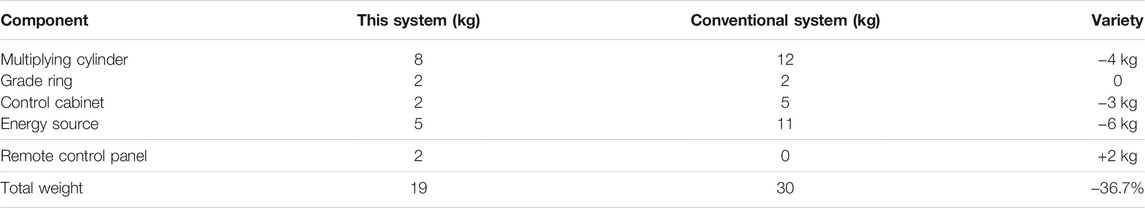
TABLE 1. Comparison of the weight of high-voltage DC generator.
In addition, the high-voltage voltage and current calibration data are measured in a laboratory to verify the test performance of the device. Consequently, the calibration results are revealed in Table 2 and Table 3, where the high-voltage voltage test accuracy and the high-voltage current test accuracy are less than 0.5 and 1%, respectively. From Table 4, it can be seen that under 5 tests, all the indices can be maintained at a relatively stable value, which further verifies its stability and accuracy during voltage tests.
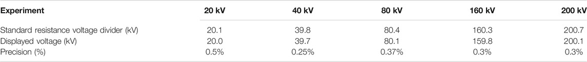
TABLE 2. High-voltage voltage calibration data.
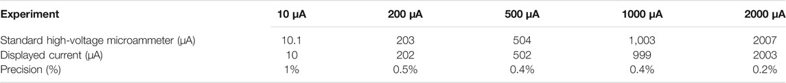
TABLE 3. High-voltage current calibration data.
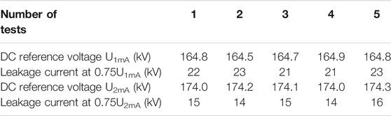
TABLE 4. Test results of the arrester.
The DC reference voltage test of the arrester (i.e., YH10W-108/281 arrester) is carried out in the laboratory, while the test wiring diagram is shown in Figure 5. Moreover, the arrester is tested with DC reference voltage under 1 and 2 mA, respectively, whose test results are presented in Table 4.
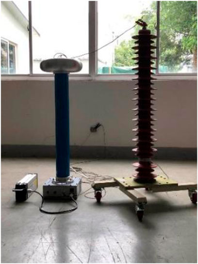
FIGURE 5. Laboratory wiring diagram.
Conclusion
In this article, a DC test system for transmission line arrester is developed, which owns the following novelty/contributions compared with conventional DC high-voltage generator:
1) The portability of the device is considerably improved. Compared with traditional devices with the same parameters, the total weight of this device is decreased by 36.7%. In particular, the weights of control cabinet, multiplying cylinder, and energy source are reduced by 60, 54.55, and 33.33%, respectively;
2) This device is more suitable for on-site tests. The system is powered by lithium battery instead of 220/380 V AC energy source, and adopts multiplying cylinder and control cabinet that can be transported separately, which realize integrated assembly on-site and facilitate line arrester test in the testing field;
3) The proposed device owns high safety during tests.The system accomplishes wireless transmission and control of the equipment through the control of infrared measurement circuit and Bluetooth remote control module, which ensures the personal safety of testers during the tests under the tower.
In future studies, great focus will still be put on the optimization of overall weight and portability of the device via more advanced design. Also, with the proper application of 5G technology, the speed of wireless transmission could be considerably improved to help engineers more quickly collect and convey device information.
Data Availability Statement
The original contributions presented in the study are included in the article/Supplementary Material, further inquiries can be directed to the corresponding author.
Author Contributions
YF: Conceptualization, Writing- Reviewing and Editing. KL: Writing- Original draft preparation, Investigation. MG: Writing- Reviewing and Editing. YL: Supervision. XL: Supervision. JZ: Conceptualization, Resources.
Conflict of Interest
YF, KL, and MG are employed by Yunnan Power Grid Co. Ltd. YL is employed by Guangdong Power Grid Co. Ltd. XL is employed by Suzhou Industrial Park Haiwo Science and Technology Co. Ltd.
The remaining author declares that the research was conducted in the absence of any commercial or financial relationships that could be construed as a potential conflict of interest.
Publisher’s Note
All claims expressed in this article are solely those of the authors and do not necessarily represent those of their affiliated organizations, or those of the publisher, the editors and the reviewers. Any product that may be evaluated in this article, or claim that may be made by its manufacturer, is not guaranteed or endorsed by the publisher.
References
Aberoumand, S., Ghamari, S., and Shabani, B. (2018). Energy and Exergy Analysis of a Photovoltaic thermal (PV/T) System Using Nanofluids: An Experimental Study. Solar Energy 165, 167–177. doi:10.1016/j.solener.2018.03.028
Alberto, D. C., Fernando, H., and Silveira, S. V. (2014). On the Role of Transformer Grounding and Surge Arresters on Protecting Loads from Lightning-Induced Voltages in Complex Distribution Networks. Electric Power Syst. Res. 113, 204–212. doi:10.1016/j.epsr.2014.02.035
Božidar, F., Ivo, U., and Ivica, P. (2016). Application of Line Surge Arresters for Voltage Uprating and Compacting of Overhead Transmission Lines. Electric Power Syst. Res. 140, 830–835. doi:10.1016/j.epsr.2016.04.023
Christodoulou, C. A., Ekonomou, L., Mitropoulou, A. D., Vita, V., and Stathopulos, I. A. (2010). Surge Arresters' Circuit Models Review and Their Application to a Hellenic 150kV Transmission Line. Simulation Model. Pract. Theor. 18 (6), 836–849. doi:10.1016/j.simpat.2010.01.019
Guchhait, P. K., and Banerjee, A. (2020). Stability Enhancement of Wind Energy Integrated Hybrid System with the Help of Static Synchronous Compensator and Symbiosis Organisms Search Algorithm. Prot. Control. Mod. Power Syst. 5 (2), 43–55. doi:10.1186/s41601-020-00158-8
Hemapala, K. T. M. U., Gnana Swathika, O. V., and Dharmadasa, K. P. R. D. S. K. (2018). Techno-economic Feasibility of Lighting protection of Overhead Transmission Line with Multi-Chamber Insulator Arrestors. Develop. Eng. 3, 100–116. doi:10.1016/j.deveng.2018.05.003
Hoang, T. T., Cho, M. Y., Alam, M. N., and Vu, Q. T. (2017). A Novel Differential Particle Swarm Optimization for Parameter Selection of Support Vector Machines for Monitoring Metal-Oxide Surge Arrester Conditions. Swarm Evol. Comput. 38, 120–126. doi:10.1016/j.swevo.2017.07.006
Hori, K., Kim, J., Kawase, R., Kimura, M., Matsui, T., and Machimura, T. (2020). Local Energy System Design Support Using a Renewable Energy Mix Multi-Objective Optimization Model and a Co-Creative Optimization Process. Renew. Energ. 156, 1278–1291. doi:10.1016/j.renene.2019.11.089
Jing, L., Yong, L., Wang, W. Y., Cao, Y. J., Lee, K. Y., and Fang, L. (2018). Fault-Ride through Control Strategy of Multi-Terminal High Voltage DC Systems. IFAC-PapersOnLine 51 (28), 540–545. doi:10.1016/j.ifacol.2018.11.759
Lei, Y., Wang, D., Jia, H., Chen, J., Li, J., Song, Y., et al. (2020). Multi-Objective Stochastic Expansion Planning Based on Multi-Dimensional Correlation Scenario Generation Method for Regional Integrated Energy System Integrated Renewable Energy. Appl. Energ. 276, 115395. doi:10.1016/j.apenergy.2020.115395
Liu, Z., Gao, H., Luo, S., Luo, S. B., Zhao, L., and Feng, Y. Y. (2020). A Fast Boundary protection for an AC Transmission Line Connected to an LCC-HVDC Inverter Station. Prot. Control. Mod. Power Syst. 5 (4), 25–38. doi:10.1186/s41601-020-00175-7
Malcolm, N., and Aggarwal, R. K. (2015). The Impact of Multiple Lightning Strokes on the Energy Absorbed by MOV Surge Arresters in Wind Farms during Direct Lightning Strikes. Renew. Energ. 83, 1305–1314. doi:10.1016/j.renene.2015.05.010
Marcel, A., Rogério, A., Ruy, A. C., Oureste, E. B., and Lucas, A. M. (2015). Practical Methodology for Modeling and Simulation of a Lightning protection System Using Metal-Oxide Surge Arresters for Distribution Lines. Electric Power Syst. Res. 118, 47–54. doi:10.1016/j.epsr.2014.07.017
Muniappan, M. (2021). A Comprehensive Review of DC Fault protection Methods in HVDC Transmission Systems. Prot. Control. Mod. Power Syst. 6, 1–20. doi:10.1186/s41601-020-00173-9
Petar, S., Josip, V., and Ranko, G. (2013). Monte Carlo Analysis of Wind Farm Surge Arresters Risk of Failure Due to Lightning Surges. Renew. Energ. 57, 626–634. doi:10.1016/j.renene.2013.03.004
Sandrode, C. A., Wallacedo, C. B., José, S. P., and Rubens, L. M. (2017). Lightning Performance of Transmission Line with and without Surge Arresters: Comparison between a Monte Carlo Method and Field Experience. Electric Power Syst. Res. 149, 169–177. doi:10.1016/j.epsr.2017.04.012
Seyyedbarzegar, S. M., and Mirzaie, M. (2015). Application of Finite Element Method for Electro-Thermal Modeling of Metal Oxide Surge Arrester. Comput. Appl. Eng. Educ. 23 (6), 910–920. doi:10.1002/cae.21663
Shi, L.-F., Shi, Z.-B., Chen, S., and Xun, J.-H. (2016). Output Voltage Sampling Circuit for Discontinuous Conduction Mode Flyback Pulse-Width Modulation Controller. J. Circuit Syst. Comp. 25 (11), 1650140. doi:10.1142/s0218126616501401
Silverio, V., Fernando, H., Silveira, B. P., and Rafael, M. (2020). Constraints on the Use of Surge Arresters for Improving the Back Flashover Rate of Transmission Lines. Electric Power Syst. Res. 180, 106064. doi:10.1016/j.epsr.2019.106064
Tahir, M. F., Haoyong, C., and Guangze, H. (2021). A Comprehensive Review of 4E Analysis of thermal Power Plants, Intermittent Renewable Energy and Integrated Energy Systems. Energ. Rep. 7, 3517–3534. doi:10.1016/j.egyr.2021.06.006
Tavakoli, M., and Nafar, M. (2020). Human Reliability Analysis in Maintenance Team of Power Transmission System protection. Prot. Control. Mod. Power Syst. 5 (1), 1–13. doi:10.1186/s41601-020-00176-6
Vita, V., and Christodoulou, C. A. (2016). Comparison of ANN and Finite Element Analysis Simulation Software for the Calculation of the Electric Field Around Metal Oxide Surge Arresters. Electric Power Syst. Res. 133, 87–92. doi:10.1016/j.epsr.2015.11.041
Xue, A., Yue, L., Zhang, J., Cui, J., Li, Z., Li, Y., et al. (2020). A New Quantitative Analysis Method for Overvoltage in Sending End Electric Power System with UHVDC. IEEE Access 8, 145898–145908. doi:10.1109/access.2020.3015267
Zhang, B., Hu, W., Li, J., Cao, D., Huang, R., Huang, Q., et al. (2020). Dynamic Energy Conversion and Management Strategy for an Integrated Electricity and Natural Gas System with Renewable Energy: Deep Reinforcement Learning Approach. Energ. Convers. Manage. 220, 113063. doi:10.1016/j.enconman.2020.113063
Zhang, Y., Wang, S., Liu, T., Zhang, S., and Lu, Q. (2021). A Traveling-Wave-Based protection Scheme for the Bipolar Voltage Source Converter Based High Voltage Direct Current (VSC-HVDC) Transmission Lines in Renewable Energy Integration. Energy 216, 119312. doi:10.1016/j.energy.2020.119312
Keywords: line arrester, DC reference voltage test, portable, field test, transmission line
Citation: Feng Y, Li K, Gao M, Liu Y, Li X and Zhu J (2021) Optimal Operation and Control Design of DC Arrester for Renewable Energy Transmission. Front. Energy Res. 9:759434. doi: 10.3389/fenrg.2021.759434
Received: 16 August 2021; Accepted: 13 September 2021;
Published: 28 October 2021.
Edited by:
Xiaoshun Zhang, Shantou University, ChinaReviewed by:
Yixuan Chen, The University of Hong Kong, Hong Kong, SAR ChinaLiang Chao, The State Key Laboratory of Scientific and Engineering Computing (LSEC), China
Xuehan Zhang, Korea University, South Korea
Copyright © 2021 Feng, Li, Gao, Liu, Li and Zhu. This is an open-access article distributed under the terms of the Creative Commons Attribution License (CC BY). The use, distribution or reproduction in other forums is permitted, provided the original author(s) and the copyright owner(s) are credited and that the original publication in this journal is cited, in accordance with accepted academic practice. No use, distribution or reproduction is permitted which does not comply with these terms.
*Correspondence: Jiawei Zhu, amlhd2VpLnpodUBjaGQuZWR1LmNu