 Jie Jia
 Xuan Zhou1
 Yuanda Cheng
- 1Department of Built Environment and Energy Utilization Engineering, Taiyuan University of Technology, Taiyuan, China
- 2Taiyuan Lvjia Environmental Protection Development Co., Taiyuan, China
- 3Department of Building Services Engineering, The Hong Kong Polytechnic University, Kowloon, Hong Kong SAR, China
The simultaneous need for energy efficiency and indoor comfort may not be met by existing air source heat pump (ASHP) technology. The novelty of this study lies in the use of a new gravity-driven radiator as the indoor heating terminal of ASHPs, aiming to provide an acceptable indoor comfort with improved energy efficiency. To confirm and quantify the performance improvement due to the proposed system retrofit, a field test was conducted to examine the system performance under real conditions. In the tests, measurements were made on the refrigerant- and air-side of the system to characterize its operational characteristics. Results showed that the proposed radiator has a rapid thermal response, which ensures a fast heat output from the system. The proposed system can create a stable and uniform indoor environment with a measured air diffusion performance index of 80%. The energy efficiency of the proposed system was also assessed based on the test data. It was found that the system’s first law efficiency is 42.5% higher than the hydraulic-based ASHP system. In terms of the second law efficiency, the compressor contributes the most to the overall system exergy loss. The exergy efficiency of the proposed system increases with the outdoor temperature and varies between 35.02 and 38.93% in the test period. The research results and the analysis methodology reported in this study will be useful for promoting the technology in search of energy efficiency improvement in residential and commercial buildings.
Introduction
Air source heat pump (ASHP) is widely recognized as an energy efficient and cost effective means to provide space heating in buildings (Dai et al., 2020; Yang et al., 2020). It functions to transfer heat from outdoors to an indoor space with the aid of electrical work. As an ASHP operates based on vapor compression cycle, its heat output is constantly higher than the electricity input to provide an energy efficiency ratio always greater than unity (Chen et al., 2021; Zendehboudi et al., 2021).
Traditional ASHP system uses indoor air as heat carrier medium (referred to as the air-based system). In this system, indoor air is re-circulated and heated by the heat pump to compensate the space heat losses in winter (Zhang et al., 2017). This approach is featured by a rapid room temperature response, but it also has some limitations. First, the heated supply air with higher temperature will flow upward in the room due to buoyancy effect, thus leading to lower local air temperature in occupation zone. In practice, the resulting vertical temperature difference can be as high as 6–8°C (Zhang, 2015). Comfort temperature in occupation zone may be achieved by increasing the heat output from the ASHP, but this will inevitably increase the space heating energy consumption. Second, the thermal radiation effect introduced by the air-based system is negligible, which may result in low mean radiant temperature (MRT) of the space and adversely affects the human comfort (Walikewitz et al., 2015; Guo et al., 2020).
In view of the above limitations, hydraulic-based emitters are proposed in previous studies to be used as the indoor heating terminal of ASHPs (referred to as the hydraulic-based system) (Hewitt et al., 2011; Kelly and Cockroft, 2011). In this case, hydraulic-based emitters (e.g., radiators and radiant floor) are employed and installed in the room as heat dissipation device, and the ASHP is used only as a heat source. Since the hydraulic-based emitters dissipate heat by both convection and radiation, it can effectively reduce the radiative heat losses from human body in winter. Meanwhile, when compared with the air-based system, the use of hydraulic-based emitters can provide a relatively uniform indoor temperature, which further enhances the comfort level of the indoor environment (Myhren and Holmberg, 2008; Lin et al., 2016).
However, the use of the hydraulic-based emitters will incur additional pump energy use. Zhang measured the operating efficiency of a hydraulic-based system in a typical residence in the rural area of Beijing, China (Zhang, 2015). Results showed that the pump energy use accounts for 25–34% of the overall system consumption during winter, which is equivalent to a loss of about 30% of the heat pump efficiency.
This study contributes to the literature by proposing a novel gravity-driven radiator for use as the indoor heating terminal of ASHPs. The radiator uses gravity as the driving force for water circulation, thus eliminating the pump energy use in the hydraulic-based ASHP system. A field test was performed to examine the operational characteristics and performance of the proposed system. Based on the test results, the first and second law efficiency of the system are evaluated and discussed.
Proposed System
The gravity-driven radiator proposed in this study was retrofitted from a steel plate-type radiator. Its schematic is shown in Figure 1. To enable heat exchange between the radiator and the ASHP, a tube-in-tube heat exchanger was installed on the external of the original radiator. The inner tube of the heat exchanger is the refrigerant flow path, and the outer tube is the water flow path. When being heated by compressor discharge refrigerant, water flows upward in the heat exchanger due to buoyancy effect. In the radiator, the water dissipates heat to the indoor space by convection and radiation, leading to a temperature decrease and thus a downward flow due to gravity difference. Subsequently, the water returns to the heat exchanger, where it is being heated again. It can be seen that the radiator uses gravity as the driving force for water circulation, implying that no additional pump work is needed and the associated energy consumption is eliminated. Unlike common radiators used in district heating, water is encapsulated in the proposed radiator, thus the possibility of fouling is minimized. The schematic of the ASHP system using the proposed radiator as indoor heating terminal is shown in Figure 2.
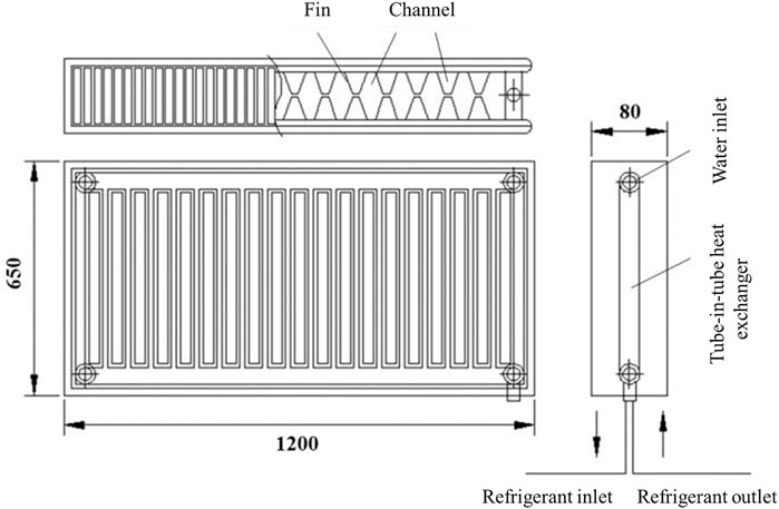
FIGURE 1. Schematic of the proposed gravity-driven radiator (unit: mm) T: Thermocouple; P: Pressure sensor; V: Flow meter.

FIGURE 2. Schematic of the proposed ASHP system.
Methodology
Field Test
In order to examine the operational characteristics and performance of the proposed ASHP system, a field test was conducted. The test was performed in a 74 m2 office located in Taiyuan, China. Five double-glazed windows were installed on the external walls of the office, as shown in Figure 3. Gravity-driven radiators were installed and placed under each external window. The radiators were connected in a parallel arrangement.
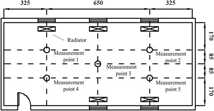
FIGURE 3. Arrangement of radiators and measuring points (unit: mm).
The ASHP used in the field test had a rated heating capacity of 4 kW and input power of 1.7 kW. The heat pump had a dual rotor compressor with a maximum allowable discharge and suction pressure of 4.2 and 1.5 MPa, respectively. An electronic expansion valve was used as the expansion device. Frost removal on the evaporator coil was realized by the common reverse-cycle defrosting method.
The measuring points on the refrigerant-side were located at the inlet and outlet of each system component as shown in Figure 2. Air temperature and humidity entering and leaving the heat pump’s evaporator were measured in real time using a hygrometer sensor. Thermocouples were used to measure the temperature distribution in the test room. Air temperatures were measured at five positions (1–5 in Figure 3) and three levels (0.1, 1.1, and 1.7 m height above the floor.). The above heights correspond to the height of the occupants’ ankle as well as the height of the occupants’ head when sitting and standing, respectively. Therefore, there were altogether 15 measuring points in the test room. Besides, the power consumption of the heat pump was measured using a power meter. The measurement instruments, which are summarized in Table 1, were connected to a data logger for real-time transmission and recording of test data.
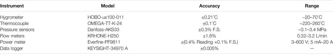
TABLE 1. Specific parameters of each measuring instrument.
The test period was from 22nd February to 28th February. The test could be divided into two stages. The first stage focused on the thermal response of the radiator during the system start-up. The second stage measured the quasi-steady performance of the system, where the test data sampling interval was set as 30 s. To confirm the validity of the test data obtained, the heat transfer of the system’s evaporator was calculated from both the refrigerant-side and air-side. It was found that the deviation between the two sets of data was less than 5%, thus confirming the reliability of the test data.
First Law Analysis
Based on the test data, the instantaneous heat output (q in kW) of the system can be calculated by:
where t is time, s; mr is the mass flow rate of the refrigerant, kg/s; Δh is the specific enthalpy difference of the refrigerant across the tube-in-tube heat exchanger (see Figure 2), kJ/kg.
The cumulative heat output (Q in kWh) in a certain time period (Δτ) can be calculated by:
Similarly, the cumulative power consumption (W in kWh) of the system in the time period Δτ can be given by:
where w is the instantaneous power consumption of the heat pump’s compressor, kW.
In this study, the first law efficiency of the system is characterized by a Coefficient of Performance (COP), which is defined as the amount of heat output per unit of electrical power consumed:
Second Law Analysis
The second law efficiency of the proposed system is evaluated by assessing the exergy at the inlet and outlet of each system component (Castelli et al., 2019). In this light, the equations for exergy analysis are established, which can be solved explicitly in sequence with measured refrigerant temperatures and pressures as model inputs.
The system satisfies (Zhang et al., 2019):
where Ein is the exergy input to the system, W; Eout is the exergy output from the system, W; ΔE is the exergy loss, W.
The exergy of refrigerant flow can be calculated using:
where h is the specific enthalpy of refrigerant, kJ/kg; T0 is the ambient temperature, K; h0 is the specific enthalpy of refrigerant at T0, kJ/kg; s is the specific entropy of refrigerant, kJ/kg K; s0 is the specific entropy of refrigerant at T0, kJ/kg K.
The exergy input to the radiator can be written as:
The exergy output from the radiator can be written as:
Therefore, the exergy loss of the radiator can be given as:
where φb is φ at point b (see Figure 2), kJ/kg; φc is φ at point c, kJ/kg; Ts is the surface temperature of the radiator, K; q is the heat dissipation of the radiator, kW.
Similarly, the exergy loss of the expansion valve can be calculated by:
where φd is φ at point d, kJ/kg.
The exergy loss of the evaporator can be calculated by:
where φa is φ at point a, kJ/kg.
The exergy loss of the compressor can be calculated by:
where w is the power consumption of the compressor, kW.
The overall system exergy loss is the sum of the losses from various components:
Therefore, the second law efficiency of the system can be expressed as:
Note that for an ideal (i.e., reversible) system, the second law efficiency ηsys equals to unity. The contribution of various components (e.g., radiator) to overall system loss can be evaluated by a fractional loss, which is defined as the ratio of the component exergy loss to the overall system loss.
Results and Discussion
Thermal Response of the Proposed Radiator
In this section, the thermal response of the proposed gravity-driven radiator was examined during the system start-up. An Infrared Thermal Imager was used to record the radiator surface temperature by taking pictures at 15 min intervals after the heat pump was switched on. Results are shown in Figure 4. The radiator was in temperature equilibrium at time zero. Upon switching on the heat pump, the radiator surface temperature increased rapidly and became stable at 43.1°C after about 90 min, resulting in an average rate of temperature rise of 25.5°C/h (for the whole radiator surface). However, for a typical radiant floor heating system, this rate can be as low as 1.2°C/h. This is because the radiant floor and the circulating water itself have large thermal mass. In practice, this thermal mass can create a considerable lag for heat output from an ASHP and potentially leads to occupants’ complaint. Consequently, the use of the proposed radiator can ensure a fast heat output from the system.
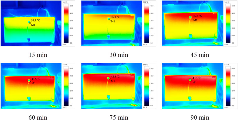
FIGURE 4. Radiator temperature during the system start-up.
In addition, as seen in Figure 4, the radiator has a higher surface temperature in the upper part, and the maximum vertical temperature difference is about 4°C. This is due to the heat transfer between the circulating water and the indoor environment, which causes a decrease in water temperature along the flow direction. The resulting density difference is the driving force for water circulation in the proposed radiator.
Indoor Thermal Environment
During the test period, the outdoor temperature fluctuated within the range of −2.4–10.6°C, while the measured average indoor temperature was maintained at the set-point of 20°C, indicating that the proposed system is able to create a relatively stable and comfort indoor temperature. To further explore the temperature distribution in the test room, the measured data on 22nd February were selected for a detailed study. The average temperatures at 0.1, 1.1, and 1.7 m height above the floor are shown in Figure 5. As can be seen, a vertical temperature difference exists in the room. This is due to the buoyancy effect of heated air, leading to a higher temperature in the upper part of the room. The maximum temperature difference between 0.1 and 1.1 m as well as that between 0.1 and 1.7 m is found to be 2.2 and 3.3°C, respectively, which satisfies the requirements specified by ASHRAE Standard 55 (ANSI/ASHRAE, 2020) for acceptable thermal environment. Therefore, as compared with the air-based system, the use of the proposed radiators can mitigate the adverse effects due to uneven temperature distribution and enhance the comfort level of an indoor environment served by ASHP.
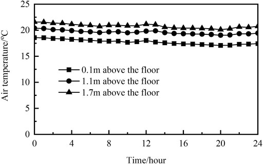
FIGURE 5. Indoor temperature distribution.
Air diffusion performance index (ADPI), as defined by ASHRAE Standard 113 (ANSI/ASHRAE, 2009), was used to quantity the air diffusion performance and thus thermal comfort for the test room because it considers two main thermal comfort variables (i.e., air temperature and velocity). ADPI is taken as the percentage of the measuring points that can meet the human comfort requirements. A larger ADPI generally means a better air distribution performance (Liu and Novoselac, 2015). Under winter heating conditions, people are considered comfortable when the effective draft temperature (EDT) at a measuring point is maintained within the range of −1.7–1.1°C. In the context of this study, EDTs at various measuring points (see Figure 3) were calculated and the obtained results are shown in Table 2.
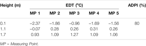
TABLE 2. EDT at different measuring points.
As seen in Table 2, ADPI reaches 80% for the proposed system. As a contrast, indoor environment served by traditional air-based ASHP system typically has an ADPI of only ∼30% (Wang, 2002). This demonstrates that the use of the proposed radiators can effectively reduce the vertical temperature difference in the room, where a majority of the measuring points have an EDT well within the acceptable range.
Operational Characteristics and First Law Efficiency
The compressor suction and discharge pressure changes during the system start-up are shown in Figure 6. It can be seen that upon the heat pump is switched on, the discharge pressure rises rapidly and becomes stable afterward. The time required to reach the steady state is about 90 min, which is consistent with the dynamic behavior of the radiator (see Figure 4). In addition, the discharge pressure changes more significantly than the suction pressure because of the sharp increase in radiator temperature during the system start-up. After reaching a steady state, the suction and discharge pressures are found to be 0.8 and 3.5 MPa, respectively, which are well within their respective operation limit to ensure a stable operation of the compressor.
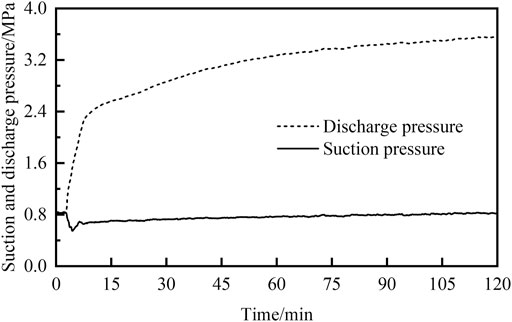
FIGURE 6. Suction and discharge pressures during the system start-up.
To assess the steady state performance of the proposed system, the obtained test data are hourly averaged. The compressor suction and discharge pressures on hourly basis during the test period are shown in Figures 7, 8, respectively. It can be seen that for stable operation, the compressor suction pressure is closely related to the outdoor temperature, while the discharge pressure is mainly dependent on the radiator temperature. The first law efficiency of the system varies with the above parameters. The hourly COP of the proposed system is given in Figure 9. As can be seen, the system COP is mainly affected by the outdoor temperature. During the test period, the hourly COP varies between 1.83 and 3.33. As the outdoor temperature increases, the evaporating pressure elevates to decreases the compression ratio as well as the specific volume of refrigerant at compressor suction. Therefore, the system operates under favorable operating conditions, thus yielding a higher COP value.
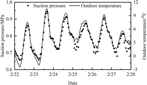
FIGURE 7. Hourly suction pressure during the test period.
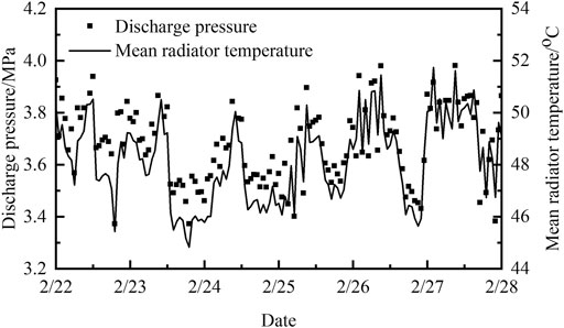
FIGURE 8. Hourly discharge pressure during the test period.
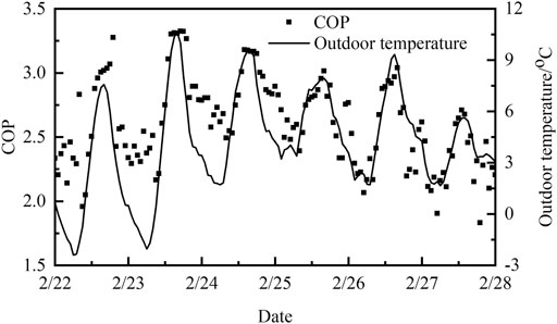
FIGURE 9. Hourly COP of the system during the test period.
To further understand the energy efficiency of the proposed system, the daily cumulative heat output, power consumption and average COP of the system during the test period were calculated. The daily COP of the system ranges between 2.22 and 2.78 with an average over the test period of 2.51. To enable a comparison of the COP between different ASHP systems, references were made to previous studies (Xiao et al., 2010; Zhou et al., 2013). Relevant information is shown in Table 3. It is revealed that under similar outdoor temperatures, the proposed system’s COP is comparable with the air-based system but 42.5% higher than the hydraulic-based system. This energy efficiency improvement is mainly due to the elimination of pump energy use in the hydraulic-based system. Therefore, the proposed system is capable of creating a comfort indoor environment without compromising the heat pump’s energy efficiency.

TABLE 3. Comparison of COP for different systems.
Second Law Efficiency
In this section, five sets of data at outdoor temperatures of −2, 0, 2, 4, and 6°C were selected to evaluate the exergy performance of the proposed system as discussed in Second law analysis. Results are shown in Table 4. Among various system components, the compressor has the largest exergy loss, which varies between 551.42 and 927.23 W. This is due to the fact that non-isentropic compression is involved, of which the irreversibility is considerable. Further, the compressor exergy loss decreases with an increase in outdoor temperature. This is because as the outdoor temperature increases, the evaporating temperature also increases to result in a decrease in compression ratio as well as the irreversible compressor work. The fractional loss of the compressor reaches the minimum value of 43.01% when the outdoor temperature is 6°C. But it still contributes the most in the overall system exergy loss.
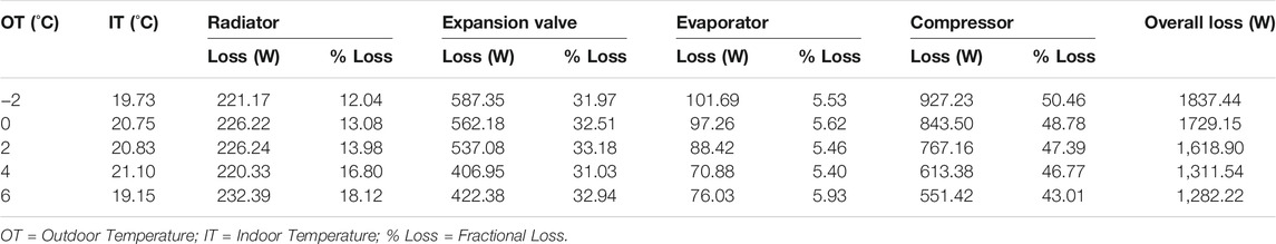
TABLE 4. Exergy losses from different system components.
The exergy loss due to expansion valve varies between 406.95 and 587.35 W. As the outdoor temperature elevates, the corresponding loss decreases. This is because as the outdoor temperature increases, the evaporating temperature increases to result in a decrease in the temperature difference of refrigerant across the expansion valve. For the studies outdoor temperature range, the fractional loss of expansion valve remains relatively stable and varies between 31.03 and 33.18%. The radiator exergy loss varies within the range of 220.33–232.39 W. The evaporator has the lowest exergy loss among the system components, only accounting for 5.40–5.93% of the overall system exergy loss.
Generally, an increase in the outdoor temperature can improve the system’s exergy performance. This is due to the fact that the compressor power decreases with increased outdoor temperature, and the irreversibility due to non-isentropic compression is the main source of exergy loss in the proposed system. For the studied outdoor temperature range, the proposed system has a relatively high exergy efficiency varying between 35.02 and 38.93%. To enable a comparison of the exergy performance between different heating systems, references were made to previous studies (Wen and Ma, 2003). Relevant information is shown in Table 5.
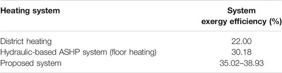
TABLE 5. Exergy efficiency comparison for different heating systems.
As can be seen from Table 5, the exergy efficiency of the proposed system is comparable with the hydraulic-based system using radiant floor as indoor heating terminal, but 15% higher than the district heating system. Therefore, the proposed system can be considered as a promising ASHP technology for further deployment in the building industry.
Conclusion
This study contributes to the literature by proposing a novel gravity-driven radiator for use as the indoor heating terminal of air source heat pump. The radiator uses gravity as the driving force for water circulation, thus eliminating the pump energy use in the hydraulic-based heat pump system. A field test was performed to examine the operational characteristics and performance of the proposed system. It was found that the proposed radiator has a rapid thermal response, which ensures a fast heat output from the system. The proposed system can create a stable and uniform indoor environment with a measured air diffusion performance index of 80%. The first and second law efficiency of the proposed system was also assessed based on the test data. It was found that the system’s first law efficiency is 42.5% higher than the hydraulic-based system, and is comparable with the traditional air-based system. In terms of second law efficiency, the compressor contributes the most to the overall system exergy loss. The exergy efficiency of the proposed system varies between 35.02 and 38.93% in the test period. The above findings confirmed that the proposed system can create a comfort indoor environment with relatively high energy efficiency, making it a promising solution for space heating in the building industry.
Data Availability Statement
The raw data supporting the conclusion of this article will be made available by the authors, without undue reservation.
Author Contributions
JJ, Conceptualization, Methodology, Formal analysis, Investigation, Software, Resources, Data Curation, Writing—Original Draft, Writing—Review and Editing, Funding acquisition, Visualization. XZ, Conceptualization, Writing—Original Draft, Writing—Review and Editing. WF, Conceptualization, Writing—Original Draft, Writing—Review and Editing. YC, Conceptualization, Writing—Original Draft, Writing—Review and Editing. QT, Conceptualization, Writing—Original Draft, Writing—Review and Editing. FL, Conceptualization, Writing—Original Draft, Writing—Review and Editing. YC, Conceptualization, Writing—Original Draft, Writing—Review and Editing. WL, Conceptualization, Writing—Original Draft, Writing—Review and; Editing.
Funding
The authors appreciated the financial supports from the National Natural Science Foundation of China (No. 51808372), and Key Research and Development (R and D) Projects of Shanxi Province (No. 201903D121037).
Conflict of Interest
YC is employed by Taiyuan Lvjia Environmental Protection Development Co.
The remaining authors declare that the research was conducted in the absence of any commercial or financial relationships that could be construed as a potential conflict of interest.
Publisher’s Note
All claims expressed in this article are solely those of the authors and do not necessarily represent those of their affiliated organizations, or those of the publisher, the editors, and the reviewers. Any product that may be evaluated in this article, or claim that may be made by its manufacturer, is not guaranteed or endorsed by the publisher.
References
ANSI/ASHRAE (2009). ASHRAE Standard 113: Method of Testing for Room Air Diffusion. Atlanta: American Society of Heating, Refrigerating and Air-Conditioning Engineers.
ANSI/ASHRAE (2020). ASHRAE Standard 55: Thermal Environmental Conditions for Human Occupancy. Atlanta: American Society of Heating, Refrigerating and Air-Conditioning Engineers.
Castelli, A. F., Elsido, C., Scaccabarozzi, R., Nord, L. O., and Martelli, E. (2019). Optimization of Organic Rankine Cycles for Waste Heat Recovery from Aluminum Production Plants. Front. Energ. Res. 7, 44. doi:10.3389/fenrg.2019.00044
Chen, S., Friedrich, D., and Yu, Z. (2021). Optimal Sizing of a Grid Independent Renewable Heating System for Building Decarbonisation. Front. Energ. Res. 9, 455. doi:10.3389/fenrg.2021.746268
Dai, B., Qi, H., Dou, W., Liu, S., Zhong, D., Yang, H., et al. (2020). Life Cycle Energy, Emissions and Cost Evaluation of CO2 Air Source Heat Pump System to Replace Traditional Heating Methods for Residential Heating in China: System Configurations. Energ. Convers. Manag. 218, 112954. doi:10.1016/j.enconman.2020.112954
Guo, H., Aviv, D., Loyola, M., Teitelbaum, E., Houchois, N., and Meggers, F. (2020). On the Understanding of the Mean Radiant Temperature within Both the Indoor and Outdoor Environment, a Critical Review. Renew. Sust. Energ. Rev. 117, 109207. doi:10.1016/j.rser.2019.06.014
Hewitt, N. J., Huang, M. J., Anderson, M., and Quinn, M. (2011). Advanced Air Source Heat Pumps for UK and European Domestic Buildings. Appl. Therm. Eng. 31, 3713–3719. doi:10.1016/j.applthermaleng.2011.02.005
Kelly, N. J., and Cockroft, J. (2011). Analysis of Retrofit Air Source Heat Pump Performance: Results from Detailed Simulations and Comparison to Field Trial Data. Energy and Buildings 43, 239–245. doi:10.1016/j.enbuild.2010.09.018
Lin, B., Wang, Z., Sun, H., Zhu, Y., and Ouyang, Q. (2016). Evaluation and Comparison of thermal comfort of Convective and Radiant Heating Terminals in Office Buildings. Building Environ. 106, 91–102. doi:10.1016/j.buildenv.2016.06.015
Liu, S., and Novoselac, A. (2015). Air Diffusion Performance index (ADPI) of Diffusers for Heating Mode. Building Environ. 87, 215–223. doi:10.1016/j.buildenv.2015.01.021
Myhren, J. A., and Holmberg, S. (2008). Flow Patterns and thermal comfort in a Room with Panel, Floor and wall Heating. Energy and buildings 40, 524–536. doi:10.1016/j.enbuild.2007.04.011
Walikewitz, N., Jänicke, B., Langner, M., Meier, F., and Endlicher, W. (2015). The Difference between the Mean Radiant Temperature and the Air Temperature within Indoor Environments: A Case Study during Summer Conditions. Building Environ. 84, 151–161. doi:10.1016/j.buildenv.2014.11.004
Wang, Y. (2002). Measurement and Analysis of thermal Environment of Heated and Heat Pump Air Conditioned Rooms. Heating. Ventilating & Air Conditioning 32, 18–19. (in Chinese).
Wen, Z., and Ma, J. (2003). Study on Different Heating Methods in Beijing. District Heat. 3, 14–30. (in Chinese).
Xiao, Y., Zhang, C., and Fu, X. (2010). Experimental Studies on the Operation of Air Source Heat Pump in Extreme winter Weather. Acta Energiae Solaris Sinica 31, 1580–1584. (in Chinese).
Yang, Y., Li, R., Zhu, Y., Sun, Z., and Zhang, Z. (2020). Experimental and Simulation Study of Air Source Heat Pump for Residential Applications in Northern China. Energy and Buildings 224, 110278. doi:10.1016/j.enbuild.2020.110278
Zendehboudi, A., Zhao, J., and Li, X. (2021). Data-driven Modeling of Residential Air Source Heat Pump System for Space Heating. J. Therm. Anal. Calorim. 145, 1–14. doi:10.1007/s10973-021-10750-1
Zhang, L. (2015). Research on the Applicability of Small Low Temperature Air Source Heat Pump Heating in Beijing Rural Area. Beijing: Tsinghua University. (in Chinese).
Zhang, Q., Zhang, L., Nie, J., and Li, Y. (2017). Techno-economic Analysis of Air Source Heat Pump Applied for Space Heating in Northern China. Appl. Energ. 207, 533–542. doi:10.1016/j.apenergy.2017.06.083
Zhang, X., Deng, S., Zhao, L., Su, W., and Xu, W. (2019). Performance Analysis on a Power and Ejector-Refrigeration System and the Involved Ejector. Front. Energ. Res. 7, 117. doi:10.3389/fenrg.2019.00117
Keywords: air source heat pump, energy performance, gravity-driven radiator, indoor comfort, space heating
Citation: Jia J, Zhou X, Feng W, Cheng Y, Tian Q, Li F, Chen Y and Lee W (2021) Field Test on Performance of an Air Source Heat Pump System Using Novel Gravity-Driven Radiators as Indoor Heating Terminal. Front. Energy Res. 9:765781. doi: 10.3389/fenrg.2021.765781
Received: 27 August 2021; Accepted: 19 October 2021;
Published: 19 November 2021.
Edited by:
Ning Mao, The University of Tokyo, JapanReviewed by:
Wandong Zheng, Tianjin University, ChinaLong Zhang, Beijing Institute of Technology, China
Copyright © 2021 Jia, Zhou, Feng, Cheng, Tian, Li, Chen and Lee. This is an open-access article distributed under the terms of the Creative Commons Attribution License (CC BY). The use, distribution or reproduction in other forums is permitted, provided the original author(s) and the copyright owner(s) are credited and that the original publication in this journal is cited, in accordance with accepted academic practice. No use, distribution or reproduction is permitted which does not comply with these terms.
*Correspondence: Yuanda Cheng, Y2hlbmd5dWFuZGFAdHl1dC5lZHUuY24=