 D. Liang
 C. Song1
 Z. Zhou
- 1School of Electrical and Power Engineering, China University of Mining and Technology, Xuzhou, China
- 2Shandong Jirong Thermal Technology Co., Ltd., Jinan, China
- 3China National Nuclear Power Operations Management Co., Ltd., Jiaxing, China
With the aim of improving the aerodynamic performance of axial turbomachinery, a new type of blade is designed using the equal–variable circulation method. Taking an axial flow fan as the research object, this article describes the development of a new type of turbomachinery by changing the design method and producing a blade with forward sweep. The aerodynamic performance of the fan is simulated and compared with the experimental data. The numerical results show that the equal circulation design method improves the aerodynamic performance of the blade roots, while the variable circulation design method enhances the aerodynamic performance of the blade tips. By adopting the equal–variable circulation design method, the total pressure of the experimental fan is increased by about 4%, while the efficiency remains unchanged. Forward-swept blades with an equal–variable circulation design also improve performance over the conventional blades by changing the center-of-gravity stacking line. At low flow rates, the efficiency of the experimental fan can be increased by 7.5%, and the working range of the flow is expanded. Under high flow rates, the restriction of the blade tip on the airflow is decreased and the fluidity is slightly reduced.
1 Introduction
In industrial production, low-pressure axial fans are widely used because of their uncomplicated structure, large flow rates, and stable operation. In turbomachinery research, improved efficiency and reduced noise are long-standing topics of research. The modification of turbomachinery is mainly divided into three directions: airfoil modification, blade shape modification, and tip clearance modification (Peng et al., 2013; Rehman et al., 2018; Sreekanth et al., 2021).
In terms of airfoil modification, Pascu et al. (2009) and Cho et al. (2009) proposed a scheme for optimizing the blade arbitrary vortex design based on the NACA-65 series airfoil, and combined different types of design and optimization algorithms in a CFD solver to increase the blade load and efficiency. Liu et al. (Hongpeng et al., 2020) used three methods to minimize the drag coefficient, namely, affixing a zigzag trailing-edge to the trailing edge of the airfoil, using a slotted airfoil, and a combination of the zigzag method and the slotted airfoil. Sogukpinar (2018) created a new airfoil by changing the thickness of the pressure side to obtain high lift coefficient and post-stall airfoils. In general, the modification of the airfoil optimizes the aerodynamic performance.
In terms of blade shape modification, Hassan Saeed et al. (2019) modified four rotor blades and found that the new blade design performs better than other modifications. Lazari and Cattanei (2014) optimized a non-statistical axial flow fan based on the three-parameter vortex law and the meridian runner size. By considering the aerodynamic volume and proposing its corresponding variation range, and constraining the aerodynamic design to ensure that non-statistical design parameters were used, a good aerodynamic blade was obtained. Dugao et al. (Zhou and Jiang, 1996) proposed a new type of axial fan optimization design method, and Sorensen et al. (Sor̸ensen and Sor̸ensen, 2000; Sor̸ensen et al., 2000) improved this approach by using numerical methods. The application of optimization technology improves the performance of impeller machinery in terms of flow, torque, efficiency, pressure, and surge margin by changing the blade’s center-of-gravity stacking line (Place and Cumpsty, 1998; Wadia et al., 1998; Gallimore et al., 2002) and the blade profile line (Burguburu et al., 2004; Chen et al., 2005; Idahosa et al., 2008). Ahn (Adjei et al., 2019) and Jang and Kim (2007) used response surface approximation to optimize the blade profile. The abovementioned studies show that the efficiency can be improved by reducing the separation zone and correcting the corner vortex.
Previous research has shown that studying the flow characteristics of forward-swept structures applied to low-speed axial fans is of certain engineering significance. However, there has been little research on the optimization of forward-swept blades for low-pressure axial fans. This article proposes a new design method of low-pressure axial flow fan, which can effectively improve the operating range and parameters of low-pressure axial flow fan for engineering practice. Moreover, studying the deep reasons for the efficiency improvement and the optimization of internal flow has practical significance for further optimization of the blade.
2 Design Principle
2.1 Design Principle of Equal–Variable Circulation
For low-pressure axial fans, the design methods can be divided into equal circulation design and variable circulation design according to the law of airflow parameters along the blade height direction. The inlet and outlet flow of the axial flow turbomachinery blades is usually designed according to the free vortex mode:
where
Here,
where
Taking the derivative along the radial direction, we obtain
According to the radial balance equation,
Substituting Eqs 6, 1 into Eq. 5 and integrating yields
The equal circulation design method ignores the secondary radial flow and simplifies the flow of the airflow around the blade to an unmixed flow around many sections. In the variable circulation design method, the distribution of airflow parameters along the blade height does not satisfy the assumption that
During the blade design process, if the root load factor satisfies the necessary conditions, the equal circulation design and the variable circulation design can be combined to further optimize the aerodynamic shape of the blade. A blade root with a larger load factor can be designed using the equal circulation design method, while a tip with a smaller load factor can be designed with the variable circulation design method. Therefore, the equal–variable circulation design method effectively increases the chord length of each section of the blade, optimizes the aerodynamic shape of the blade, and increases the working force of the blade.
2.2 Design Principle of Forward-Swept Blades
The calculation model is constructed after the aerodynamic design calculation according to the equal–variable circulation design method. As a forward-swept blade is used in the experiments, this blade type is described in detail here. The reference airfoil for the blade design is the LS airfoil. According to the reference (Yang, 2008), the forward sweep of the blade ranges from 40 to 70% of the span, and the forward-sweep angle ranges from 10° to 20°. Three sections with different blade heights are shown in Figure 1. The specific parameters of the fan blade are listed in Table 1.
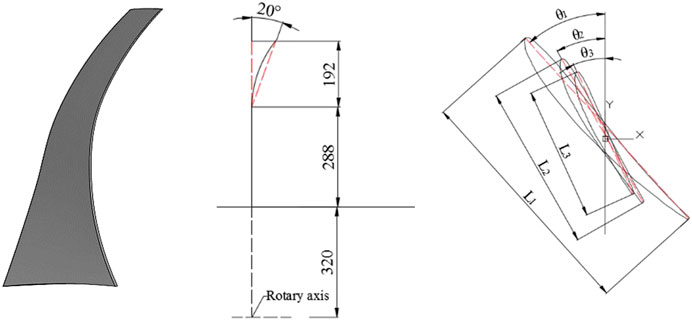
FIGURE 1. Center-of-gravity stacking line and airfoil: (A) forward-swept blade and (B) traditional blade.
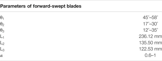
TABLE 1. Parameters of forward-swept blades.
3 Experimental and Numerical Methods
3.1 Experimental Methods
The experimental fan is a single-stage low-speed axial-flow fan, as is widely used for indoor ventilation in the textile industry. The experimental parameters are given in Table 2. The performance of axial flow fans can be tested with an experimental device. The device has a pressure sensor installed between the outlet of the collector and the inlet of the fan, and this sensor collects pressure signals and motor parameters, as shown in Figure 2. The hub ratio of the fan is 0.4, the rotation speed is 980–990 rpm, the outer diameter of the fan cylinder is 1,600 mm, the length of the intake cylinder is 4,000 mm, and the measured length is 4,815 mm.
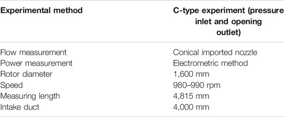
TABLE 2. Parameters of experimental device.
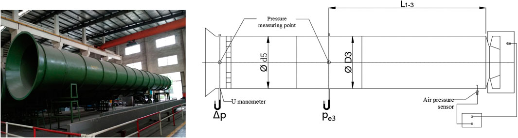
FIGURE 2. Experimental device.
3.2 Numerical Methods
In this study, ANSYS CFX was used for numerical simulations. The calculations use a single-flow-channel model. The physical model is divided into three regions: the inlet cylinder, fan rotor, and outlet cylinder. For the inlet and outlet, ICEM was used to divide the structural grid; for the rotor part, Autogrid was used to divide the grid to ensure sufficient grid quality. The single runner grid of the rotor is shown in Figure 3. The boundary conditions and convergence criteria are presented in Table 3.
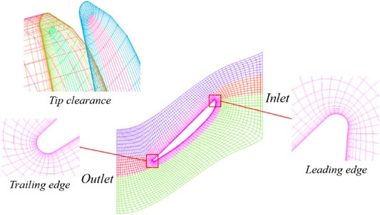
FIGURE 3. Grid of the blade runner.
TABLE 3. Boundary conditions and calculation convergence criteria.
To eliminate the influence of the grid resolution on the numerical results, four sets of rotor partial grids were selected for calculation. In the grid-independence verification, the SST
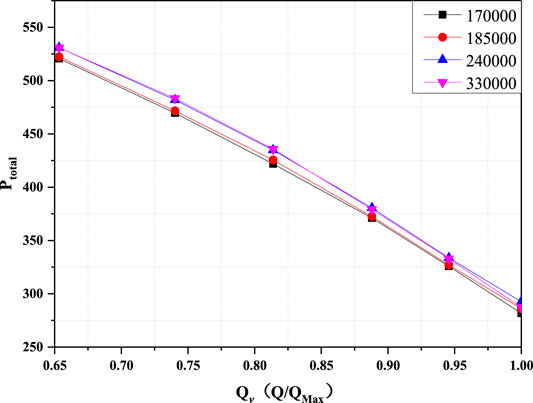
FIGURE 4. Verification of grid independence.
Different results can be obtained with different turbulence models, so the accuracy of the turbulence model was verified. As shown in Figure 5, the calculated total pressure given by the SST
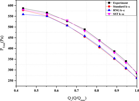
FIGURE 5. Comparison of numerical calculation and experimental results.
The calculation results of the SST
4 Results
4.1 Conventional Blade With Equal–Variable Circulation Design
Figure 6 compares the
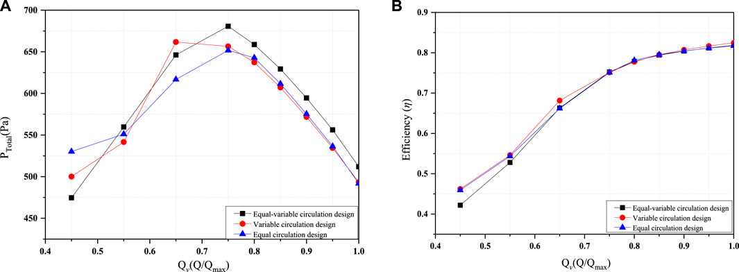
FIGURE 6. Traditional blade characteristic curves: (A)
It can be seen from Figure 6B that the efficiency of the equal–variable circulation design blade is basically the same as that of the other two blades. Thus, the equal–variable circulation design significantly increases the total pressure of the fan without affecting the efficiency.
Under rated flow conditions, the axial velocity of the fluid in the fan is an important parameter in determining the performance of the fan blade. Figure 7 shows the distribution of axial velocity (
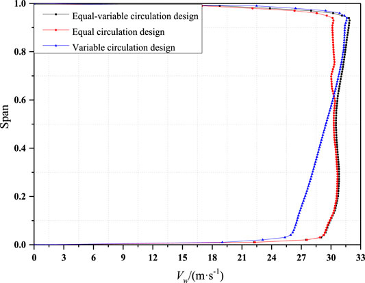
FIGURE 7. Axial velocity comparison at the exit.
Figure 8 shows the axial velocity and cross-sectional streamlines of the three blades at 20 and 80% of the span. By comparing the axial velocity of the three blades at 20% of the span, it can be seen that the equal–variable circulation design blade has significantly more high-speed areas on the suction surface than the variable circulation design blade. Combined with the conclusions obtained from Figure 7, it can be inferred that the equal–variable circulation design blade achieves better performance when the relative leaf height is small. The axial velocity distribution of the equal–variable circulation design blade is similar to that of the equal circulation design blade, which is also consistent with the conclusions indicated by Figure 7. The calculated average axial velocities of the equal–variable circulation design blade and the equal circulation design blade at 20% of the span are 30.2113 m/s and 29.8192 m/s, respectively, indicating that the equal–variable circulation design further optimizes the performance of the root of the blade. Comparing the axial speeds of the three blades at 80% of the span, the area of the high-speed region of the suction surface given by the equal–variable circulation design blade is significantly larger than that of the equal circulation design blade. The average speeds are 30.4782
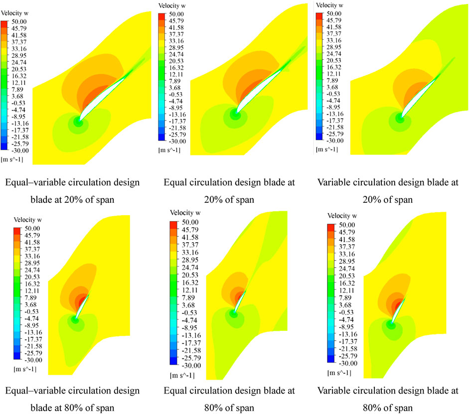
FIGURE 8. Axial velocity and cross-section streamlines of the three blades at 20 and 80% of the span.
4.2 Effect of Blade Forward Sweep
The blade’s center-of-gravity stacking line was modified on the basis of the equal–variable circulation design to obtain a forward-swept blade. In Figure 9, the forward-swept blade designed by the equal–variable circulation method has a wider stable working area than the traditional blade. This is because the forward-swept blade changes the blade tip profile, thus changing the inflow conditions, air flow structure, and blade load distribution in the blade tip area. These changes are conducive to the radial flow balance of the flow field and the transport of low-energy fluid at the blade tip. Under the full flow condition, the total outlet pressure and efficiency are the greatest when the initial blade height of the forward sweep is at 60% of the span. However, the blades show different characteristics under other flow conditions. The total pressure and efficiency are always maximized when the forward sweep starts at 60% of the span in forward-swept blades under full flow conditions, with an increase of up to 40 Pa and approximately 2%, respectively, compared with 50% of the span forward-swept blades. The 40 and 70% span forward-swept blades show similar aerodynamic performance, and their total pressure and efficiency are basically the same under all flow conditions. In conclusion, the starting height of the forward sweep has an effect on the aerodynamic performance of the blades. There is an optimum value that produces the best aerodynamic performance. For the fan studied in this article, the best aerodynamic performance can be obtained by starting the forward sweep at 60% of the span.
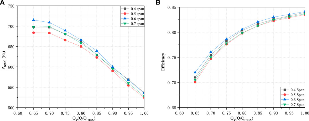
FIGURE 9. Performance curve of forward-swept blades at different starting heights.
Figure 10 compares the performance curves of forward-swept blades with different sweep angles. The results show that the forward-sweep angle has an effect on the aerodynamic performance of the blade and has an optimal value. The total pressure of blades with forward sweeps of 10° and 20° is higher than that of blades with a forward sweep of 15°. In addition, blades with 20° forward sweep are slightly higher than those with 10° forward sweep at low flow conditions, creating a differential of 15 Pa. The efficiency of blades with 20° forward-sweep angle is greater than that of other blades, with an improvement of 1.5% in maximum efficiency under the full flow condition.
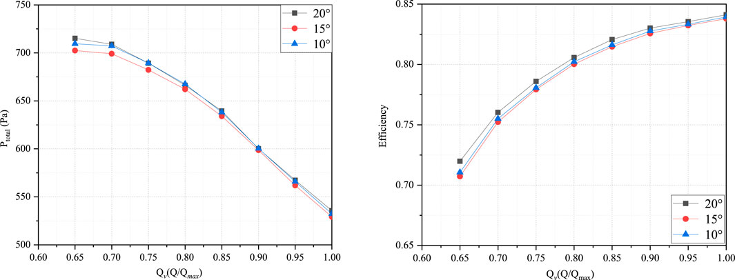
FIGURE 10. Performance curves of forward-swept blades with different forward-sweep angles.
4.3 Aerodynamic Performance Analysis of Forward-Swept Blades With Equal–Variable Circulation Design
Figure 11 compares the aerodynamic performance of a forward-swept blade and a conventional blade. It can be seen from Figure 11A that the conventional blade has a higher total pressure at high flow rates, indicating better aerodynamic performance. However, the forward-swept blade has a higher total pressure at low flow rates, suggesting a wider range of high pressures. Figure 11B shows that the forward-swept blade slightly improves the efficiency of the impeller under large-scale flows, and its efficiency is generally higher than that of the conventional blade. This is broadly similar to the conclusions obtained in the references. (Lazari and Cattanei, 2014; Zhou and Jiang, 1996; Sor̸ensen and Sor̸ensen, 2000; Sor̸ensen et al., 2000). In general, the performance of the conventional blade has been greatly improved by using a forward-swept blade. In the low flow condition, the forward-swept blade improves the efficiency of the fan by 7.5%.
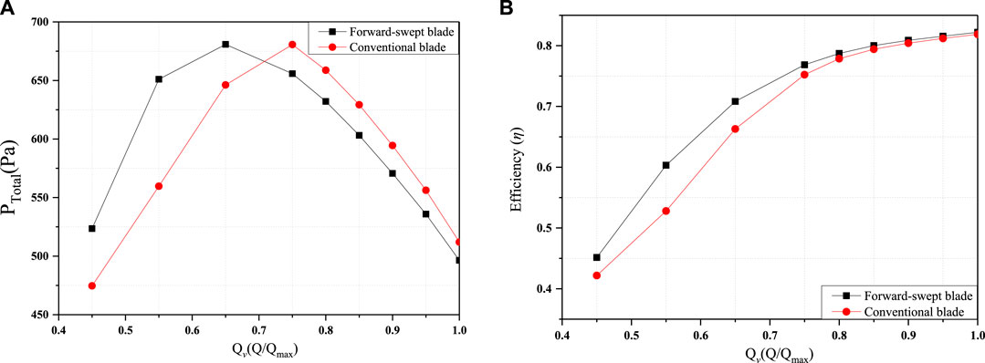
FIGURE 11. Forward-swept blade characteristic curves: (A)
To further study the internal flow conditions of forward-swept and traditional blades under low flow conditions, the section flow pattern method (Liang et al., 2021) is used to observe the internal flow field of different regions, and the streamlines from five characteristic sections are selected. As shown in Figure 12, both traditional blades and forward-swept blades suffer corner separation at 0.65
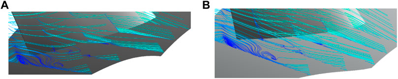
FIGURE 12. Streamline at the root: (A) traditional blade and (B) forward-swept blade.
Figure 13 shows that there are vortices at the tip of the traditional blade. As the air flow contacts the blade, a vortex forms at the tip of the blade around the front edge of the blade suction. With the gradual development of the mainstream in the channel, this vortex interacts with the wake after leaving the blade to form two vortices with opposite rotation directions. As a low-energy fluid, the rotation of the vortex itself will cause energy dissipation and affect the surrounding fluid, resulting in a decrease in the mainstream velocity at the blade tip and the deterioration of the flow state. The forward-swept blade makes the tip of the blade work on the fluid in advance, making the flow more stable. As shown in Figure 13, there is no wake vortex at the trailing edge, and only a small-scale vortex is formed at the leading edge. After the forward-sweep modification of the equal–variable circulation design, the flow at the blade tip under low flow conditions can be optimized. That is, the energy dissipation at the blade tip is reduced and the stable operation range of the fan is improved.
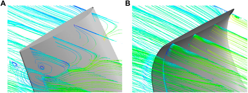
FIGURE 13. Streamline at the blade tips: (A) traditional blade and (B) forward-swept blade.
Figure 14 shows the radial distribution of the axial velocity at the exit of the impeller with the forward-swept blades and conventional blades designed by the equal–variable circulation method at
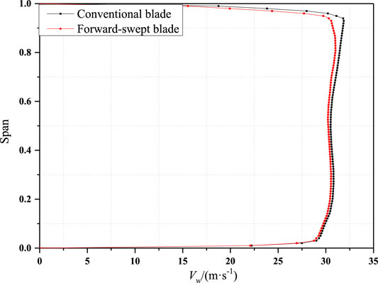
FIGURE 14. Axial velocity comparison of forward-swept blades and conventional blades at the exit.
5 Conclusion
1) The equal–variable circulation design method can be applied for the design of forward-swept blades and conventional blades. The efficiency of equal–variable circulation design blades is basically the same as the blades from the equal and variable design methods, but the total pressure can be increased by 4%. The equal–variable circulation designed blades have a more stable axial velocity from the root to the tip of the blade, a greater axial velocity, and a stronger circulation capacity. The axial velocity of the equal–variable circulation designed blades is higher than that of the other two blade types. The equal–variable circulation design effectively increases the chord length of each section of the blade. Thus, combining the advantages of the equal circulation design and the variable circulation design effectively enhances the blade’s performance.
2) Different forward-sweep heights will have different impacts on the aerodynamic performance of the blade. There is an optimal forward-sweep height that gives the best aerodynamic performance. In this study, a forward sweep starting at 60% of the blade height with an angle of 20° gives the optimum efficiency.
3) The conventional blades designed by the equal–variable circulation design method achieve higher total pressures when the flow rate is larger. The forward-swept blades designed by the equal–variable circulation design method have higher efficiency and a wider stable operating area. As the flow rate decreases, the traditional blade will produce large shedding vortices at the blade tip. The forward-swept blade can effectively inhibit the formation of these vortices and improve the efficiency of turbomachinery. The change in the blade’s center-of-gravity stacking line may optimize the flow at the tip of the blade while increasing the efficiency and optimizing the operating area.
Data Availability Statement
The original contributions presented in the study are included in the article/Supplementary Material; further inquiries can be directed to the corresponding author.
Author Contributions
SL, SW, YL, and ZZ provided experimental ideas and theoretical guidance. CS provided language guidance and writing guidance. All authors contributed to the article and approved the submitted version.
Funding
This work was supported by the National Natural Science Foundation of China (Grant No. 51776217).
Conflict of Interest
Author SL was employed by the company Shandong Jirong Thermal Technology Co., Ltd.; author SW was employed by the company China National Nuclear Power Operations Management Co., Ltd.
The remaining authors declare that the research was conducted in the absence of any commercial or financial relationships that could be construed as a potential conflict of interest.
Publisher’s Note
All claims expressed in this article are solely those of the authors and do not necessarily represent those of their affiliated organizations, or those of the publisher, the editors, and the reviewers. Any product that may be evaluated in this article, or claim that may be made by its manufacturer, is not guaranteed or endorsed by the publisher.
References
Adjei, R. A., Wang, W., and Liu, Y. (2019). Aerodynamic Design Optimization of an Axial Flow Compressor Stator Using Parameterized Free-form Deformation. J. Eng. Gas Turbines Power 141 (10), 101015. doi:10.1115/1.4044692
Burguburu, S. p., Toussaint, C., Bonhomme, C., and Leroy, G. (2004). Numerical Optimization of Turbomachinery Bladings. J. Turbomach. 126 (1), 91–100. doi:10.1115/1.1645869
Chen, N. X., Zhang, H. W., Du, H., Xu, Y. J., and Huang, W. G. (2005). Effect of Maximum Camber Location on Aerodynamics Performance of Transonic Compressor Blades. Proc. ASME Turbo Expo 6, 1117–1125. doi:10.1115/GT2005-68541
Cho, C.-h., Cho, S.-y., and Kim, C. (2009). Development of an Axial-type Fan with an Optimization Method. Front. Energ. Power Eng. China 3 (4), 414–422. doi:10.1007/s11708-009-0038-5
Gallimore, S. J., Bolger, J. J., Cumpsty, N. A., Taylor, M. J., Wright, P. I., and Place, J. M. M. (2002). The Use of Sweep and Dihedral in Multistage Axial Flow Compressor Blading-Part I: University Research and Methods Development. ASME Turbo Expo. Power Land, Sea, Air 124 (4), 521–532. doi:10.1115/1.1507333
Hassan Saeed, H. A., Nagib Elmekawy, A. M., and Kassab, S. Z. (2019). Numerical Study of Improving Savonius Turbine Power Coefficient by Various Blade Shapes. Alexandria Eng. J. 58 (2), 429–441. doi:10.1016/j.aej.2019.03.005
Hongpeng, L., Yu, W., Rujing, Y., Peng, X., and Qing, W. (2020). Influence of the Modification of Asymmetric Trailing-Edge Thickness on the Aerodynamic Performance of a Wind Turbine Airfoil. Renew. Energ. 147, 1623–1631. doi:10.1016/j.renene.2019.09.073
Idahosa, U., Golubev, V. V., and Balabanov, V. O. (2008). An Automated Optimal Design of a Fan Blade Using an Integrated CFD/MDO Computer Environment. Eng. Appl. Comput. Fluid Mech. 2 (2), 141–154. doi:10.1080/19942060.2008.11015217
Jang, C. M., and Kim, K. Y. (2007). Applications of Numerical Optimization Techniques to Design of Axial Compressor Blades. J. Aerospace Power 22 (004), 645–652. doi:10.1016/S1001-6058(07)60030-4
Lazari, A., and Cattanei, A. (2014). Design of Off-Statistics Axial-Flow Fans by Means of Vortex Law Optimization. J. Therm. Sci. 23 (6), 505–515. doi:10.1007/s11630-014-0735-1
Liang, D., Li, Y., Zhou, Z., Wiśniewski, P., and Dykas, S. (2021). Structure and Topology Analysis of Separated Vortex in Forward-Swept Blade. Front. Energ. Res. 9, 693596. doi:10.3389/fenrg.2021.693596
Pascu, M., Miclea, M., Epple, P., Delgado, A., and Durst, F. (2009). Analytical and Numerical Investigation of the Optimum Pressure Distribution along a Low-Pressure Axial Fan Blade. Proc. Inst. Mech. Eng. C: J. Mech. Eng. Sci. 1989-1996 (vols 203-210) 223 (C3), 643–657. doi:10.1243/09544062JMES1023
Peng, K., Fan, D., Yang, F., Fu, Q., and Li, Y. (2013). Active Generalized Predictive Control of Turbine Tip Clearance for Aero-Engines. Chin. J. Aeronautics 26 (5), 1147–1155. doi:10.1016/j.cja.2013.07.005
Place, J. M. M., and Cumpsty, N. A. (1998). Discussion: "Comparison of Sweep and Dihedral Effects on Compressor Cascade Performance" (Sasaki, T., and Breugelmans, F., 1998, ASME J. Turbomach., 120, Pp. 454-463). J. Turbomach. 120 (3), 463–464. doi:10.1115/1.2841739
Rehman, S., Alhems, L., and Rafique, M. (2018). Horizontal Axis Wind Turbine Blade Design Methodologies for Efficiency Enhancement-A Review. Energies 11 (3), 506. doi:10.3390/en11030506
Sogukpinar, H. (2018). The Effects of NACA 0012 Airfoil Modification on Aerodynamic Performance Improvement and Obtaining High Lift Coefficient and post-stall Airfoil. Turkish Phys. Soc. 33rd Int. Phys. Congress (Tps33) 1935, 020001. doi:10.1063/1.5025955
Sor̸ensen, D. N., and Sor̸ensen, J. N. (2000). Toward Improved Rotor-Only Axial Fans-Part I: A Numerically Efficient Aerodynamic Model for Arbitrary Vortex Flow. J. Fluids Eng. 122 (2), 318–323. doi:10.1115/1.483275
Sor̸ensen, D. N., Thompson, M. C., and Sor̸ensen, J. N. (2000). Toward Improved Rotor-Only Axial Fans-Part II: Design Optimization for Maximum Efficiency. J. Fluids Eng. 122 (2), 324–329. doi:10.1115/1.483260
Sreekanth, M., Sivakumar, R., Sai Santosh Pavan Kumar, M., Karunamurthy, K., Shyam Kumar, M., and Harish, R. (2021). Regenerative Flow Pumps, Blowers and Compressors - A Review. Proc. Inst. Mech. Eng. A: J. Power Energ., 095765092110181. doi:10.1177/09576509211018118
Wadia, A. R., Szucs, P. N., and Crall, D. W. (1998). Inner Workings of Aerodynamic Sweep. J. Turbomach. 120 (4), 671–682. doi:10.1115/1.2841776
Yang, D. U. (2008). Internal Flow Mechanism and Experimental Research of Low Pressure Axial Fan with Forward-Skewed Blades. J. Hydrodynamics, Ser. B 20 (3), 299–305. doi:10.1016/S1001-6058(08)60061-X
Keywords: axial turbomachinery, equal–variable circulation method, forward sweep, aerodynamic performance, blade tip
Citation: Liang D, Song C, Liang S, Wang S, Li Y and Zhou Z (2021) Design and Performance Analysis of Blades Based on the Equal–Variable Circulation Method. Front. Energy Res. 9:790622. doi: 10.3389/fenrg.2021.790622
Received: 07 October 2021; Accepted: 22 October 2021;
Published: 18 November 2021.
Edited by:
Hongbing Ding, Tianjin University, ChinaReviewed by:
Xu Han, North China Electric Power University, ChinaJiang Bian, China University of Petroleum (East China), China
Copyright © 2021 Liang, Song, Liang, Wang, Li and Zhou. This is an open-access article distributed under the terms of the Creative Commons Attribution License (CC BY). The use, distribution or reproduction in other forums is permitted, provided the original author(s) and the copyright owner(s) are credited and that the original publication in this journal is cited, in accordance with accepted academic practice. No use, distribution or reproduction is permitted which does not comply with these terms.
*Correspondence: Z. Zhou, enpud3RAMTYzLmNvbQ==