 Liansong Xiong
 Binbing Wu
 Xiaokang Liu
 Liancheng Xiu1,5
- 1School of Automation, Nanjing Institute of Technology, Nanjing, China
- 2Key Laboratory of Control of Power Transmission and Conversion, Shanghai Jiao Tong University, Shanghai, China
- 3School of Electrical Engineering, Xinjiang University, Urumqi, China
- 4Department of Electronics, Information and Bioengineering, Politecnico di Milano, Milan, Italy
- 5School of Electrical Engineering and Automation, Wuhan University, Wuhan, China
- 6State Grid Jiangsu Maintenance Company, Jiangsu, China
Asymmetrical working conditions of the utility grid introduce the large-amplitude negative-sequence component to the output current of the voltage source converter (VSC), causing power semiconductor devices to suffer from thermal fatigue and thermal damage. Though the conventional phase-locked loop (PLL) based voltage oriented control (VOC) solution can suppress the steady-state negative-sequence current effectively, it has a weak suppression ability of transient overload current, and even aggravates the transient current asymmetry and causes more severe transient impact to the VSC. This paper first analyzes the transient performance of the conventional VOC strategy, especially its dynamic response time and the main factors for performance limitation. On this basis, the PLL-free VOC strategy for VSCs tied to unbalanced grids is proposed, and its critical parts, namely, the reference current calculation and the fast detection of the grid voltage sequence components, are implemented. Besides, to improve the frequency adaptability, a high-performance grid frequency detection strategy is developed based on the difference-frequency phase caused by the frequency variation. Finally, experiments are performed to verify the effectiveness and advancement of the proposed method. Specifically, the results proved the rapidity, accuracy, and frequency adaptability of the proposed method in suppressing the VSC negative-sequence current, both in transient and steady-state conditions.
1 Introduction
With the bulk application of wind power, photovoltaic power, energy storage, flexible AC transmission systems, and other devices in the power systems, there has been an increasing proportion and importance of grid-tied voltage-source-converters (VSCs), Xiong et al. (2020a); Zhang K. et al. (2021). At the same time, the overhead power lines used for distributed power collection are scattered in a wide geographic space, causing high susceptibility of the utility grids to various asymmetric disturbances and requiring the grid-tied VSCs to be equipped with the ability to suppress unbalanced disturbances Xiu et al. (2021a). Different from the electromechanical equipment with excellent overload performance and strong resistance to faulty impact, VSCs with the semiconductor device as the core have weak overload capacity. Long-term overload operation will cause equipment performance degradation or even complete damage, Xiu et al. (2021b). Therefore, it is necessary to detect the amplitude, phase, and frequency information of the main electrical components in the transient process as quickly as possible and use advanced VSC control strategies to suppress random disturbances and various faults, so as to effectively reduce the time and intensity of the VSC subjected to the transient impact, ensure that the VSC can enter the new stable state quickly and safely, and improve the system reliability and security, Xiong et al. (2020b).
In recent years, many investigations have been performed on the detection and control strategies for the VSC system under unbalanced utility grid conditions. Wai et al. (2015) proposed a neural fuzzy network based online compensation method for suppressing the three-phase unbalanced current on the grid side. In order to effectively suppress the negative impact of harmonics on the VSC control performance, Xiong et al. (2016c) compares the performance of two typical harmonic elimination algorithms, and lays out the basis for the optimal algorithm selection in engineering applications. Dedeoglu and Konstantopoulos (2018) extended the rotational coordinate frame and used two sets of dynamically changing reference frames to control the negative-sequence component, effectively suppressing the secondary fluctuation of the DC side voltage. In the aforementioned works, the VSC control is realized by making use of the phase-locked loop (PLL), which can generate inaccurate or delayed phase information under the event of unbalanced utility grid faults, especially the single synchronous reference frame (SRF) PLL, leading to reduced power transmission efficiency of the grid-tied VSCs, or even worse, their inability to work. To this end, Rodriguez et al. (2007) proposes a decoupled double SRF PLL (DDSRF-PLL) to completely eliminate the detection errors of conventional single SRF PLL, yet leading to the complex control loop design and significantly long response time. In order to simplify the control system structure, Chaudhary et al. (2012) utilized the second-order generalized integrator based PLL (SOGI-PLL) to obtain the real-time phase of the unbalanced utility grid. However, Zhang C. et al. (2021) pointed out the concealed stability issue of SOGI-PLLs arising from different implementations of the frequency-feedback-path. To avoid the negative-sequence component from affecting the accuracy, stability and rapidity of the PLL, Li Z. et al. (2018) improved the conventional SRF-PLL, yet the detection time is still too long and the VSC will still suffer from the transient overload current for a long time. To achieve the desired multi-objective control and the optimal overall performance, Lin et al. (2019) introduced the particle swarm algorithm to further optimize the control parameters of the VSC system. Besides that, in order to increase the adaptability to the non-ideal grid conditions, Mishra and Lal (2021) proposed an enhanced control method to suppress the effect of distorted grid voltage.
In addition to the continuous improvement of the various PLL methods, there are several advanced detection technologies and control strategies trying to directly remove the PLLs. Xiong et al. (2016b) was the first to realize the high-performance amplitude and phase detection without PLL, yet it cannot adapt to the working condition of grid frequency fluctuation or provide the real-time grid frequency information. Wu et al. (2020b) proposed a fast phase detection scheme and successfully extracted the real-time phase of the fundamental-frequency positive-sequence component of the utility voltage under unbalanced and distorted conditions. In order to realize a PLL-free scheme in the VSC system, Nian et al. (2016) achieved the suppression of negative-sequence current under unbalanced utility grids, yet this scheme requires extensive dynamic response time as long as 4 grid cycles in the presence of grid frequency fluctuations. Li L. et al. (2018) successfully developed the PLL-free direct power control strategy to compensate for the unbalanced current generated by the unbalanced utility grids. Cheng et al. (2020) realized the PLL-free control of the converter in the unbalanced grid, yet it is still limited to the condition with insignificant grid frequency fluctuations. Further, Wu et al. (2020b) designed an independent control system for VSC power transmission, which can deal with the power fluctuation issue under unbalanced utility grids.
In this paper, a PLL-free VOC strategy for VSCs tied to unbalanced grids, which can minimize the overload current and hence the time and intensity of the VSC suffering from its impact, is developed. In Section 2, the basic PLL based VOC strategy for the grid-tied VSC is introduced, and its technical challenges are analyzed. In Section 3, the PLL-free VOC strategy of the grid-tied VSC is designed, and the command current calculation and the fast detection method of grid voltage sequence components are also presented. In Section 4, a fast frequency detection scheme based on the detected difference-frequency phase is developed, enhancing the frequency adaptability performance of the PLL-free VOC strategy. Finally, the effectiveness and advancement of the proposed scheme are verified in Section 5.
2 PLL-Based VOC Strategy and Its Technical Challenges
2.1 Basic Principle
The main circuit topology of the grid-tied VSC is shown in Figure 1, where R, L, and C are the equivalent series resistance, inductance, and DC-side capacitance of the VSC system; Udc and Idc are the DC-side capacitor voltage and DC input current of the VSC, respectively; uabc and vabc are the three-phase grid voltage and the output voltage of the VSC system, respectively.
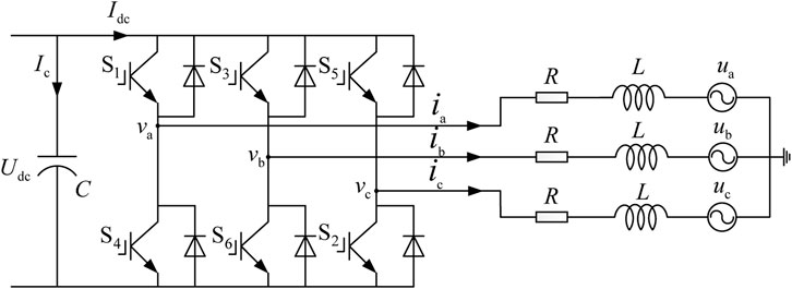
FIGURE 1. System topology of the grid-tied VSC.
When the utility grid is operating in the ideal state, the three-phase grid voltage is balanced, and only the positive-sequence component exists. In this case, the grid voltage can be formulated as
where
To maintain synchronous operation of the VSC w.r.t. the utility grid, it is necessary to primarily obtain the phase (θ) and frequency (ω) information of the grid voltage, based on which the output voltage and power of the VSC can be adjusted, thereby achieving stable grid-tied operation. To this end, the PLL with the structure shown in Figure 2 is usually used, where kp and ki are the proportional and integral coefficients of the PI controller, respectively, mod is the modulo operation that calculates the remainder after division, and the abc/dq transformation matrix is given by
Since θ is time-variant (see Eq. 2), the PLL dynamically adjusts its output phase through a PI controller-based closed-loop control system, and tracks the phase of the grid voltage in real time by making

FIGURE 2. Structure of the traditional closed-loop PLL.
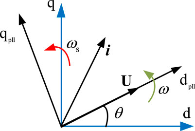
FIGURE 3. Grid voltage and current phasors in the PLL-based reference system.
Using the transformation matrix in the PLL and the PLL output phase, the grid voltage in Eq. 1 can be converted into
According to Eq. 4, when the phase is locked, the PLL-based dq-coordinate frame has its d-axis aligned with the grid voltage vector, and a null q-axis component. At this time, the dq-frame is grid voltage oriented.
In such a frame, the active power and reactive power transmitted from the VSC to the grid can be calculated as
If the power loss of the VSC system is ignored, the active power output by the VSC is equal to that on the DC-side, namely
In the grid voltage-oriented dq-frame, the active power and reactive power output by the VSC are only proportional to their d- and q-axis current components, and the d-axis current is proportional to the DC-side voltage of the VSC. Hence, the d- and q-axis current components of the VSC can be controlled separately, by adjusting the DC capacitor voltage or the reactive power output by the VSC. The relevant control methods are only valid in the grid voltage-oriented dq-frame, and are referred to as the VOC strategies (see Figure 4).
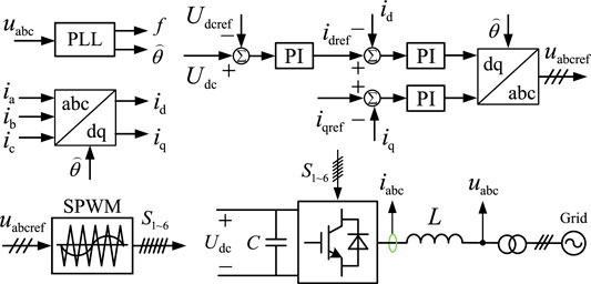
FIGURE 4. Basic sketch of the PLL based VOC strategy.
2.2 Dynamic Response Time
Preliminary assumptions are made prior to obtaining the dynamic response time of the PLL based VOC strategy. The PLL is a key component of the VOC strategy, and the dynamic responses of the capacitor voltage control and the current control, which are based on the output phase of the PLL, can be neglected due to their fast speeds. Therefore, the response time of the VOC strategy mainly depends on the PLL. The small-signal model of the PLL with single SRF for dynamic characteristics analysis is shown in Figure 5.
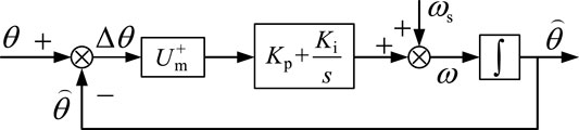
FIGURE 5. Small-signal model of the PLL with single SRF.
When the steady-state phase error of the PLL is negligible, we have
According to Figure 5, the closed-loop phase transfer function and the phase error transfer function can be expressed respectively as
where ζ is the damping factor and ωn is the natural frequency, and
In the under-damped state, the phase errors corresponding to the phase step and frequency step of the PLL can be respectively expressed as
where
Hence, the 2% dynamic response time ts and the system bandwidth ωb of the PLL based VOC strategy can be expressed as Freijedo et al. (2009), Wang and Wei Li (2011).
It can be seen from Eqs 15, 16 that the larger the damping factor ζ and natural frequency ωn, the larger the system bandwidth and the faster the response speed, and vice versa. In fact, the damping factor and natural frequency of the VOC strategy are determined by the proportional gain kp and the integral gain ki of the PLL’s PI controller. The larger these gain values, the higher the bandwidth, and the faster the response speed.
2.3 Technical Challenges
The measured signal inevitably contains various random noises, making it necessary to equip the system with anti-interference ability. With reference to Eq. 8, the PLL exhibits the low-pass filter (LPF) feature, hence the VOC strategy can partially suppress the detection error caused by the random noise and high-order harmonics. Under the common grid conditions of symmetrical operation, the low-order harmonics do not have large amplitudes, and the VOC strategy-based VSC system can obtain satisfactory dynamic performance and anti-noise ability by adjusting the proportional and integral parameters, Wu et al. (2020a); Xiong et al. (2016b). However, under the asymmetric disturbance conditions that can easily occur, electrical quantities are characterized by low-frequency harmonics with large amplitudes in the dq coordinate frame, especially the second harmonic. The basic principle is analyzed as follows.
According to the symmetrical component analysis, the three-phase unbalanced voltage can be decomposed into the positive-sequence, negative-sequence, and zero-sequence components. Without loss of generality, the influence of negative-sequence component on the VOC strategy is illustrated here as an example. The zero-sequence component can be analyzed similarly. Based on this assumptions, the three-phase asymmetrical grid voltage U can be expressed by the positive-sequence component U+ and the negative-sequence component U− as
where
Accordingly, in the dq coordinate frame of the PLL, the asymmetrical grid voltage shown in (17) will be transformed into
When the real time phase is locked by the PLL, i.e.,
According to Eqs 18, 19, the unbalanced grid voltage always has a double-frequency AC component with large amplitude in the dq coordinate frame, both during the transient and steady state. For the PLL system that achieves zero q-axis component as the target, the double-frequency component will have a significant impact on its synchronization performance and tracking error. For better accuracy of the output phase and frequency information, the system bandwidth must be significantly reduced in the unbalanced grid case to effectively suppress the double-frequency AC component, as shown in Figure 6. This can be achieved by reducing the proportional gain kp and the integral gain ki in the PI controller of the PLL; however, this improvement of system anti-interference ability substantially extends the dynamic response time of the VOC strategy. To address this issue, a variety of LPFs (see the purple region in Figure 2) have been proposed to suppress the negative effect of the double-frequency component. Since the filter is contained in the control loop, they are interacted in the dynamic control process, thus sharply increasing the system complexity, and making it difficult to effectively analyze and control the system dynamic performance. The most widely used SOGI-PLL and DDSRF-PLL solutions take nearly two grid cycles to return to the steady state, under the premise of working in their optimal states.
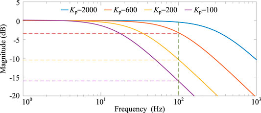
FIGURE 6. System bandwidth and anti-interference ability of the PLL.
It is obvious that a conflict is inevitable between the response speed (depending on the system bandwidth) and the anti-interference ability for a closed-loop dynamic control system, and thus, the art of compromise is needed for designing the PLL based VOC strategy. However, under severely unbalanced utility grid conditions, the more common result is that the two indicators have been both significantly jeopardized, making it difficult to achieve a satisfactory compromise for performance design. Since the root of such issues lies in the complex dynamic process introduced by the PLL, one solution would be adopting a PLL-free VOC scheme.
In this paper, a PLL-free VOC scheme is developed by using the constant-speed rotational coordinate frame to replace the traditional dq-coordinate frame of the PLL. To avoid the complex dynamic adjustment process of the PLL, this constant-speed rotational frame is coherent with the rotation speed of the grid voltage vector (i.e., the synchronous speed of the grid, ωs), ensuring that the electrical quantities are converted into constant values in this frame. The dq-axis components of the grid voltage no longer participate in the closed-loop control process, eliminating the dynamic loops used for phase and frequency measurement. Accordingly, the dynamic response speed of the VOC strategy can be greatly improved.
Figure 3 shows the dq-axis components of the grid voltage U in different dq frames. These quantities can be related as
Based on Eq. 20, the two coordinate frames can be converted through a linear transformation, and when the PLL is in steady state, φ = ϕ. Accordingly, there is no essential difference between the two frames; grid quantities merely have different projection results in corresponding coordinate frames. However, the dq-axis components of the grid voltage are invariant in the constant-speed rotational frame, yet involved in the complex dynamic process when using the rotational frame of the PLL. In the latter case, the dq-components exhibit complex time-variant behaviors, and only transition to the steady state after a long time, restricting the performance of subsequent VSC voltage and current control, causing the VSC equipment to withstand a long-term overload impact under severe asymmetric disturbances, and introducing a serious threat to the reliability and safety of the equipment.
3 Implementation of PLL-Free VOC Strategy for VSCs Tied to Unbalanced Grids
3.1 Calculation of VSC Control Reference Values
Since the circuit topology of the grid-tied VSC (see Figure 1) has no neutral point or neutral line, the effect of the zero-sequence component of the VSC system can be neglected. Therefore, in the PLL-free constant-speed rotational coordinate frame, the positive- and negative-sequence circuits of the VSC system can be described as
The instantaneous power at the VSC grid-side is
From Eq. 22, the active and reactive powers output by the VSC system, under the unbalanced grid voltage condition, include not only the constant power components P0 and Q0 under the balanced condition, but also the double-frequency oscillatory components Psin, Pcos, Qsin, and Qcos, with the expression of
In order to suppress the power fluctuations, we have
where the subscript ref represents the reference value of the corresponding physical quantity.
By substituting Eq. 24 into Eq. 23, the VSC output current reference when the power oscillation is suppressed can be obtained, yielding
where
The core component of the VSC system, i.e., the semiconductor power device, has extremely weak overcurrent capability and high sensitivity to temperature rise. Hence, under severely unbalanced utility grid conditions, the negative-sequence current is usually suppressed first to ensure that the current amplitude of each phase is balanced and not overloaded, avoiding the overcurrent-related thermal fatigue and thermal damage of power semiconductor devices. Accordingly, the negative-sequence current and power commands of the VSC are given by
By substituting Eq. 27 into Eq. 23, the positive-sequence current command of the VSC when the negative-sequence current is suppressed can obtained as
where
In general, to achieve DC-side voltage stability of the grid-tied VSC, the VOC strategy uses a capacitor voltage control loop to calculate the active power command of the VSC, yielding
where KPP and KPI are the proportional and integral gains of the outer voltage loop, respectively.
At the same time, in order to achieve unity power factor of the grid-tied operation, the reactive power command of the VSC is set to 0, i.e., Qref = 0. However, when the reactive power is required to be provided by the VSC, its reference value can be set according to the specification. When the VSC is required to actively support the stable operation of the grid voltage, the reactive power command Qref is usually calculated by an AC-side voltage Uac control loop, namely
where KQP and KQI are the proportional and integral gains of the outer AC voltage loop, respectively.
3.2 Grid Voltage Sequence Component Detection
When calculating the VSC output current command according to Eqs 25, 28, it is necessary to first detect the sequence components of the unbalanced grid voltage. To this end, this paper resorts to the fast open-loop detection algorithm proposed by Xiong et al. (2016b) and Xiu et al. (2021a), and uses the grid voltage U and its orthogonal component U⊥ to directly extract the sequence components in the stationary coordinate frame. This gives
where
Similar to the grid voltage U, which is composed of the positive-sequence component U+ and the negative-sequence component U−, the orthogonal voltage U⊥ is composed of the pertinent orthogonal components
The grid voltage U in the stationary coordinate frame can be obtained through real-time detection, and its pertinent orthogonal voltage U⊥ is generally obtained through the differential method or the delay method; these methods are subjected to high random noise amplification or long response time. To improve the response speed and anti-noise ability, the fast and accurate orthogonal signal generator (OSG) scheme proposed by Xiong et al. (2016a) is chosen here. This gives
where Ts is the sampling period, k is the discrete time step, and K is the scaling factor that takes a positive integer. In this paper, K is chosen to be 5.
3.3 PLL-Free VOC Strategy
Figure 7 shows the proposed PLL-Free VOC strategy for VSCs tied to unbalanced grids. The strategy mainly includes a constant-speed rotational coordinate frame block, a grid voltage sequence component measurement block, a VSC output current transformation block, a DC-side capacitor voltage control block, VSC output current command calculation blocks, a VSC output current control block, and a PWM signal generation block.
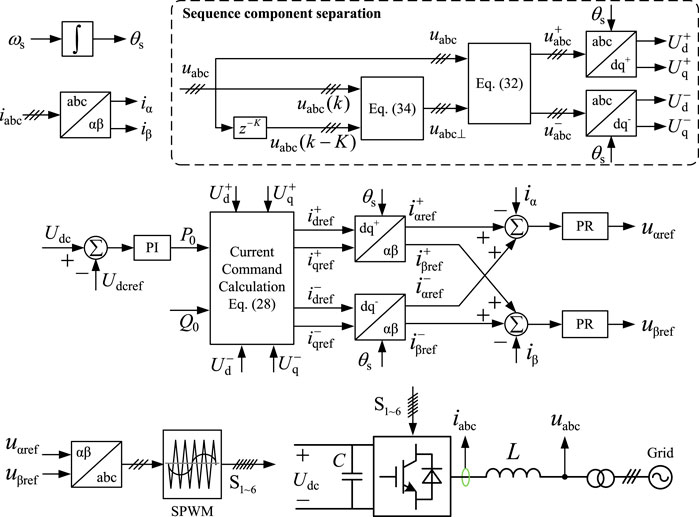
FIGURE 7. Proposed PLL-free VOC strategy for VSCs tied to unbalanced grids.
Unlike the basic VOC strategy (see Figure 4), the voltage and current are here formulated, measured, calculated and controlled in the constant-speed rotational coordinate frame with the proposed control strategy, which completely eliminates the PLL and its complex dynamic adjustments. This helps to significantly improve the control speed of the VSC output current, suppress the overload of the output current, and minimize the time and intensity of the overcurrent impact on the VSC.
To enable the fast and accurate tracking of the current command for the grid-tied VSC, the PLL-Free VOC strategy proposed in this paper adopts the inner current loop control based on the proportional resonant (PR) controller, Cheng et al. (2020), whose tranfer function writes
where ωc is the bandwidth parameter of the PR controller with a typical value of 5–15 rad/s; Kpk and Kik are the primary and secondary resonance coefficients, respectively, Cheng et al. (2020), and:
The introduction of the PR controller enables the direct, real-time implementation of the current control in the stationary coordinate frame, thereby eliminating the coordinate frame transformation process related to the sequence component extraction of the grid current, and reducing the computation burden of the control strategy. Besides, to further reduce the number of control loops and the corresponding calculation amount, this paper makes use of the zero-sequence current-free characteristic of the VSC (see Figure 1) to design the current control algorithm (see Figure 7) in the αβ coordinate frame. The transformation from the abc coordinate frame to the αβ frame is given by
To simplify the analysis of current loop control parameters and their adaptability to frequency fluctuations, the influence of the outer capacitor voltage loop is neglected, since the bandwidth of the inner current loop is usually 5 times larger than that of the outer loop. Accordingly, the VSC system can be described by the equivalent block diagram in Figure 8, where Kpwm(s) is the transfer function of the pulse width modulation (PWM) enabled VSC circuit, expressed as the ratio of its output AC voltage to the input DC voltage. In the digital realization of the PWM block, a delay of one sampling period Ts is caused by the fixed-time sampling and calculation. Besides, the modulation signal needs to remain unchanged in the next sampling period when it is loaded, and this process can be described by a zero-order holder (ZOH) with the average delay of Ts/2, Pan et al. (2014). Therefore,
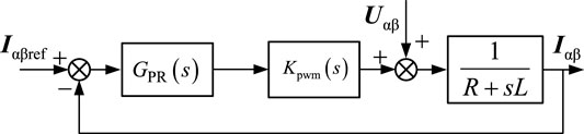
FIGURE 8. Equivalent block diagram of VSC system.
Accordingly, after adopting the PR controller, the output voltage of the VSC system can be described as
The open-loop transfer function of the current control loop of the VSC system is
The Bode diagram of the system open-loop transfer function can be obtained (see Figure 9), by substituting the VSC system parameters (see Table 1) into Eq. 40. The current loop has a gain of 37 dB at the synchronous frequency (50 Hz), indicating that the PR controller has a sufficient gain to adjust the current command value without difference. When the grid frequency fluctuates within ±0.2 Hz, the lowest resonance gain is 35.5 dB, indicating efficient suppression of the negative-sequence current via the PR controller when the grid frequency fluctuates within the range limited by the grid code. Besides, the phase of the open-loop current transfer function at the resonant frequency is 0°, and the phase response is always maintained between −90° and 90°. This proves that the PLL-free VOC strategy proposed in this paper can effectively ensure the VSC system stability.
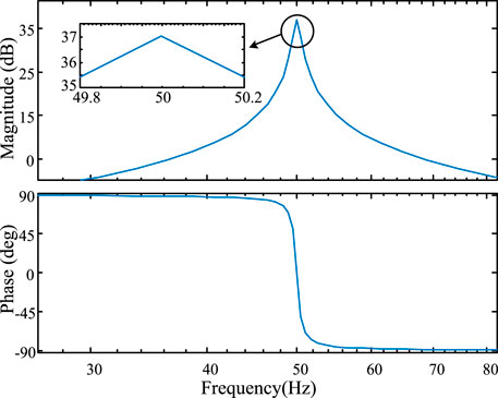
FIGURE 9. Bode diagram of VSC system open-loop transfer function.

TABLE 1. System parameters.
4 Frequency Adaptive Scheme
Based on the Bode diagram in Figure 9, when the grid frequency fluctuates within the range limited by the grid code, the PR controller can effectively suppress the negative-sequence current, yet ensuring the VSC system stability. However, under extreme fault disturbances, the grid voltage is severely unbalanced, and the grid frequency may also exceed the range limited by the grid code. At this time, in the absence of a frequency adaptive strategy, the current command tracking ability of the VOC strategy will be sharply reduced, thereby weakening the overcurrent suppression capability of the VSC. Focusing on this issue, this paper proposes a frequency adaptive strategy based on the frequency detection method in Xiu et al. (2021b).
First, the open-loop phase detection method in Xiong et al. (2016b) is used to obtain the real-time phase of the positive-sequence component of the grid voltage. The corresponding expression can be derived from Eq. 2, yielding
where ϕ0 is the angle between the grid voltage vector and the d-axis of the constant-speed rotational coordinate frame, i.e., the initial phase of the grid voltage in the coordinate frame. Analogous to the initial phase in Eq. 2, here ϕ0 must satisfy
It can be seen that when the grid frequency changes, the initial phase of the grid voltage is no longer invariant in the constant-speed rotational coordinate frame, but changing continuously over time.
Besides, when the grid frequency changes, the dq-axis components of the positive-sequence component of the grid voltage in the constant-speed rotational coordinate frame are
Accordingly,
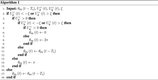
where θex is the extra phase introduced to meet the condition
However, direct calculation of grid phase by Eqs 44, 45 may lead to its instability, due to the sudden transition of extra phase at the specific boundaries. The presence of random noise can cause jitters in the detected phase. To solve this issue, the extra phase
To further reveal the relationship between the frequency fluctuation and the real-time phase θ, θ in Eq. 41 can be decomposed into the synchronous-frequency component θs and the difference-frequency component θd, namely
where
Since ϕ is unknown, the difference-frequency phase θd cannot be directly calculated by Eq. 48. However Eq. 48 shows that the difference-frequency phase θd has a linear relationship with the grid frequency deviation, namely, increasing (or decreasing) the frequency deviation can correspondingly increase (or decrease) the difference-frequency phase. Therefore, a closed-loop system can be designed to obtain the frequency
When the difference-frequency phase has been tracked (i.e.,
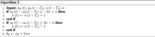
The successful implementation of this frequency detection algorithm depends on whether the difference-frequency phase θd can be accurately obtained. From Eqs 42, 48, we have
where n (with an initial value 0) is a time-variant integer number for phase compensation, with the aim to generate a continuous θd over time starting from the result of ϕ0 (calculated via Eq. 44 and Algorithm 1 and limited in 2π). Specifically, the difference between
Based on the above analysis, the frequency adaptive strategy with real-time frequency detection ability is obtained, as shown in Figure 10.
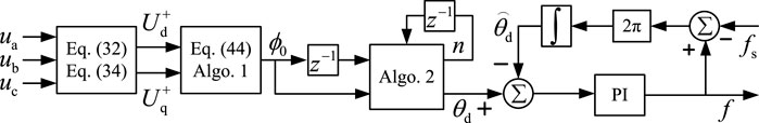
FIGURE 10. Proposed frequency adaptive strategy.
5 Experiment Results
In order to prove the feasibility and advancement of the proposed strategy, experiments have been carried out under the condition that the power grid changes from symmetrical operation to asymmetrical operation. The main parameters of the VSC system are collected in Table 1.
5.1 Constant Grid Frequency Scenario
In the first study, the grid is disturbed while the grid frequency is kept the same (see Figure 11A), and the performance of the proposed PLL-free VOC strategy is compared versus two scenarios, i.e., without the negative-sequence current suppression algorithm, and when the negative-sequence current is suppressed based on the SOGI-PLL. The pertinent experiment results are shown in Figure 11.
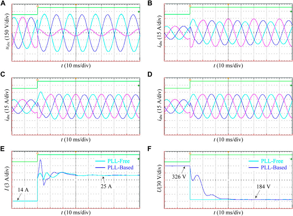
FIGURE 11. Experiment results with constant frequency. (A) Three-phase grid voltage. (B–D) VSC output current in the absence of negative-sequence current suppression algorithm, with the SOGI-PLL based negative-sequence current suppression, and with the proposed PLL-free VOC strategy, respectively. (E) RMS values of the VSC output current. (F) Amplitude detection result of the positive-sequence component of the grid voltage.
After being disturbed, the utility grid changes from the symmetrical operation to the asymmetrical operation (see Figure 11A), where the voltage becomes severely unbalanced. In the absence of proper measures, this asymmetry inevitably leads to serious imbalance also in the output current of the grid-tied VSC, resulting in a significant increase in the current amplitude of some phases of the VSC, as shown in Figure 11B. As a result, the VSC temperature rises sharply until the equipment damages due to severe overcurrent, or the VSC is automatically disconnected by the overcurrent/overheat protection.
After using the SOGI-PLL based negative-sequence current suppression strategy, the VSC avoids the impact of long-term asymmetric current, as shown in Figure 11C. Though the VSC output current has been significantly improved w.r.t. the previous case, the adopted SOGI-PLL algorithm causes a long dynamic adjustment process (about 25 ms) of the VOC strategy, and the transient has a large overshoot, causing the VSC to undergo a long-term, severe current overload condition. Indeed, the maximum VSC current during the transient even exceeded that with no negative-sequence current suppression. Hence, this SOGI-PLL based method, though effectively improves the steady-state current quality of the VSC, exhibits a poor transient adjustment ability. At this time, the VSC still suffers from the severe transient current impact that threatens the equipment performance, reliability, and safety.
When the proposed PLL-free VOC strategy is used, the VSC connected to the unbalanced grid nearly always outputs three-phase symmetrical current waveforms, as shown in Figure 11D. This solves both the steady-state and transient unbalance issues; the VSC completely avoids the overcurrent and overheating impacts caused by the negative-sequence current, and maintains remarkable power quality. The key reason lies in the complete removal of the PLL block that requires a complex dynamic process. The relevant physical quantities are directly measured, calculated, and controlled in the constant-speed rotational coordinate frame, requiring no longer the dynamic adjustment process, and maintaining relatively constant even during the transient. To further prove this, amplitudes of the VSC output currents are provided and compared in Figure 11E. The amplitude variation range has been obviously reduced from 7 A (with the SOGI-PLL based strategy) to less than 1 A (with the PLL-free VOC strategy), and the response time has been reduced to less than 10 ms. Also, the detection speed of the positive-sequence component of the grid voltage has be significantly improved, as shown in Figure 11F. Though different dq coordinate frames (and thus, inconsistent dq-axis components) are used by these strategies, they provide coherent magnitude results of the positive-sequence component of the grid voltage, with the exception of calculation times.
5.2 Grid Frequency Fluctuation Scenario
To test the frequency adaptability of the proposed method, the above experiments are performed under the condition of sudden frequency change of the utility grid, and the results are shown in Figure 12. After the asymmetric disturbance, the grid voltage frequency is changed from 50 to 51 Hz, as shown in Figure 12A. Under the influence of such large frequency fluctuations, the waveform quality of the output current of the grid-tied VSC, if no measures are taken, will be severely reduced. When the SOGI-PLL based strategy is used, the grid frequency can be obtained within about 20 ms, as shown in Figure 12B, which is a longer time and leads to even worse transient current feature of the VSC compared to the previous constant-frequency condition. Even if better steady-state waveform quality of the VSC output current is obtained, the dynamic response time of the system is extended to nearly 80 ms, as shown in Figure 12C. Due to the complex dynamic tracking process of the PLL, a longer time is needed to dynamically track the amplitude, phase, and frequency of the grid voltage, due to the sudden frequency change in the grid frequency. Owing to the removal of the closed-loop detection structure, the proposed frequency detection method, which is critical for the frequency adaptability of the proposed PLL-free VOC strategy, can quickly and accurately track the grid voltage frequency; both the detection time and the transient overshoot are significantly improved compared to the SOGI-PLL, as shown in Figure 12B. Obviously, when the proposed strategy is adopted, the VSC maintains excellent control ability of the negative-sequence current, which is effectively suppressed in both the steady state and transient state. The control performance of the strategy is virtually unaffected by the frequency change, as shown in Figure 12D. Similarly, to intuitively observe the transient process, the VSC transient current amplitudes with the two strategies are compared in Figure 12E. After adopting the proposed strategy, the overshoot range of the transient current amplitude is reduced remarkably to less than 1 A, and the transient response time is reduced to 12 ms. The control ability of VSC under asymmetric utility grid conditions has been significantly improved. Similarly, the detection speed of the positive-sequence component of the grid voltage has also be significantly improved, which is achieved almost instantaneously, as shown in Figure 12F.
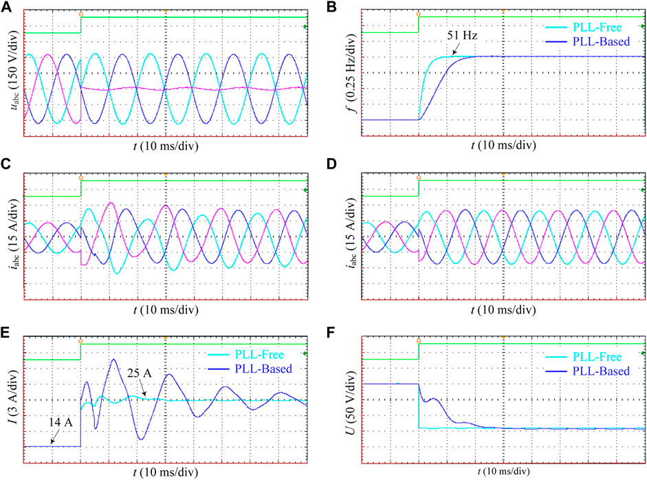
FIGURE 12. Experiment results with sudden frequency change. (A) Three-phase grid voltage. (B) Frequency detection result. (C,D) VSC output current with the SOGI-PLL based negative-sequence current suppression, and with the proposed PLL-free VOC strategy, respectively. (E) RMS values of the VSC output current. (F) Amplitude detection result of the positive-sequence component of the grid voltage.
6 Conclusion
This paper analyzes the technical challenges faced by the conventional PLL-based VOC strategy under unbalanced grid conditions, and proposes a PLL-free VOC strategy, along with its detailed implementation, for VSCs tied to unbalanced utility grids. Finally, experiments are conducted for verification. The main conclusions are as follows.
1. Under the severely asymmetrical working condition of the utility grid, the PLL is difficult to achieve a good compromise between the response speed and the anti-interference ability, due to the large amplitude of the double-frequency voltage component. Accordingly, the PLL-based VOC scheme is difficult to effectively suppress the negative-sequence current in the transient process, and even aggravates the transient current asymmetry and the resulting overcurrent problem, causing the power semiconductor devices to suffer from a significant thermal fatigue and damage for a long time.
2. The proposed PLL-free VOC strategy for VSCs tied to unbalanced grids completely removes the PLL and its complex dynamic adjustment process. The voltage and current required for VSC control are described, measured, calculated, and controlled in a constant-speed rotational coordinate frame. This significantly increases the control speed of the VSC output current and mitigates its overload, thereby minimizing the time and intensity of VSC suffering from overcurrent impact.
3. Unlike the conventional PLL method that measures the frequency first and then calculates the phase, the frequency detection method proposed in this paper dynamically tracks the grid frequency information based on the difference-frequency phase, which is caused by the frequency variation and can be quickly captured. Therefore, the VSC system can obtain the phase information necessary for the VOC strategy faster, and also accurately capture the grid frequency information, making the proposed PLL-free VOC strategy adaptive to large fluctuations of the grid frequency.
4. Experimental results prove the rapidity and accuracy of the proposed PLL-free VOC strategy in suppressing the VSC transient/steady-state negative-sequence current, and the effectiveness and superiority of the proposed frequency detection method. Also, the frequency adaptability of the proposed strategy is illustrated.
Data Availability Statement
The original contributions presented in the study are included in the article/supplementary material, further inquiries can be directed to the corresponding author.
Author Contributions
All the authors conceived and designed the study. LsX, BW, and LcX performed the simulation and experiment, and wrote the manuscript with the guidance from XL. BW and DW conceived and designed the experiments.
Funding
The work was supported in part by the Key Laboratory of Control of Power Transmission and Conversion (Shanghai Jiao Tong University), Ministry of Education (2018AC04).
Conflict of Interest
Author DW was employed by the State Grid Jiangsu Maintenance Company.
The remaining authors declare that the research was conducted in the absence of any commercial or financial relationships that could be construed as a potential conflict of interest.
Publisher’s Note
All claims expressed in this article are solely those of the authors and do not necessarily represent those of their affiliated organizations, or those of the publisher, the editors and the reviewers. Any product that may be evaluated in this article, or claim that may be made by its manufacturer, is not guaranteed or endorsed by the publisher.
References
Chaudhary, S. K., Teodorescu, R., Rodriguez, P., Kjaer, P. C., and Gole, A. M. (2012). Negative Sequence Current Control in Wind Power Plants with Vsc-Hvdc Connection. IEEE Trans. Sust. Energ. 3, 535–544. doi:10.1109/tste.2012.2191581
Cheng, P., Wu, C., Ma, J., and Blaabjerg, F. (2020). Coordinated Derived Current Control of DFIG’s RSC and GSC without PLL under Unbalanced Grid Voltage Conditions. IEEE Access 8, 64760–64769. doi:10.1109/ACCESS.2020.2984541
Dedeoglu, S., and Konstantopoulos, G. C. (2018). “Three-phase Grid-Connected Inverters Equipped with Nonlinear Current- Limiting Control,” in 2018 UKACC 12th International Conference on Control (CONTROL), 38–43. doi:10.1109/control.2018.8516764
Freijedo, F. D., Doval-Gandoy, J., Lopez, O., and Acha, E. (2009). Tuning of Phase-Locked Loops for Power Converters under Distorted Utility Conditions. IEEE Trans. Ind. Appl. 45, 2039–2047. doi:10.1109/TIA.2009.2031790
Li, L., Nian, H., Ding, L., and Zhou, B. (2018a). Direct Power Control of DFIG System without Phase-Locked Loop under Unbalanced and Harmonically Distorted Voltage. IEEE Trans. Energ. Convers. 33, 395–405. doi:10.1109/TEC.2017.2741473
Li, Z., Zang, C., Zeng, P., Yu, H., and Li, S. (2018b). Fully Distributed Hierarchical Control of Parallel Grid-Supporting Inverters in Islanded AC Microgrids. IEEE Trans. Ind. Inform. 14, 679–690. doi:10.1109/TII.2017.2749424
Lin, F.-J., Tan, K.-H., Lai, Y.-K., and Luo, W.-C. (2019). Intelligent PV Power System with Unbalanced Current Compensation Using CFNN-AMF. IEEE Trans. Power Electron. 34, 8588–8598. doi:10.1109/TPEL.2018.2888732
Mishra, M. K., and Lal, V. N. (2021). An Enhanced Control Strategy to Mitigate Grid Current Harmonics and Power Ripples of Grid-Tied PV System without PLL under Distorted Grid Voltages. IEEE J. Emerg. Sel. Top. Power Electron. doi:10.1109/JESTPE.2021.3107869
Nian, H., Cheng, P., and Zhu, Z. Q. (2016). Coordinated Direct Power Control of DFIG System without Phase-Locked Loop under Unbalanced Grid Voltage Conditions. IEEE Trans. Power Electron. 31, 2905–2918. doi:10.1109/TPEL.2015.2453127
Pan, D., Ruan, X., Bao, C., Li, W., and Wang, X. (2014). Capacitor-current-feedback Active Damping with Reduced Computation Delay for Improving Robustness of Lcl-type Grid-Connected Inverter. IEEE Trans. Power Electron. 29, 3414–3427. doi:10.1109/TPEL.2013.2279206
Rodriguez, P., Pou, J., Bergas, J., Candela, J. I., Burgos, R. P., and Boroyevich, D. (2007). Decoupled Double Synchronous Reference Frame Pll for Power Converters Control. IEEE Trans. Power Electron. 22, 584–592. doi:10.1109/TPEL.2006.890000
Wai, R.-J., Chen, M.-W., and Liu, Y.-K. (2015). Design of Adaptive Control and Fuzzy Neural Network Control for Single-Stage Boost Inverter. IEEE Trans. Ind. Electron. 62, 5434–5445. doi:10.1109/TIE.2015.2408571
Wang, Y. F., and Wei Li, Y. (2011). Analysis and Digital Implementation of Cascaded Delayed-Signal-Cancellation Pll. IEEE Trans. Power Electron. 26, 1067–1080. doi:10.1109/TPEL.2010.2091150
Wu, B., Chen, Y., and Xiong, L. (2020a). “Negative Sequence Component Compensation Strategy of Grid-Side Inverters without PLL,” in 2020 IEEE 9th International Power Electronics and Motion Control Conference (IPEMC2020-ECCE Asia), 2740–2743. doi:10.1109/IPEMC-ECCEAsia48364.2020.9368137
Wu, B., Tian, Y., Chen, Y., Abuduwayiti, X., and Xiong, L. (2020b). Virtual Frequency Construction-Based Vector Current Control for Grid-Tied Inverter under Imbalanced Voltage. IEEE Access 8, 199654–199663. doi:10.1109/ACCESS.2020.3030648
Xiong, L., Liu, X., Liu, Y., and Zhuo, F. (2020a). Modeling and Stability Issues of Voltage-Source Converter Dominated Power Systems: A Review. CSEE J. Power Energ. Syst., 1–18. doi:10.17775/CSEEJPES.2020.03590
Xiong, L., Liu, X., Zhao, C., and Zhuo, F. (2020b). A Fast and Robust Real-Time Detection Algorithm of Decaying DC Transient and Harmonic Components in Three-phase Systems. IEEE Trans. Power Electron. 35, 3332–3336. doi:10.1109/tpel.2019.2940891
Xiong, L., Zhuo, F., Wang, F., Liu, X., and Zhu, M. (2016a). A Fast Orthogonal Signal-Generation Algorithm Characterized by Noise Immunity and High Accuracy for Single-phase Grid. IEEE Trans. Power Electron. 31, 1847–1851. doi:10.1109/tpel.2015.2478155
Xiong, L., Zhuo, F., Wang, F., Liu, X., Zhu, M., and Yi, H. (2016b). A Novel Fast Open-Loop Phase Locking Scheme Based on Synchronous Reference Frame for Three-phase Non-ideal Power Grids. J. Power Electron. 16, 1513–1525. doi:10.6113/jpe.2016.16.4.1513
Xiong, L., Zhuo, F., Wang, F., Liu, X., Zhu, M., and Yi, H. (2016c). A Quantitative Evaluation and Comparison of Harmonic Elimination Algorithms Based on Moving Average Filter and Delayed Signal Cancellation in Phase Synchronization Applications. J. Power Electron. 16, 717–730. doi:10.6113/jpe.2016.16.2.717
Xiu, L., Du, Z., Li, M., Du, L., Hao, J., and Kang, Z. (2021a). A Practical and Fast Sequence Components Detection Scheme for Three-phase Unbalanced Grid Voltage. Int. J. Electr. Power Energ. Syst. 125, 106385. doi:10.1016/j.ijepes.2020.106385
Xiu, L., Du, Z., Wu, B., Li, G., Wang, D., and Song, H. (2021b). A Novel Adaptive Frequency Extraction Method for Fast and Accurate Connection between Inverters and Microgrids. Energy 221, 119795. doi:10.1016/j.energy.2021.119795
Zhang, C., Føyen, S., Suul, J. A., and Molinas, M. (2021a). Modeling and Analysis of Sogi-Pll/fll-Based Synchronization Units: Stability Impacts of Different Frequency-Feedback Paths. IEEE Trans. Energ. Convers. 36, 2047–2058. doi:10.1109/TEC.2020.3041797
Keywords: PLL-free, frequency detection, grid-connected VSC, unbalanced grid, converters
Citation: Xiong L, Wu B, Liu X, Xiu L and Wang D (2022) PLL-Free Voltage Oriented Control Strategy for Voltage Source Converters Tied to Unbalanced Utility Grids. Front. Energy Res. 9:796261. doi: 10.3389/fenrg.2021.796261
Received: 16 October 2021; Accepted: 08 November 2021;
Published: 04 February 2022.
Edited by:
Bin Zhou, Hunan University, ChinaReviewed by:
Xianshun Shen, University of Science and Technology of China, ChinaZhengmao Li, Nanyang Technological University, Singapore
Copyright © 2022 Xiong, Wu, Liu, Xiu and Wang. This is an open-access article distributed under the terms of the Creative Commons Attribution License (CC BY). The use, distribution or reproduction in other forums is permitted, provided the original author(s) and the copyright owner(s) are credited and that the original publication in this journal is cited, in accordance with accepted academic practice. No use, distribution or reproduction is permitted which does not comply with these terms.
*Correspondence: Binbing Wu, MjU0ODQ5NDQ4QHFxLmNvbQ==