 Jianhua Qin1
 Tao Wan
- 1Research Institute of Exploration and Development, Xinjiang Oilfield Company, Karamay, China
- 2China University of Petroleum (Beijing) at Karamay, Beijing, China
Field observations discern that the oil production rate decreases substantially and water cut increases rapidly with the increase of steam injection cycles. Compared with steam drive, the advantage of flue gas (also called multi-component thermal gas) co-injection with steam is that flue gas can increase the reservoir pressure and expand the heating chamber. In this paper, the flue gas generated by fuel burning in the field was injected with steam to improve heavy oil recovery. This technique was investigated in the large laboratory 3D model and implemented in the field as well. The huff-n-puff process efficiency by flue gas, steam, and flue gas–steam co-injection was compared in the experiments. The field practice also demonstrated that the addition of non-condensable gas in the steam huff-n-puff process recovered more oil than steam alone. The temperature profile in the wellbore with flue gas injection is higher than that with steam injection since the low thermal conductivity of N2 reduces the heat loss. With the increase of stimulation cycles, the incremental oil recovery by flue gas injection declines significantly.
Introduction
The application of flue gas is limited by the availability of gas sources in the field (Miller et al., 2002; Dong et al., 2006; Sun et al., 2014). Multi-component thermal fluid enhanced oil recovery technology refers to the use of steam, CO2, and N2 as injection gases which collaborates the effects of oil viscosity reduction, heat preservation, and repressurization. The flue gas is generated in the generator by mixing fuel with air to produce high-temperature and high-pressure gaseous mixtures (including hot water, steam, carbon dioxide, and nitrogen). A major role of injected gas is to increase the steam pressure (Zhang et al., 2006; Kaye et al., 1982; Chang, 2020). The injected gas carries heat and progresses forward to the production well. The enthalpy carried by the flue gas is less than that of steam given the same volume of gas injection (Srivastava et al., 1999; Mohsenzadeh et al., 2016; Zhou et al., 2020). Nevertheless, the temperature of the multi-component thermal fluid decreases slightly with the increase of wellbore depth due to heat losses. With the decrease of phase temperature and pressure, the multi-component thermal fluid becomes a two-phase flow state due to the condensation of water vapor (Peng and Robinson, 1976; Meyer et al., 2007; Hoteit, 2013). Compared with steam, the heat loss of multi-component thermal fluid in the injection process is less, so the steam quality at the well bottom remains high (Hoteit and Firoozabadi, 2009; Pang et al., 2017; Pei et al., 2020).
Flue gas combined with n-hexane injection recovered more oil than steam alone (Li et al., 2017; Dong et al., 2015; Li and Yang, 2016). The surface tension between flue gas and heavy oil increases with temperature. Hybrid steam and solvent injection performs better and produces higher oil recovery than steam alone. The heavier component retention in the reservoir is lower than lighter solvent retention (Jamaloei et al., 2021; Kar et al., 2016). Reservoir-produced gas is more effective in recovering heavy oil than flue gas, while flue gas still recovers significant amount of oil (Srivastava et al., 1999; Li et al., 2019). Field-scale simulation of flue gas injection and sequestration had shown potential for enhanced oil recovery (Bender and Akin, 2017; Liu et al., 2018). A 2D visualization SAGD and condensation heat transfer (CHT) experiment were conducted to investigate the flue gas recovery mechanisms (Mohammadzadeh et al., 2010; Chen et al., 2020). It is observed that flue gas inclined to finger at the front of steam chamber, which provided flow channels for steam migration. A significant role of non-condensable gas injection is to insulate the steam chamber and reduce heat loss. However, some studies argued that the non-condensable gas at the front of steam on the contrary restricts the heat transfer between steam and the downstream heavy oil (Ito et al., 1999; Canbolat et al., 2002).
Gas channeling in high-permeability heavy oil reservoirs is the biggest challenge for the gas injection method (Zhao et al., 2013; Li et al., 2020). Various attempts have been made to delay the breakthrough of injected gases and hence improve the volumetric sweep efficiency. Numerous studies proposed to use foam flooding as a substitute. Chemical injection combined with gas injection has been extensively studied in the literature for improving heavy oil recovery. The most prevalent example is surfactant co-injection with nitrogen or CO2 which forms foam. Air foam injection in situ can increase the gas flow resistance factor, and thus, it mitigates the channeling through the high-permeability layer. The field test with air foam injection in heavy oil reservoirs had shown that the water cut was reduced (Lang et al., 2020). By using the 2D visualization model to observe the steam and nitrogen foam injection, similar observations were discerned that foam injection tends to increase the swept area compared with steam (Pang et al., 2018). However, the stability of foam is critical to the success of steam–foam project. In the high steam temperature condition, the long-chain alkylaryl sulfonate performs well with good thermal stability. An experimental study of CO2 foam implemented after hot water injection as a secondary recovery process demonstrated that CO2 foam can block the high-permeability channel created by hot water (Liu et al., 2019). The presence of CO2 in the injected gas causes a high liquid membrane osmotic coefficient which weakens the stability of foam. Foam formed by the polymer of N-methylbutenone carboxylates (PNCAs) remains stable at high temperature (300°C) aged for 72 h (Sun et al., 2020). CO2 foam has the potential to substitute for the expensive hydrocarbon gas injection (C2–C3) (Lawal, 2014).
Experimental coreflooding showed that oil recovery efficiency was related to the CO2 content in the flue gas. The higher CO2 content in the flue gas results in more oil recovery factor (Chen et al., 2018). Flue gas generated by fuel burning consists of 85–90% nitrogen and 15–10% CO2. A higher CO2 concentration in the flue gas means that it is easier to form miscibility with crude oil and reduce the interfacial tension. Some studies even proposed to use air injection for substitution of the flue gas injection (Irani and Ghannadi, 2013). Actually, the gas composition of flue gas is similar to air. Research comparing the air injection and flue gas injection performance showed that the flooding behavior is very close (Mohsen et al., 2015). However, if the in situ combustion of heavy oil by air is involved, the chemical reaction of air injection would be different from flue gas displacement. In situ combustion generates CO2, H2O, and other products as well. Extensive research work is required for a better understanding of the recovery mechanism of in situ heavy oil combustion. The objective of this paper is to illustrate the multi-component thermal gas huff-n-puff performance in heavy oil reservoirs.
Experiment Description and Methods
3D Multi-Component Thermal Gas–Assisted Steam Huff-n-Puff Experiments
The main instruments used in the experimental process include the steam generator, the data acquisition system, the high-pressure gas cylinder, the fluid vessel, the ISCO pump, the gas mass flow regulator, the backpressure valve, and the gas–liquid collection device. The experimental steps are as follows:
1) Selecting the oil sand with appropriate particle size and filling it in the 3D model apparatus. The dimension of the reactor tube is
2) The thermocouples for temperature variation measurement and pressure sensors are installed in the model as shown in Figure 1. The pressure sensors are used to measure the pressure field.
3) The permeability and porosity of the model tube are measured.
4) The model is saturated with the field dead oil.
5) The model is preheated to 240°C for 24°h, and the stability of the model is established.
6) The steam temperature and pressure in the steam generator are adjusted so that they meet the experimental requirements.
7) Steam and flue gas are blended to form the desired feed concentration and feed flow rate. Specified compositions of water vapor, N2, and CO2 are mixed and injected into the model.
8) The model is soaked for 1–2 h and then opened for production and collection of the temperature and oil saturation data.
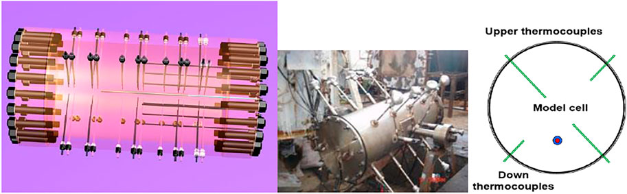
FIGURE 1. Experimental setup for flue gas–assisted steam huff-n-puff in a 3D model.
The parameters used in the experimental model are presented in Table 1. The steam and flue gas injection rate is controlled at 50 cm3/min. The initial feed concentration is composed by 60% of steam, 8% of CO2, and 32% of N2 (assuming the flue gas is composed of 80% N2 and 20% CO2). The components of heavy oil are presented in Table 2. Each huff-n-puff cycle consists of 30 min of injection, soaking for 10 min, and 30 min of production. A total of 11 cycles of huff-n-puff experiments were carried out. The steam huff and puff were carried out in the first six cycles, and then non-condensable gas–assisted steam huff and puff were carried out in the subsequent five cycles, as shown in Figure 2. The steam and gas are injected from the top of the reactor, while the oil producer is set at the bottom of the cell. The detailed experimental setup for flue gas–assisted steam huff-n-puff in a heavy oil 3D model is presented in Figure 2.
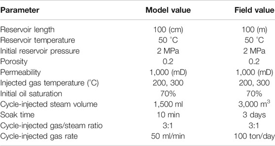
TABLE 1. Parameters used in the experimental model.
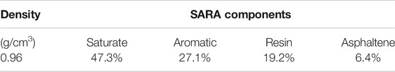
TABLE 2. Components of the heavy oil used in the experiment.
FIGURE 2. Experimental illustration for flue gas–assisted steam huff-n-puff in a heavy oil model.
The heavy oil sample is acquired from the Qigu formation in the Xinjiang oil field. The burial depth of this heavy oil formation is shallow (200–800 m), and the reservoir temperature is low (22–40°C). On the other side, the dead oil viscosity is high (23,670 mPa•s). Thus, it remains a great challenge to produce this kind of reservoir. The oil/steam ratio decreases rapidly after several cycles of steam huff and puff. Thus, the well productivity performance by steam huff-n-puff is poor after some cycles. Flue gas co-injection with steam is considered an enhanced oil recovery process. The reservoir porosity of the acquired core ranges from 0.2 to 0.38. The reservoir permeability ranges from 60 to 5000 mD. The oil density at the surface condition is 0.94–0.98 g/cm3. The flue gas pilot injection was initiated in September 2015. The overall huff-n-puff performance is good for most of the stimulation wells, while steam–flue gas breaks through at some wells. Initially, the flue gas injection was targeted at well pairs. However, there is no clue where the gas breakthrough and the production well are not benefited. Then, the flue gas–steam stimulation plan comprised a group of wells (at least 20 wells of injection–production simultaneously).
Figure 3 shows the heavy oil viscosity variation with different injected gas mixtures. The “indiscernible” viscosity difference for different injected gas and heavy oil mixtures is attributed to the y-coordinates using a base 10 logarithmic scale. The solubility of CO2 in heavy oil is much higher than that of N2 given the same temperature and pressure. The crude viscosity decreases with an increase of gas solubility. The CO2–heavy oil mixture viscosity is the lowest. A major influencing factor that controls the heavy oil viscosity is the system temperature. When the system temperature reaches 120°C, the crude viscosity reduction due to temperature increase is weakened. The solution gas composition in the heavy oil exerts an important role in reducing the crude viscosity, especially in terms of the CO2 content.
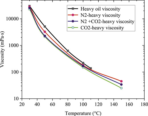
FIGURE 3. Measured oil viscosity under different injected gas mixtures.
Results and Discussion
The Recovery Performance of Flue Gas With Steam Huff-n-Puff in the Laboratory Model
In order to investigate the potential of non-condensable gas injection for improved heavy oil recovery after the steam huff-n-puff process, five cycles of non-condensable gas–assisted steam huff-n-puff were conducted after the primary steam injection process. The experimental process consisted of two stages. The first stage is the cyclic steam injection process. Then, non-condensable gas co-injection with steam is considered the second stage. Steam huff-n-puff was implemented at the first six cycles, and then steam–CO2, steam–N2, and steam–flue gas huff-n-puff processes were continued. The experiments were carried out in the aforementioned laboratory 3D model. The detailed oil production rates of each cycle for steam–N2, steam–flue gas, and steam–CO2 are shown in Table 3, which are consistent with the results presented in Figure 4. The oil recovery factors were obtained by using the production rates of each cycle in Table 3 divided by the initial volume of oil in place. Before implementing the non-condensable gas injection, the incremental oil recovery factor by cyclic steam injection declines significantly with increasing cycles. After the non-condensable gas co-injection with steam, the oil declining rate was reversed. The recovery performance by steam–CO2 huff-n-puff is more favorable than that by steam alone. The steam–CO2 huff-n-puff yields the highest oil recovery. Although after seven cycles of steam huff-n-puff injection, CO2 and nitrogen co-injection with steam still recovers pronounced incremental oil. The retention of water saturation in the reservoir increases with cycles before flue gas injection, which results in a reduction of oil production rates. However, the addition of non-condensable gases provides a driving force for incremental oil recovery.
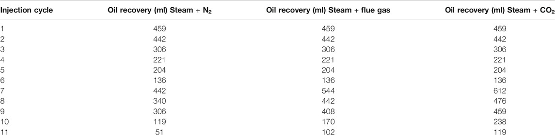
TABLE 3. Each cycle’s recovered oil rate for steam–N2, steam–flue gas, and steam–CO2 injection cases.
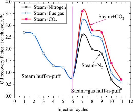
FIGURE 4. Oil recovery factor of each cycle for different injection gases at 240 °C.
The performance of cyclic gas injection operation depends on many factors, such as injection time, injected gas volume, and injected gas composition. One important role of the addition of CO2 and N2 in the steam is to reduce the cumulative heat losses to adjacent formations. The injected CO2 tends to form miscibility with oil, thus decreasing the oil flow resistance. The presence of CO2 and N2 causes the light components in the oil to be carried along in the gas phase. When CO2 condenses in the heavy oil, it reduces the viscosity of the crude at the condensing front. Thus, the net recovery by the CO2–steam huff-n-puff process is considerably higher than that of steam drives. The steam and flue gas tend to occupy the top of the reactor model overriding a large volume of the oil uncontacted due to the density difference between gas and reservoir oil. There is some vertical distance between the steam chamber near the injection well and the perforated well lateral at the bottom of the oil layer, so the steam will not be produced in short time. The steam chamber can continue to expand vertically along the injection well to make full use of the injected steam enthalpy. The front edge of the steam chamber is in a stable state controlled by the vapor–liquid interface, which is similar to the phenomenon in SAGD production.
Table 4 shows the comparison of oil productivity index for different injection schemes. The injected fluid volume was measured at experimental conditions. The injection pressure was controlled at 4.5 MPa, not exceeding 5 MPa. Figure 5 shows the average oil productivity index for different injection gases at different temperatures. It is observed that non-condensable gas co-injection with steam yields the highest oil productivity index. In other words, the addition of CO2 and nitrogen in the steam accelerates the oil production velocity. The productivity index is an important factor to consider when the flue gas co-cycles with steam in field application. A high productivity index means the internal rate of return of the project would be high. It is noted that the oil productivity index increases with an increase of injection temperature. Besides that, the combination of CO2/steam/N2 obtains the higher oil productivity index than steam alone. Recognition of this recovery mechanism has led to addition of non-condensable gas into steam to enhance the production performance.
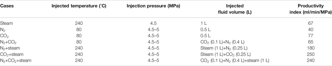
TABLE 4. Comparison of oil productivity index under different injection schemes.
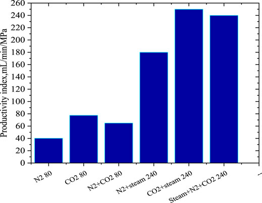
FIGURE 5. Oil productivity index under different injection gases at different temperatures.
The solubility of CO2 and flue gas in the heavy oil phase was compared in the laboratory. When the pressure is constant, the solubility of flue gas in heavy oil decreases with the increase of temperature. The main reason is that the increase of reaction temperature intensifies the molecular motion of non-condensable gas, which reduces its solubility in heavy oil. However, when the temperature remains constant, the increase of the pressure of the mixed system reduces the gas molecular distance and thus increases the gas solubility in heavy oil. The experimental results shown in Figure 6 suggest that the solubility of CO2 is higher than that of flue gas in heavy oil.
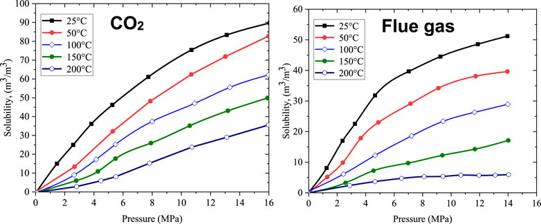
FIGURE 6. Solubility comparison for CO2 and flue gas in heavy oil.
According to the literature survey, some studies reported that they did not observe the effects of temperature on relative permeability and endpoint saturations (Wilson, 1956). On the other side, some reported that the heavy oil relative permeability depends upon the temperature (Edmonson, 1965). The behavior of relative permeability curves of heavy oil with the gas phase at high temperature conditions is difficult to measure. Figure 7 shows the relative permeability curves for steam, CO2, N2, and heavy oil at different temperatures. The unsteady-state method was used to measure the three-phase relative permeability curves of the heavy oil/steam/CO2/N2 system. There are some disagreements on the influence of temperature on the relative permeabilities. The addition of CO2 and N2 can reduce the heavy oil viscosity and increase the relative permeability of oil. The relative permeability curves are affected by the injection of non-condensable gases.
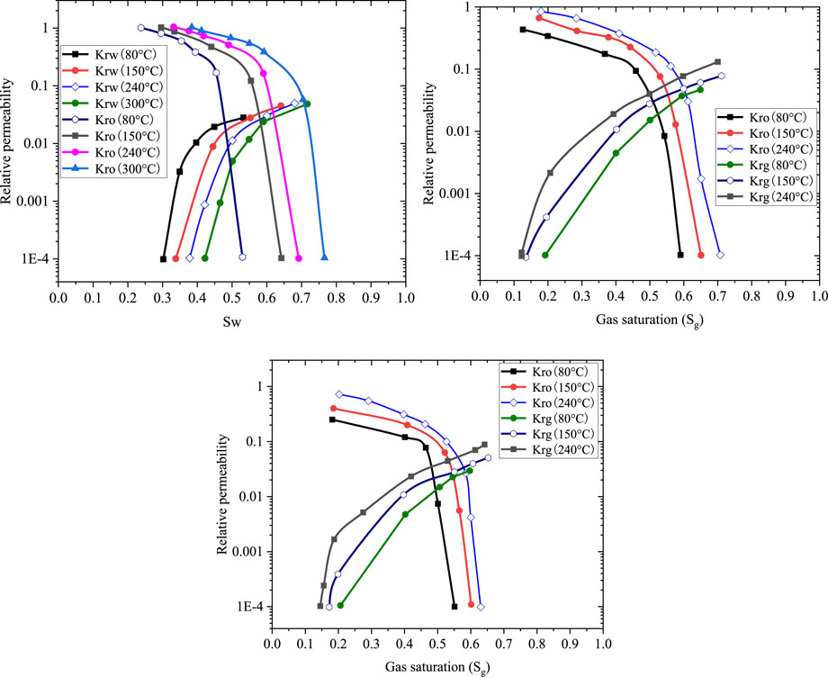
FIGURE 7. Relative permeability curves for steam (the first one), CO2 (the second one), N2 (the third one), and heavy oil at different temperatures.
The residual oil saturation under the high injection temperature is lower than the low injection temperature case. The two-phase flow region at the higher temperature is increased than that at the lower temperature. Given the same injection temperature, the two-phase flow regions for CO2–steam are larger than those of N2–steam because the residual oil saturation for the latter is higher. With an increase of injection temperature, the oil relative permeability increases slightly, while the gas relative permeability improvement is remarkable. The numerical simulation method was used to examine the temperature-dependent relative permeability effect on the cumulative heavy oil production, and simulation results indicated that more oil is recovered by considering the temperature effect (Wan et al., 2019).
Field Practice of Flue Gas With Steam Huff-n-Puff in Heavy Oil Reservoirs
With many cycles of steam injection in the mature heavy oil fields, the oil production rate is declining and approaching tail production. CO2/N2/flue gas co-injection along with steam is considered a way of recovering incremental oil from the fields. Experience gained from gas injection worldwide showed the potential of using CO2 or flue gas for enhanced oil recovery. With the intent of increasing the posttreatment production rate of steam injection, the CO2/flue gas–assisted steam huff-n-puff process was implemented in the field. In the field, flue gas is generated by burning the fuel that is either natural gas or diesel, as shown in Table 5. The flue gas produced by fuel combustion carries significant amount of latent heat with steam into the wellbore.
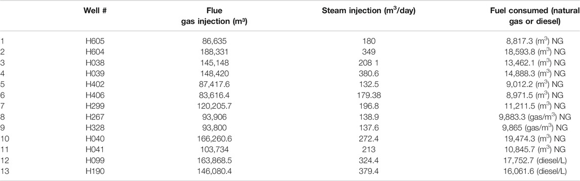
TABLE 5. Injected flue gas volume, steam injection rate, and fuel consumption of each well.
The Hongshan basin is characterized as a set of braided river delta front deposits. Most heavy oil reservoirs in Xinjiang belong to braided fluvial facies and proluvial facies. The main oil-bearing lithology is medium sandstone, which is loosely compacted and sensitive to sand production. The average porosity and permeability are 30.3% and 2,623 mD. The average oil saturation is 78%. The reservoir net pay thickness is 12–23 m with an average of 16 m. The steam drive process has been carried out more than 4 years. Steam breakthrough occurs over the top layer of the reservoir. The underlying formation is bypassed, and the volumetric sweep efficiency is low. Inefficient use of injected fluid pushes the operator to consider for flue gas injection.
The pilot trials of flue gas–steam injection are targeted at shallow formation whose well depth is less than 600 m, and the crude oil viscosity is less than 4,800 MPa·s at 50°C. The average daily oil production rate was 0.42 tons/day with water cut at 95.3% before flue gas injection. Based on the well screening criteria for flue gas injection, 13 wells were selected as the flue gas injection well. The flue gas and surface water injection volume is presented in Table 5. The average flue gas injection volume for each well is 125186 m3. The average injection pressure is constrained at 7 MPa. The average injection period is 8.6 days. The well production profile before flue gas injection is shown in Figure 8A. The average oil production rate is around 0.4 tons/day. Figure 8B shows that, after flue gas injection was implemented, the average daily oil production rate was increased to 1.27 ton/day and water cut was reduced to 80%. The oil production rate has increased more than 100%. The cumulative incremental oil production of the well group was estimated as 5,850 tons. The average incremental oil production rate of each well is 450 tons due to flue gas injection. The incremental oil production is calculated by subtracting the declining rates from the actual cumulative oil production. On the contrary, it is also observed that the water cut declined from 95 to 70%. The use of steam and flue gas injection to stimulation wells has improved the well group production performance.
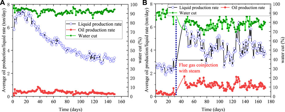
FIGURE 8. Average oil production rate before (A) and after (B) the flue gas injection in the field.
The well H190 in Table 5 is taken as an example to investigate the cyclic steam and flue gas injection process efficiency. Figures 9A,B show the flue gas injection performance for a specific well H190. The oil production rates after the first and second cycles of flue gas injection are demonstrated. The production profile is a good example of flue gas injection, increased oil production by flue gas–steam EOR technique. It is seen that the oil production rate is close to 0 before flue gas injection. A rapid increase in oil production is observed after the flue gas–steam co-injection into the reservoir. In the first cycle, an injection gas comprising of 146080 m3 flue gas was blended into the injection stream. The temperature of the injected gas is 220°C. The injection process continues for 10 days. Then, the well was soaked for 4 days. The peak oil rate is approximately 10 tons/day after the treatment. In addition to that, the water cut of the production liquid dropped from 95 to 50%. It clearly demonstrates the effectiveness of flue gas and steam injection for enhanced oil recovery in the heavy oil field. The incremental oil production due to flue gas injection in the first cycle is estimated as 272 tons. The injected gas volume of the second cycle is 140953 m3 with 250 m3 surface water. However, the peak oil rate in the second cycle declines significantly which is about 4 tons/day. With more cycles of gas injection implemented, successive oil recovery efficiency in the second cycle is decreased as well. Figure 10 shows the measured temperature profile at the first and second cycles of flue gas–steam injection in the wellbore. It is observed that the temperature of the second cycle is higher than that of the first cycle. With more flue gas injected into the reservoir, the unavoidable heat loss is minimized due to the insulating effect of nitrogen and CO2. The non-condensable gas moves at the front of steam chamber that contributes to the resistance to heat flow. The heated formation zone interval is located from 500 to 540 m according to the temperature response in Figure 10. The injected steam and flue gas tend to move to the top of the zone. The successive second cycle of steam and flue gas injection spreads out and expands the heated chamber.
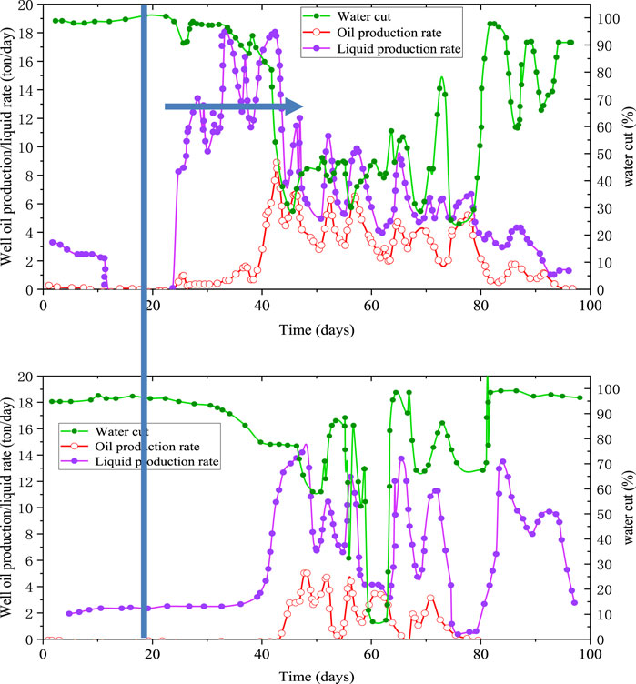
FIGURE 9. Well oil production rate after the first (the first one) and second (the second one) cycles of flue gas injection.
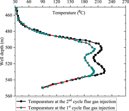
FIGURE 10. Measured temperature profile before and after flue gas–steam injection in the wellbore.
Figure 11 shows the relation of injected gas volume and injection pressure with the peak oil production rates. The relationship between the injected gas volume and the peak oil rate is not clear. It is speculated that fingering of injected gas and steam occurs in the injection process. Most of the injected heat and the flow of fluids tend to break through the high-permeability channels. A similar phenomenon is observed in the field. The plan was to increase the reservoir pressure by flue gas injection for well H604. However, flue gas breaks through early without gaining too much incremental oil recovery. In Figure 12, the oil production response after the flue gas injection is weak. In recognizing the ineffectiveness of flue gas injection, nitrogen foam injection is considered an alternative to enhanced oil recovery. In the field trial, 4.8 tons of foaming agent and 180000 m3 of nitrogen were injected in a duration of 14 days. Surface foam generation was used in case that surfactant and nitrogen enter different channels. The amount of foaming agent required was based on the field experience since similar treatment was conducted in neighboring wells. An increase of reservoir pressure was noticed which means the flow resistance was increased by foam in situ. The average oil production rate for well H604 is 5 tons/day after the nitrogen foam treatment, which is much higher than that of flue gas injection. This increase could result from that the high-permeability communication channels were blocked by nitrogen foam. The water cut was reduced to 50% as well.
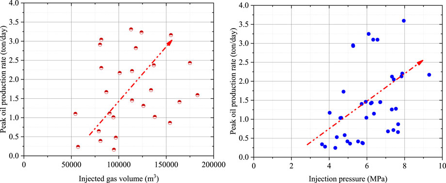
FIGURE 11. Relation between the peak oil production rate, the injected gas volume, and the injection pressure.
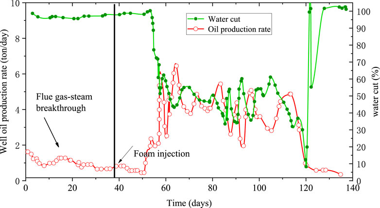
FIGURE 12. Nitrogen foam injection performance for well H604.
Conclusion
In this paper, laboratory studies were conducted to investigate the flue gas, CO2, and N2 effect on steam huff-n-puff recovering heavy oil reservoirs. The flue gas generated by fuel combustion in the field was injected with steam to improve heavy oil recovery. The recovery performance by steam–CO2 huff-n-puff is more favorable than that by steam alone. The steam–CO2 huff-n-puff yields the highest oil recovery. Although after seven cycles of steam huff-n-puff injection, CO2 and nitrogen co-injection with steam recovers pronounced incremental oil. CO2 co-injection with steam yields the highest oil productivity index. Field practice of flue gas with steam huff-n-puff in a heavy oil reservoir also demonstrated the potential for enhanced oil recovery. The peak oil rate in the second cycle declines significantly which is about 4 tons/day. With more cycles of gas injection implemented, successive oil recovery efficiency in the second cycle is decreased as well. Unsuccessful field trial of flue gas injection was also observed due to gas breakthrough in the high-permeability channels. Nitrogen foam injection was considered an alternative to enhanced oil recovery than flue gas injection.
Data Availability Statement
The original contributions presented in the study are included in the article/Supplementary Material, and further inquiries can be directed to the corresponding author.
Author Contributions
ZJ curated the data and wrote the original draft. WT conceptualized the research idea and performed the methodology and experiments.
Conflict of Interest
The authors JQ, JZ, SZ and YW were employed by Xinjiang Oilfield Company.
The remaining author declares that the research was conducted in the absence of any commercial or financial relationships that could be construed as a potential conflict of interest.
Publisher’s Note
All claims expressed in this article are solely those of the authors and do not necessarily represent those of their affiliated organizations, or those of the publisher, the editors, and the reviewers. Any product that may be evaluated in this article, or claim that may be made by its manufacturer, is not guaranteed or endorsed by the publisher.
Abbreviations
EOR, enhanced oil recovery; SAGD, steam-assisted gas drainage; CHT, condensation heat transfer; PNCAs, polymer of N-methylbutenone carboxylates.
References
Bender, S., and Akin, S. (20172017). Flue Gas Injection for EOR and Sequestration: Case Study. J. Pet. Sci. Eng. 157, 1033–1045. doi:10.1016/j.petrol.2017.07.044
Canbolat, S., Serhat, A., and Kovscek, A. R. (2002). “A Study of Steam-Assisted Gravity Drainage Performance in the Presence of Noncondensable Gases,” in SPE/DOE Improved Oil Recovery Symposium (Tulsa, Oklahoma: Society of Petroleum Engineers). SPE 75130. doi:10.2118/75130-ms
Chang, J. (2020). “Flue Gas Waste Heat Utilization for Enhanced Oil Production-Water Hot-Gas Injection for Lloydminster Reservoirs,” in Paper presented at the SPE Canada Heavy Oil Conference, September 28–October 2, 2020. doi:10.2118/199949-ms
Chen, H., Li, H., Li, Z., Li, S., Wang, Y., Wang, J., et al. (2020). Effects of Matrix Permeability and Fracture on Production Characteristics and Residual Oil Distribution during Flue Gas Flooding in Low Permeability/tight Reservoirs. J. Pet. Sci. Eng. 195 (15), 107813. doi:10.1016/j.petrol.2020.107813
Chen, J., Lang, X., Wang, Y., Li, G., Yang, Z., and Fan, S. (2018). Comparative Evaluation of Different Non-condensable Gases on thermal Behaviors, Kinetics, High Pressure Properties, and Product Characteristics of Heavy Oil. Energ. Convers. Manag. 162, 13–25. doi:10.1016/j.enconman.2018.02.029
Dong, M., Huang, S.-S. S., and Hutchence, K. (2006). Methane Pressure-Cycling Process with Horizontal wells for Thin Heavy-Oil Reservoirs. SPE Reserv Eval. Eng. 9, 154–164. doi:10.2118/88500-pa
Dong, X., Liu, H., Hou, J., Zhang, Z., and Chen, Z. (2015). Multi-thermal Fluid Assisted Gravity Drainage Process: a New Improved-Oil-Recovery Technique for Thick Heavy Oil Reservoir. J. Pet. Sci. Eng. 133, 1–11. doi:10.1016/j.petrol.2015.05.001
Edmondson, T. A. (1965). Effect of Temperature on Waterflooding. J. Can. Pet. Technol. 4 (4), 236–242. PETSOC-65-04-09. doi:10.2118/65-04-09
Hoteit, H., and Firoozabadi, A. (2009). Numerical Modeling of Diffusion in Fractured Media for Gas-Injection and -Recycling Schemes. SPE J. 14, 323–337. doi:10.2118/103292-PA
Hoteit, H. (2013). Modeling Diffusion and Gas–Oil Mass Transfer in Fractured Reservoirs. J. Pet. Sci. Eng. 105, 1–17. doi:10.1016/j.petrol.2013.03.00
Irani, M., and Ghannadi, S. (20132013). Understanding the Heat-Transfer Mechanism in the Steam-Assisted Gravity-Drainage (SAGD) Process and Comparing the Conduction and Convection Flux in Bitumen Reservoirs. SPE J. 18, 134–145. doi:10.2118/163079-pa
Ito, Y., Ichikawa, M., and Hirata, T. (1999). “The Effect of Gas Injection on Oil Recovery during SAGD Projects,” in Paper presented at the Annual Technical Meeting, June 13–17, 1999. doi:10.2118/99-19
Kar, T., Ovalles, C., Rogel, E., Vien, J., and Hascakir, B. (2016). The Residual Oil Saturation Determination for Steam Assisted Gravity Drainage (SAGD) and Solvent-SAGD. Fuel 172, 187–195. doi:10.1016/j.fuel.2016.01.029
Kaye, S. E., Ting, V. C., and Fair, J. C. (1982). Development of a System to Utilize Flue Gas from Enhanced Oil Recovery Combustion Projects. J. Pet. Tech. 34 (01), 181–188. doi:10.2118/8360-pa
Lang, L., Li, H., Wang, X., and Liu, N. (20202020). Experimental Study and Field Demonstration of Air-Foam Flooding for Heavy Oil EOR. J. Pet. Sci. Eng. 185, 106659. doi:10.1016/j.petrol.2019.106659
Lawal, K. A. (2014). Economics of Steam-Assisted Gravity Drainage for the Nigerian Bitumen deposit. J. Pet. Sci. Eng. 116, 28–35. doi:10.1016/j.petrol.2014.02.013
Li, H., and Yang, D. (2016). Determination of Individual Diffusion Coefficients of Solvent/CO2 Mixture in Heavy Oil with Pressure-Decay Method. SPE J. 21, 131–143. doi:10.2118/176032-PA
Li, S., Yu, T., Li, Z., and Zhang, K. (2019). Experimental Investigation of Nitrogen-Assisted SAGD in Heavy-Oil Reservoirs: a Two-Dimensional Visual Analysis. Fuel 257, 1–16. doi:10.1016/j.fuel.2019.116013
Li, S., Li, Z., and Sun, X. (2017). Effect of Flue Gas and N -hexane on Heavy Oil Properties in Steam Flooding Process. Fuel 187, 84–93. doi:10.1016/j.fuel.2016.09.050
Li, S., Wang, Q., and Li, Z. (2020). Stability and Flow Properties of Oil-Based Foam Generated by CO2. SPE J. 25 (1), 416–431. doi:10.2118/199339-pa
Liu, H., Cheng, L., Wu, K., Huang, S., and Maini, B. B. (2018). Assessment of Energy Efficiency and Solvent Retention inside Steam Chamber of Steam- and Solvent-Assisted Gravity Drainage Process. Appl. Energ. 226, 287–299. doi:10.1016/j.apenergy.2018.06.017
Liu, P., Shi, L., Liu, P., Li, L., and Hua, D. (2019). Experimental Study of High-Temperature CO2 Foam Flooding after Hot-Water Injection in Developing Heavy Oil Reservoirs. J. Pet. Sci. Eng. 185, 106597. doi:10.1016/j.petrol.2019.106597
Meyer, R. F., Attanasi, E. D., and Freeman, P. A. (2007). Heavy Oil and Natural Bitumen Resources in Geological Basins of the World. Open-File Report. Reston, Virginia: U.S. Geological Survey.
Miller, K. A., Moore, R. G., Ursenbach, M. G., Laureshen, C. J., and Mehta, S. A. (2002). Proposed Airinjection Recovery of Cold-Produced Heavy Oil Reservoirs. J. Canad Petrol. Technol. 41, 40–49. doi:10.2118/02-03-03
Mohammadzadeh, O., Rezaei, N., and Chatzis, I. (2010). Pore-Level Investigation of Heavy Oil and Bitumen Recovery Using Solvent −Aided Steam Assisted Gravity Drainage (SA-SAGD) Process. Energy Fuels 24 (12), 6327–6345. doi:10.1021/ef100621s
Mohsen, K., Ryosuke, O., and Tayfun, B. (20152015). A Semi-analytical Solution to Optimize Single-Component Solvent Coinjection with Steam during SAGD. Fuel 144, 400–414. doi:10.1016/j.fuel.2014.12.030
Mohsenzadeh, A., Escrochi, M., Afraz, M. V., Karimi, G., Al-Wahaibi, Y., and Ayatollahi, S. (2016). Non-hydrocarbon Gas Injection Followed by Steam-Gas Co-injection for Heavy Oil Recovery Enhancement from Fractured Carbonate Reservoirs. J. Pet. Sci. Eng. 144, 121–130. doi:10.1016/j.petrol.2016.03.003
Pang, Z.-x., Wu, Z.-b., and Zhao, M. (20172017). A Novel Method to Calculate Consumption of Non-condensate Gas during Steam Assistant Gravity Drainage in Heavy Oil Reservoirs. Energy 130, 76–85. doi:10.1016/j.energy.2017.04.078
Pang, Z., Lyu, X., Zhang, F., Wu, T., Gao, Z., Geng, Z., et al. (2018). The Macroscopic and Microscopic Analysis on the Performance of Steam Foams during thermal Recovery in Heavy Oil Reservoirs. Fuel 233, 166–176. doi:10.1016/j.fuel.2018.06.048
Pei, S., Cui, G., Wang, Y., Zhang, L., Wang, Q., Zhang, P., et al. (2020). Air Assisted In Situ Upgrading via Underground Heating for Ultra Heavy Oil: Experimental and Numerical Simulation Study. Fuel 279 (6), 118452. doi:10.1016/j.fuel.2020.118452
Peng, D.-Y., and Robinson, D. B. (1976). A New Two-Constant Equation of State. Ind. Eng. Chem. Fund. 15, 59–64. doi:10.1021/i160057a011
Srivastava, R. K., Huang, S., and Dong, M. (1999). Comparative Effectiveness of CO2 Produced Gas, and Flue Gas for Enhanced Heavy-Oil Recovery. SPE Reservoir Eval. Eng. 2 (3), 238–247. doi:10.2118/56857-pa
Sun, H., Wang, Z., Sun, Y., Wu, G., Sun, B., and Sha, Y. (2020). Laboratory Evaluation of an Efficient Low Interfacial Tension Foaming Agent for Enhanced Oil Recovery in High Temperature Flue-Gas Foam Flooding. J. Pet. Sci. Eng. 195, 107580. doi:10.1016/j.petrol.2020.107580
Sun, Q., Li, Z., Li, S., Jiang, L., Wang, J., Wang, P., et al. (2014). Utilization of Surfactant-Stabilized Foam for Enhanced Oil Recovery by Adding Nanoparticles. Energy Fuels 28, 2384–2394. doi:10.1021/ef402453b
Wan, T., Wang, X. J., Jing, Z., and Gao, Y. (2019). Gas Injection Assisted Steam Huff-N-Puff Process for Oil Recovery from Deep Heavy Oil Reservoirs with Low-Permeability. J. Pet. Sci. Eng. 185, 106613. doi:10.1016/j.petrol.2019.106613
Wilson, J. W. (1956). Determination of Relative Permeability under Simulated Reservoir Conditions. Aiche J. 2 (1), 94–100. doi:10.1002/aic.690020120
Yadali Jamaloei, B., Dong, M., and Mahinpey, N. (2021). Experimental and Numerical Study of Strategies for Improvement of Cyclic Solvent Injection in Thin Heavy-Oil Reservoirs. SPE Reservoir Eval. Eng. 24 (01), 127–158. doi:10.2118/203835-pa
Zhang, Y. P., Sayegh, S. G., Huang, S., and Dong, M. (2006). Laboratory Investigation of Enhanced Light-Oil Recovery by CO2/flue Gas Huff-N-Puff Process. J. Can. Pet. Tech. 45 (02), 24–32. doi:10.2118/06-02-01
Zhao, D. W., Wang, J., and Gates, I. D. (2013). Optimized Solvent-Aided Steam-Flooding Strategy for Recovery of Thin Heavy Oil Reservoirs. Fuel 112 (112), 50–59. doi:10.1016/j.fuel.2013.05.025
Keywords: flue gas, CO2, heavy oil, recovery mechanism, EOR
Citation: Qin J, Zhang J, Zhu S, Wang Y and Wan T (2021) Multi-Component Thermal Fluid Injection Performance in Recovery of Heavy Oil Reservoirs. Front. Energy Res. 9:803540. doi: 10.3389/fenrg.2021.803540
Received: 28 October 2021; Accepted: 30 November 2021;
Published: 21 December 2021.
Edited by:
Zhenkun Hou, Guangdong University of Technology, ChinaReviewed by:
Hussein Hoteit, King Abdullah University of Science and Technology, Saudi ArabiaJiaqi Wang, Harbin Engineering University, China
Copyright © 2021 Qin, Zhang, Zhu, Wang and Wan. This is an open-access article distributed under the terms of the Creative Commons Attribution License (CC BY). The use, distribution or reproduction in other forums is permitted, provided the original author(s) and the copyright owner(s) are credited and that the original publication in this journal is cited, in accordance with accepted academic practice. No use, distribution or reproduction is permitted which does not comply with these terms.
*Correspondence: Jing Zhang, emhhbmdqaW5feGpAcGV0cm9jaGluYS5jb20uY24=