 Xiaoliang Hao1
 Fan Ma
- 1National Key Laboratory of Science and Technology on Vessel Integrated Power System, Naval University of Engineering, Wuhan, China
- 2College of Electrical Engineering, Naval University of Engineering, Wuhan, China
As more and more distributed energy resources accessing in a micro-grid, the electromagnetic transient simulation of the whole system becomes extremely complicated due to the increase of multiphase converters. The traditional real-time simulation models of multiphase converters are low in efficiency for their large number of electronic switches and power system nodes. To solve this problem, an efficient real-time simulation modeling method based on high-order approximation is proposed. Starting with the symmetry of structure, the twelve-phase converter and induction motor are equivalent to a three-phase converter and induction motor and thus reducing the order of the model. The switching function model of the three-phase converter is derived, and the mathematical expressions of switching functions are calculated by high-order approximation expansion of the Fourier series; then, the dc input current of the three-phase converter is formulated theoretically. Counteracting the harmonics by means of phase-shifting, the high-order approximation model of the twelve-phase converter is constructed. Finally, the real-time simulation platform and experimental platform of the twelve-phase frequency converter and induction motor are built; the simulation results verify the high efficiency and accuracy of the proposed real-time simulation model compared with traditional models of the multiphase frequency converter.
Introduction
With the access to various types of energy, the penetration of power electronic converters in the micro-grid is increasing. Large capacity and multiple sets of multiphase frequency converters have high power density, high reliability, and strong comprehensive properties, making them the main device of high-power speed-regulating equipment (Ma, 2015; Li et al., 2021a; Li et al., 2021b). As the number of phases increases, the number of switches contained in multiphase power electronic devices increases; these switches are turned on and off frequently, leading to the increase in the amount of electromagnetic transient real-time simulation calculation and the decrease in the efficiency (Gnanarathns et al., 2010; Saad et al., 2014). It brings difficulties to the accurate quantitative calculation of the system and the design of circuit parameters and control structure (Tu and Xu, 2011; Xu et al., 2013). So, it is urgent to study an efficient real-time simulation modeling method of multiphase converters to improve the efficiency and accuracy.
The scholars at home and abroad have conducted a lot of research on the modeling of multiphase converters, which can be divided into the following categories: detailed models (Chen et al., 2020; Pan et al., 2020; Ye et al., 2021), switching function models (Dimitrov et al., 2020; Jiang et al., 2021), average-value models (Hengsi Qin and Kimball, 2012; Peralta et al., 2012; Zhang et al., 2017; Feng et al., 2021), and other models (Andres, 2018; HuangXin et al., 2018). In the studies by (Chen et al., 2020; Pan et al., 2020; Ye et al., 2021), the authors present the application scope of the detailed models, switching function models, and average-value models of the controllable inverter. The detailed model is high in accuracy but low in efficiency, especially the converters with hundreds of switches. The efficiency of the switching function model is limited by the number of power system nodes. The average-value model has the highest efficiency for the reason of ignoring the characteristics of high-frequency harmonics. The switching function model of MMC and the DC-DC converter is established in the studies by (Dimitrov et al., 2020; Jiang et al., 2021), which significantly improves the calculation efficiency. It can be used to guide the design of circuit topology and parameters, and it is suitable for occasions where only external characteristics of the equipment are concerned. The average-value model of the 401-level MMC-HVDC system is established in the study by (Peralta et al., 2012). The efficiency of the average-value model is 370 times more than that of the detailed model, but it has a certain loss in accuracy. In the studies by (Hengsi Qin and Kimball, 2012; Zhang et al., 2017), the continuous and discrete full-order average-models considering power loss are built based on the traditional average-value model of the DC-DC converter. In the study by (Feng et al., 2021), the authors point out that the common defect of the average-value model is that the system is averaged, which greatly reduces the accuracy in the steady state and cannot simulate the fault state. In addition, some authors have proposed many new modeling methods. They attempt to improve the efficiency by using the Thevenin or Norton equivalent circuit (Andres, 2018; HuangXin et al., 2018), but these models are limited by the stability of numerical calculation; their simulation steps cannot be increased to more than 50 μs, and the computational accuracy is relatively low. In the studies by (Shu et al., 2016; Shu et al., 2019), the ac/dc system is divided into the dc network and ac network; the shifter frequency phasor model is used to accelerate the dc network, and a hybrid multi-domain transmission line model is developed to realize the multi-domain collaborative simulation. These methods either seek to improve the efficiency or accuracy, and they are rarely promoted together. Therefore, this study intends to study an efficient real-time simulation model of the multiphase converter, which can improve the calculation efficiency without loss of accuracy.
Aiming at the low efficiency of the traditional real-time simulation model of the multiphase converter, an efficient modeling method is proposed in this study. First, the multiple sets of the converter and induction motor are equivalent to a single set of the converter and induction motor from the symmetry of the structure, and the control parameters after equivalent are calculated. Second, the switching function model of the three-level H-bridge is established, which is the minimum unit of the multiphase converter, and the sinusoidal pulse width modulation (SPWM) is generated by high-order approximation transformation of Fourier series, then analytically calculating the mathematical expression of the dc input current of the multiphase converter. Third, counteracting the harmonics by phase-shifting on the dc side, the efficient real-time simulation model is constructed. Finally, the real-time simulation platform and experimental platform of the twelve-phase frequency converter and induction motor are built; comparing with real-time simulation results and experimental results of the detailed model and average-value model, it is verified that the proposed real-time simulation model can greatly improve the efficiency on the premise of ensuring the high accuracy.
The main contributions of this work are highlighted here:
• Constructing the detailed model, average-value model, and switching function model of the multiphase frequency converter and simulating the dynamic process of the converter with the induction motor load.
• Proposing a real-time simulation modeling method of the multiphase converter based on high-order approximation transformation of Fourier series. Compared with the traditional models, the proposed model can greatly improve the real-time simulation efficiency and maintain the accuracy consistent with the actual device together.
• The proposed modeling method can be extended to the field where the small step real-time simulation is necessary in the case of higher accuracy requirements.
The remaining parts of this study are organized as follows: in Section 2, the circuit topology and control structure of the twelve-phase converter are constructed. In Section 3, the real-time simulation modeling method of the multiphase converter based on high-order approximation is described in detail. Finally, the comparison results of the proposed model and the traditional detailed model are presented in Section 4.
Circuit Topology and Control Structure of the Detailed Model of the Twelve-Phase Frequency Converter
Figure 1 shows the main circuit topology of the twelve-phase converter; it is powered by the dc power supply with a midpoint, and 12 three-level H-bridges are connected in parallel. Each H-bridge is composed of three-level inverter half-bridges clamped by two diodes with left and right symmetry. The converter is modulated by the SPWM strategy to obtain the IGBT control signals, whose modulation wave is inverse and carrier is in-phase (Hu et al., 2019). As shown in Figure 2, Us1(t) and Us2(t) are the inverse modulation waves, Uc1(t) and Uc2(t) are the in-phase triangle carriers, and the modulation wave is compared with the carrier to generate the switching signal Ga1.
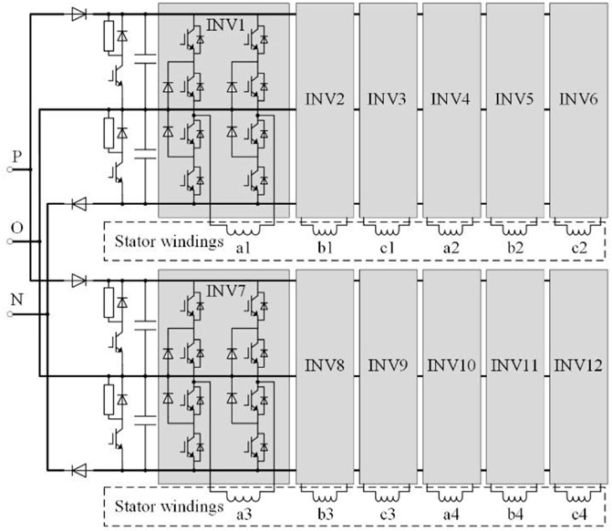
FIGURE 1. Main circuit topology of the twelve-phase frequency converter.
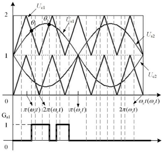
FIGURE 2. Cascade PWM modulation.
The rotor flux-oriented control mode is adopted in the frequency conversion speed control structure (Ai et al., 2019). The ac current vector is decomposed into the excitation current component and torque component whose directions are perpendicular to each other. The excitation current component is oriented on the d-axis of the rotor flux, and the torque component is oriented on the q-axis to realize the separate control of each other.
The traditional detailed model of the converter is low in efficiency for the reasons as follows: first, the main circuit of the twelve-phase converter in Figure 1 contains 252 power electronic switches. These centrally distributed switches are frequently turned on and off, which makes it difficult to realize the small-step real-time simulation of the multiphase converter (Liu et al., 2019). Second, the number of power system nodes in traditional detailed model is large so as to the order of node matrix of the whole system is very high especially in the system with multiple sets of multiphase converters, so it is difficult to solve quickly.
Real-Time Simulation Modeling Method of the Multiphase Frequency Converter Based on High-Order Approximation
Equivalent Simplified Model of the Twelve-Phase Converter and Induction Motor
The twelve-phase converter is composed of four sets of three-phase converter which shift phase 15 in turn. It is equivalent to a three-phase converter, and the power is deduced to 1/4 of its original. In the converter’s control parameters, the stator voltage reference value remains unchanged, the stator current reference value becomes 1/4 of the original, and the impedance parameters can be calculated by the induction motor equations.
Accordingly, the twelve-phase induction motor is equivalent to the three-phase induction motor, the stator voltage remains unchanged, and the stator current meets the following equations.
where id1, iq1, id2, iq2, id3, iq3, id4, and iq4 are the stator current on the dq axis in the four sets of windings of the twelve-phase induction motor.
Then, the mathematical equations of the three-phase induction motor are as follows.
Stator voltage equation and flux linkage equation:
Rotor voltage equation and flux linkage equation:
Output torque and equation of motion:
where ω is the rational electric angular velocity of the dq coordinate system, ωr is the mechanical angular velocity of the rotor, Te is the electromagnetic torque, TL is the load torque, np is the pole numbers, J is the rational inertia, ud1, uq1, u01, id1, iq1, i01, idr, iqr, ψd1, ψq1, ψ01, ψdr, and ψqr are voltages, currents and flux linkages of the stator, and rotor in the first set of winding of the original twelve-phase induction motor. The stator voltage Udqs=(ud1 uq1 u01)T, stator flux linkage ψdqs=(ψd1 ψq1 ψ01)T, stator current Idqs=(id1/4 iq1/4 i01/4)T, rotor flux linkage ψdqr=(ψdr ψqr)T, rotor current Idqr=(idr iqr)T, Rr = diag ([Rr Rr]), Rs = diag ([4Rp 4Rp 4Rp]), L1 = 6Ls1+4Lsm1_1+4Lsm1_2+2Lsm1_3, L2 = 4Ldqm1_1+6Ldqm1_2+2Ldqm1_3.
After the simplification, the original twelve-phase frequency converter and induction motor can be simplified into a three-phase converter and induction motor. The speed-adjusted structure through frequency conversion is simplified from four sets to one set, which improves the calculation efficiency.
Switching Function Model of the Three-Phase Frequency Converter
The switching function model has a high calculation efficiency and accuracy and can reflect the input and output harmonic characteristics of all the traditional real-time simulation models. The three-phase converter is connected in parallel with three 120° phase-shifting three-level H-bridges. According to the cascading waves and the conduction law of IGBTs in Figure 2, the switching function of the three-level H-bridge can be written as follows:
And, G1+G3 = 1, G2+G4 = 1, G5+G7 = 1, and G6+G8 = 1. Here, G1∼G8 are the switching function of the switches in the three-level H-bridge, Upo is the voltage from the positive pole on the dc side to the clamping midpoint, Uno is the voltage from the negative pole on the dc side to the clamping midpoint, Uab is the output voltage on the ac side, and Iin is the input current on the dc side, and I is the stator current on the ac side.
Based on the voltage and current relationship in 8, 9, the three-phase H-bridge can be replaced by the controlled sources circuit shown in Figure 3, and the switching function model of the three-phase converter can be formed by shifting phase 120° and 240°, respectively.
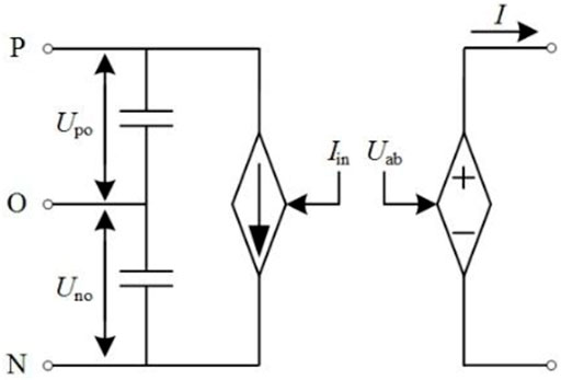
FIGURE 3. Equivalent switching function circuit topology of the three-level H-bridge.
Up to now, the efficiency has been improved by the switching function model of the converter. However, in order to further improve the efficiency and calculate the external characteristics of the converter more accurately, it is necessary to solve each harmonic value of the input voltage and current in turn and carry out harmonic counteraction according to the phase-shift angle. Therefore, the high-order approximation model is formulated.
High-Order Approximation Model of the Three-Phase Frequency Converter
According to the PWM modulation waveforms shown in Figure 2, for the switch signal GA1, there are multiple intersections θ1 and θ2 between the modulation wave Us1(t) and the triangular carrier Uc1(t) in (0, π) within one period of the modulation wave, while in (π, 2π), Us1(t) is always less than Uc1(t); then, the switching signal GA1 is determined by the intersections θ1 and θ2 of the modulation wave and the carrier wave. Similarly, the same modulation law exists for the other switches.
Within (0, π) of the modulation wave, the switching signal GA1 is an alternating pulse sequence of 0–1, and it can be Fourier expanded as follows:
where ωc is the carrier frequency, θ1 and θ2 are determined by the intersections of the modulation wave and the carrier wave, G(t) is the switching function of the electronic switch, n is the harmonic order, an is the coefficient of the n-fold frequency-cosine, and bn is the coefficient of the n-fold frequency-sine. Therefore, the triangular carrier can be written as (the parameters of the control structure are standardized, so the amplitude of the carrier wave is set as 1) follows:
where, i = 0, 1, 2, 3,…
It is assumed that the modulation wave is:
where ma is the modulation ratio, ωs is the modulation wave frequency, and φ1 is the initial phase angle of the modulation wave.
So θ1 and θ2 can be calculated by simultaneous 11 and 12:
By substituting 13 into 10, the Fourier expansion expression of GA1 in (0, π) of the modulation wave can be obtained. In (π, 2π), the switching signal GA1 is constant to 0.
Similarly, the switching signal GA2 is expanded in the same way as GA1, and the mathematical expressions of GA1 and GA2 can be obtained as follows:
where
The harmonic terms Ga1t(t) and Ga2t(t) can be expanded to different orders according to the requirements of the calculation accuracy and efficiency.
Based on the current equation in 9, the dc input current of phase A in the first set of the equivalent three-level H-bridge is
where Iain is the dc input current of phase A in the three-phase converter, Ia is the ac stator current of phase A in the three-phase converter, and Ia can be written as follows according to the dynamic equations of the induction motor:
where φ2 is the initial phase angle of the stator current.
The mathematical expression of the dc input current of phase A can be solved by combining 15 and 16.
In order to calculate the harmonic content on the dc input side of the converter more accurately, the three-phase converter is re-extended to the twelve-phase converter. The dc input current of the three-level H-bridge of phase A is shifted to 120°, 240°, 15°, 15° + 120°, 15° + 240°, 30°, 30° + 120°, 30° + 240°, 45°, 45° + 120°, and 45° + 240°, respectively. Thus, the input current of the remaining 11 three-level H-bridges can be obtained, then carrying out harmonic counteraction between different phases, and the dc input current of the twelve-phase converter is obtained. The mathematical model of the converter is connected to the main circuit in the form of controlled sources, and the ac load is equivalent to a controlled current source to the dc side; the input voltage can be generated automatically without a separate solution.
This method not only ensures the calculation accuracy and can reflect the input harmonic characteristics but also provides a way to adjust the calculation efficiency of the model; the users can choose the complexity of the model according to their computational needs.
Real-Time Simulation and Experimental Verification
In order to verify the accuracy and efficiency of the real-time simulation model proposed in this study, the detailed model, average-value model, and high-order approximation model of the twelve-phase converter with the twelve-phase induction motor load are constructed on the Rt-lab real-time simulation platform, and also, we carried out the physical experiment on actual equipment as a comparison.
Introduction of the Real-Time Simulation Platform
The real-time simulation platform is composed of a set of OP5700 RT-LAB real-time simulator from Opal-RT in Canada and a laptop host computer. The target computer of the OP5700 simulator is used for real-time simulation calculation, including two Intel 8-cores/3.2 GHz processors and 8 GB memory. It is connected with the host computer through Ethernet. The host computer is used to establish the model and monitor the simulation data; its CPU is a 2.8 GHz ASUS Intel Cores i7-7,700 processor, and 64-bit windows operating system with 8 GB memory is installed. The platform structure is shown in Figure 4.
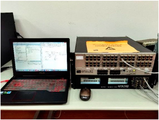
FIGURE 4. Diagram of the real-time simulation platform.
Comparison and Verification of the Accuracy Between the High-Order Approximation Model and Other Models
In order to verify the accuracy of the established high-order approximation model of the twelve-phase converter, the input and output characteristics of different models that we constructed are compared. Among them, the input characteristics (voltage and current) are analyzed from two aspects: the dc component and the total harmonic distortion (THD), and the following results are obtained.
The working condition is set as follows: a twelve-phase converter and a twelve-phase induction motor are put into operation, and the speed of the induction motor maintains 180 r/min.
It can be seen from the Figures 5, 6 that the results of the high-order approximation model are in good agreement with experimental results in terms of the input and output characteristics. There is some error between the proposed method and the experimental results; it is because the foundation of our method is the switching function modeling method, which cannot simulate the freewheeling process of the switch elements, and the error is within the acceptable range. Moreover, there are many other electrical devices in field tests, which have certain influence on the harmonic calculation of the converter. Compared with the average-value model, the proposed model has the same content of the dc component, while the high-order approximation model can reflect the harmonic characteristics, and it is more accurate than the average-value model.
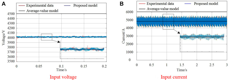
FIGURE 5. DC input voltage and current of the twelve-phase converter.
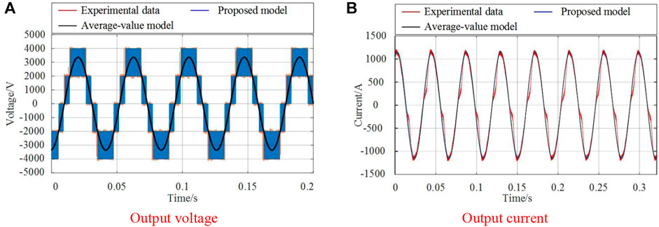
FIGURE 6. AC output voltage (left) and current (right) of the twelve-phase converter.
Besides, the steady-state dc input voltage and current of the converter are compared and analyzed from the dc component and THD in detail. Here, the THD of the input voltage and current are defined as follows:
where Vi and Ii are the ith harmonic component, and Vdc and Idc are the dc components.
The comparison results are as Tables 1, 2.
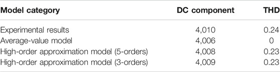
TABLE 1. The DC component and THD of the input voltage in the twelve-phase converter.
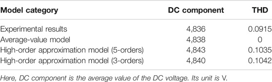
TABLE 2. The DC component and THD of the input current in the twelve-phase converter.
By comparing the above high-order approximation model with the experimental results and the average-value model, it can be seen that the three models are consistent in the amount of the dc component, and the proposed high-order approximation model can reflect harmonic characteristics as the experimental results, while the average-value model cannot. So the proposed high-order approximation model can realize high-precision real-time simulation, and its accuracy is basically the same with the actual device.
Comparison and Verification of the Efficiency Between the High-Order Approximation Model and Other Models
To verify the high efficiency of the established high-order approximation model of the twelve-phase converter, the real-time simulation performances of different models we constructed are compared on the RT-LAB real-time simulation platform, as shown in Figure 4. The comparison is made in terms of simulation resources (CPU cores) consumed, and the simulation step can be achieved. Among them, when carrying out the real-time simulation of the detailed model, for the reason that the switches contained in a single subnet in the RT-LAB real-time simulation platform should not be too much (Uriate and Dufour, 2013); the detailed model is partitioned and decoupled, and each three-level H-bridge in the twelve-phase converter is separated from each other for real-time processing.
1) There are two sets of propulsion systems (with two sets of converters and induction motors) in a typical integrated power system, so the cores consumed by two sets of propulsion systems by different modeling methods when the simulation step is 30 μs are compared. The comparison results are as in Table 3.
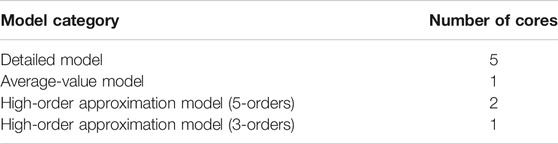
TABLE 3. The number of cores consumed by different kinds of models.
As can be seen from the above real-time simulation results, when calculating two sets of propulsion systems under the same simulation step, the number of cores consumed by the average-value model and the high-order approximation 3-order models are the same, which reduces the simulation resources consumed by 80% compared with the detailed model.
2) Also, the minimum simulation step can be achieved of different models when two sets of propulsion systems are calculated in one core are compared; the results are as in Table 4.
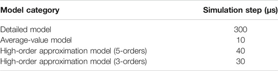
TABLE 4. The simulation step can be achieved by different kinds of models.
From the results in Table 4, the calculation step of the average-value model is the smallest, followed by the high-order approximation model (3-orders); the proposed model reduces the simulation step by 90% compared with the detailed model. Usually, the smaller the step is, the higher the calculation accuracy is for fast transient characteristics (Farque et al., 2015). The steps of the average-value model and the high-order approximation model are all less than 50 μs, which is usually the most proper step in electromagnetic transient simulation of the power system (Yu et al., 2015), while the step of the detailed model is too large to be acceptable for practical application.
After the comparison in the above two aspects of real-time simulation, the established high-order approximation model of the twelve-phase converter can greatly improve the efficiency and reduce the simulation step compared with the traditional detailed model, and the loss in accuracy is small. The high-order approximation 3-order model has the same accuracy as the 5-order model, but the 3-order model has higher computational efficiency. Therefore, from the perspective of saving simulation resources, the high-order approximation 3-order model is selected as our final model.
In order to demonstrate the superiority of the proposed model more directly, the comparison results are shown in Figure 7. From which it can be seen that the proposed high-order approximation modeling method of the multiphase converter greatly improves the real-time simulation efficiency; it reduces the number of electronic switches from 252 to 6, and the simulation step and cores consumed are also greatly reduced compared with the detailed model. The efficiency of the average-value model is higher than that of the proposed model; it is for the reason that the average-value model ignores the harmonic characteristics, and it is not accurate enough, while the accuracy of the proposed model is consistent with the experimental results of the actual device. So the most outstanding innovation of the proposed model is that it not only greatly improves the efficiency but also maintains the precision of the detailed device model. With the increase of the converters in number, the advantages of the high-order approximation model will become more and more significant in the micro-grid (Li et al., 2022).
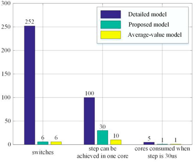
FIGURE 7. Real-time simulation performance comparison results of different models.
Conclusion
A high-order approximation modeling method of the multiphase frequency converter based on the expansion of Fourier series is proposed in this study. The control structure is simplified by equating the twelve-phase converter and twelve-phase induction motor to a three-phase converter and a three-phase induction motor. Then, the mathematical expression of the dc input current of the converter is derived by a high-order approximate expansion of Fourier series, and the input current of the three-phase converter is re-extended to the twelve-phase converter by means of phase shifting and harmonic counteraction. This method solves the problem of low efficiency of the traditional multiphase converter models. Finally, the real-time simulation results of the high-order approximation model are compared with that of the average-value model, the detailed model, and physical experimental results; the results show that:
1) In terms of calculation accuracy, the modeling method proposed in this study greatly improves the simulation accuracy compared with the average-value model. It can achieve the accuracy of the detailed device model.
2) In terms of calculation efficiency, the modeling method proposed in this study reduces the number of electronic switches from 252 to 6, which is beneficial to the improvement of the simulation performance. Compared with the detailed model, the proposed model reduces the simulation step by 90%, and the simulation resources consumed by 80%; it greatly improves the simulation efficiency.
3) The modeling method proposed in this study can be extended to any multiple sets of multiphase electronic device whose switching function exists. It provides a way to adjust the model complexity, and the users can adjust the complexity of the model according to the requirements of the simulation efficiency and accuracy.
In the future, we will construct a hardware-in-the-loop real-time simulation platform to study the energy management system of the whole micro-grid. It is necessary to provide accurate and real-time calculated data for the energy management system. Besides, we will develop a set of power system analysis software, including system state estimation software, bad data monitoring software, the static security analysis software, and self-healing control software. It can provide a test platform for the operation state analysis, system control, and protection strategy design of the micro-grid.
Data Availability Statement
The original contributions presented in the study are included in the article/Supplementary Materials, further inquiries can be directed to the corresponding author.
Author Contributions
XH contributed to the methodology, software, formal analysis, resources, and writing. LF was responsible for methodology, project administration, and funding acquisition. FM helped with the conceptualization, methodology, validation, and writing review editing. LH provided materials and guidance. XZ helped with writing review editing and experiment.
Funding
This research work was supported in part by the National Natural Science Foundation of China Grant (51877211) and the National Key Basic Research Program 973 Project of China under Grant (613294).
Conflict of Interest
The authors declare that the research was conducted in the absence of any commercial or financial relationships that could be construed as a potential conflict of interest.
Publisher’s Note
All claims expressed in this article are solely those of the authors and do not necessarily represent those of their affiliated organizations, or those of the publisher, the editors, and the reviewers. Any product that may be evaluated in this article, or claim that may be made by its manufacturer, is not guaranteed or endorsed by the publisher.
References
Ai, S., Sun, C., and Zhang, C. (2019). Vector Control Algorithm for Fifteen-phase Induction Motor. Adv. Technol. Electr. Eng. Energ. 35 (16), 26–30. doi:10.3969/j.issn.1003-3076.2013.04.006
Andres, L. E. (2018). Short-term Frequency Regulation and Inertia Emulation Using an MMC-Based MTDC System. IEEE Trans. Power Syst. 33 (3), 2854–2863. doi:10.1109/TPWRS.2017.2757258
Chen, W., Wu, M., and Zhang, J. (2020). Review of Electromagnetic Transient Modeling of Modular Multilevel Converter. Power Syst. Technol. 44 (12), 4755–4765.
Dimitrov, V., Hinov, N., and Vacheva, G. (2020). Switch Function Modelling of Bidirectional DC-DC Converter. Bulgaria: International Scientific Conference ElectronicsSozopol.
Farque, M. O., Strasser, T., and Lauss, G. (2015). Real-time Simulation Technologies for Power Systems Design, Testing, and Analysis. IEEE Power Energ. Technol. Syst. J. 2 (2), 63–73.
Feng, M., Gao, C., Ding, J., Ding, H., Xu, J., and Zhao, C. (2021). Hierarchical Modeling Scheme for High-Speed Electromagnetic Transient Simulations of Power Electronic Transformers. IEEE Trans. Power Electron. 36 (9), 9994–10004. doi:10.1109/tpel.2021.3061421
Gnanarathns, U. N., Gole, A. M., and Jayasinghe, R. P. (2010). Efficient Modeling of Modular Multilevel HVDC Converters (MMC) on Electromagnetic Transient Simulation Programs. IEEE Trans. Power Deliv. 26 (1), 316–324. doi:10.1109/TPWRD.2010.2060737
Hengsi Qin, H., and Kimball, J. W. (2012). Generalized Average Modeling of Dual Active Bridge DC-DC Converter. IEEE Trans. Power Electron. 27 (4), 2078–2084. doi:10.1109/tpel.2011.2165734
Hu, L., Xiao, F., and Lou, X. (2019). Research on Output Voltage Abnormal Voltage Pulses of Three-Level H-Bridge Inverter Based on Cascaded Carrier Modulation. Proc. CSEE 39 (1), 266–276. doi:10.13334/j.0258-8013.pcsee.172323
HuangXin, L. H., Xin, H., Yang, H., Wang, Z., and Xie, H. (2018). Interconnecting Very Weak AC Systems by Multiterminal VSC-HVDC Links with a Unified Virtual Synchronous Control. IEEE J. Emerg. Sel. Top. Power Electron. 6 (3), 1041–1053. doi:10.1109/jestpe.2018.2825391
Jiang, Z., Chen, Y., Zhang, B., Qiu, D., and Xie, F. (2021). Multiscale Modeling and Analysis of Boost Converter Based on Device Mechanism Model and Continuous Switching Function. IEEE J. Emerg. Sel. Top. Power Electron. 9 (4), 4225–4235. doi:10.1109/jestpe.2020.3041275
Li, Y., Li, K., and Yang, Z. (2022). Stochastic Optimal Scheduling of Demand Response-Enabled Microgrids with Renewable Generations: an Analytical-Heuristic Approach. J. Clean. Prod., 330. doi:10.1016/j.jclepro.2021.129840
Li, Y., Wang, C. L., and Li, G. P. (2021b). Optimal Scheduling of Integrated Demand Response-Enabled Integrated Energy Systems with Uncertain Renewable Generations: a Stackelberg Game Approach. Energ. Convers. Manage., 235. doi:10.1016/j.enconman.2021.113996
Li, Y., Han, M., Yang, Z., and Li, G. (2021a). Coordinating Flexible Demand Response and Renewable Uncertainties for Scheduling of Community Integrated Energy Systems with an Electric Vehicle Charging Station: a Bi-level Approach. IEEE Trans. Sustain. Energ. 12 (4), 2321–2331. doi:10.1109/tste.2021.3090463
Liu, Y., Zhang, B., and Xie, F. (2019). Multiscale Modeling and Analysis of DC/DC Converter Based on Marco- and Micro-scale Description. IEEE Trans. Energ. Convers. 35 (1), 356–365. doi:10.1109/TEC.2019.2939171
Ma, W. M. (2015). Electromechanical Power Conversion Technologies in Vessel Integrated Power Systems. J. Electr. Eng. 10 (4), 3–10.
Pan, E., Yang, H., and Song, Z. (2020). An Efficient Modeling of Modular Multi-Level Converter Based on DC Grids by Using Larger Time-Steps. Proc. CSEE 40 (19), 6142–6249. doi:10.13334/j.0258-0813.pcsee.191307
Peralta, J., Saad, H., and Denetiere, S. (2012). Detailed and Averaged Models for a 401-level MMC-HVDC System. IEEE Trans. Power Deliv. 27 (30), 1501–1508. doi:10.1109/tpwrd.2012.2188911
Saad, H., Dennetiere, S., Mahseredjian, J., Delarue, P., Guillaud, X., Peralta, J., et al. (2014). Modular Multilevel Converter Models for Electromagnetic Transients. IEEE Trans. Power Deliv. 29 (3), 1481–1489. doi:10.1109/tpwrd.2013.2285633
Shu, D., Yan, L., and Zhang, C. (2016). Converter Averaged Model Based on Amplitude Distribution Function and its Applications. Automation Electric Power Syst. 40 (15), 73–78. doi:10.7500/AEPS20150930002
Shu, D., Xie, X., Yan, Z., Dinavahi, V., and Strunz, K. (2019). A Multi-Domain Co-simulation Method for Comprehensive Shifted-Frequency Phasor DC-grid Models and EMT AC-Grid Models. IEEE Trans. Power Electron. 34 (11), 10557–10574. doi:10.1109/tpel.2019.2899651
Tu, Q., and Xu, Z. (2011). Impact of Sampling Frequency on Harmonic Distortion for Modular Multilevel Converter. IEEE Trans. Power Deliv. 26 (1), 298–306. doi:10.1109/tpwrd.2010.2078837
Uriate, F. M., and Dufour, C. (2013). “Multicore Methods to Accelerate Ship Power System Simulations,” in IEEE Electric Ship Technologies Symposium (Arlington, VI: ESTS), 139–146.
Xu, J. Z., Zhao, C. Y., and Liu, W. J. (2013). Accelerated Model of Ultra-large Scale MMC in Electromagnetic Transient Simulations. Proc. CSEE 33 (10), 114–120.
Ye, H., Gao, F., Pei, W., and Kong, L. (2021). Wave Function and Multiscale Modeling of MMC-HVdc System for Wide-Frequency Transient Simulation. IEEE J. Emerg. Sel. Top. Power Electron. 9 (5), 5906–5917. doi:10.1109/jestpe.2021.3051647
Yu, L., Xu, A., and Guo, X. (2015). Real-time Transient Simulation and Analysis of Active Distribution Network Based on RTDS. Proc. CSU-EPSA 27 (4), 18–24. doi:10.3969/j.issn.1003-8930.2015.04.004
Keywords: multiphase converter, real-time simulation, switching function, high-order approximation, efficiency and accuracy of the model
Citation: Hao X, Fu L, Ma F, Hu L and Zhang X (2022) Real-Time Simulation Modeling Method of Multiphase Converters Based on High-Order Approximation in Micro-grid. Front. Energy Res. 9:829382. doi: 10.3389/fenrg.2021.829382
Received: 05 December 2021; Accepted: 30 December 2021;
Published: 20 January 2022.
Edited by:
Chen Chen, Xi’an Jiaotong University, ChinaReviewed by:
Chen Liang, Nanjing University of Information Science and Technology, ChinaJun Yin, North China University of Water Resources and Electric Power, China
Copyright © 2022 Hao, Fu, Ma, Hu and Zhang. This is an open-access article distributed under the terms of the Creative Commons Attribution License (CC BY). The use, distribution or reproduction in other forums is permitted, provided the original author(s) and the copyright owner(s) are credited and that the original publication in this journal is cited, in accordance with accepted academic practice. No use, distribution or reproduction is permitted which does not comply with these terms.
*Correspondence: Fan Ma, bWFmYW4wODAzQDE2My5jb20=