 Jingxuan Li
 Yixun Xue
 Yuan Du1
- 1College of Electrical Engineering, Taiyuan University of Technology, Taiyuan, China
- 2Department of Electrical Engineering, Tsinghua University, Beijing, China
- 3Shanxi Energy Internet Research Institute, Taiyuan, China
- 4China Power Integrated Smart Energy Co., Ltd., Beijing, China
District heating systems have been widely used in large and medium-sized cities. Typical district heating systems consist of the primary heating system (PHS) and the secondary heating system (SHS) operating in isolation. However, the isolated dispatch of the PHS and the SHS has poor adjustability and large losses, resulting in unnecessary operation costs. To address these issues, a coordinated economic dispatching model (CEDM) for the primary and secondary heating systems considering the boiler’s supplemental heating is proposed in this study, which characterized the physical properties of the PHS and the SHS in detail. Considering that the PHS and the SHS are controlled separately without central operators in practice, it is difficult to dispatch them in a centralized method. Thus, the master-slave splitting algorithm is innovatively introduced to solve the CEDM in a decentralized way. Finally, a P6S12 system is utilized to analyze and verify the effectiveness and optimality of the proposed algorithm.
Introduction
District heating is widely utilized at the urban scale because of its energy-saving and environmental protection. According to statistics, district heating has been under development in Russia for over 100 years. It contributes 86% of the total national heat demand, more than half of which comes from combined heat and power (CHP). In Denmark, district heating is now responsible for heating almost 98%. In China, the district heating supply rate in large and medium-sized northern cities has reached over 60%.
Many scholars have conducted research on the optimal design of district heating systems (DHS) in recent years. Lund and Mohammadi (2016) proposed ways to improve DH piping by increasing insulation standards, thereby reducing heat and temperature losses from the network. Noussan et al. (2017) proposed the types and determination of heating load to guarantee the safety and stability of the heating supply. Gu et al. (2018) used the BP algorithm methods for dynamic prediction of the heating load. Kaliatka et al. (2014) increased the design stage of the valve layout based on the traditional design process. Dalla Rosa et al. (2011) introduced suggestions for the optimal design of district heating systems for low-energy applications. It also puts forward some methods for reducing heat loss. On the basis of these research studies, a three-dimensional numerical model of heat loss is proposed to explore the difficulties of modeling energy losses in heating systems (Danielewicz, et al., 2016).
In addition, the prerequisite for ensuring the quality and safety of heat supply is the stability of the operation, so the operation optimization and control strategy of the heating systems need to be studied. Wu et al. (2021) proposed a method which uses quality regulation for heating systems. A method that varies the flow rate by means of a pump with a frequency converter according to the outdoor temperature is proposed (Kuosa, et al., 2013). Sun et al. (2021) established a strategy based on online prediction and indoor temperature feedback, which is beneficial to improve the regulation level of heating. Wang et al. (2016) used a novel matrix model of district heating networks to improve the accuracy of calibration temperature predictions. Lu et al. (2021) developed an integrated model in TRNSYS to obtain operation optimization by considering the energy consumption and time-of-use price. Sun et al. (2022) researched the control strategy integrated to improve prediction accuracy and realized energy-saving operation.
However, the aforementioned studies considered that the PHS and SHS of the DHS operate in isolation, which would likely bring some problems: 1) the CHP has a flat output and a small adjustment range because the contract signed between the PHS and SHS specifies a stable temperature of the PHS. 2) The higher temperatures required to ensure the quality of heating will result in more heat loss. 3) Extensive use of the boiler output rather than cooperating with CHP will cause high costs. Thus, a novel dispatch mode in which the PHS and SHS are coordinated to fully utilize the heating sources should be studied in depth.
Considering that the PHS and SHS are controlled separately by different companies in practice, the centralized solution for the coordinated economic dispatch model (CEDM) of the primary and secondary heating systems may encounter some troubles. 1) Detailed topologies or operation states could not be exchanged between the PHS and SHS. 2) It is difficult to control both of them in the centralized method. To cope with these issues, the master-slave splitting algorithm is applied to realize privacy protection and information interaction between the PHS and SHS. The optimality and effectiveness of master-slave splitting are demonstrated.
The main contributions of our work are as follows:
1) We develop the CEDM of the primary and secondary heating systems considering the boiler’s supplemental heating in this study. The differences between the PHS and SHS are analyzed, which are also modeled. By coordinating the PHS and SHS, the problems including poor adjustability, high losses in the heating systems, and high operating costs due to the isolated operation can be solved.
2) The master-slave splitting algorithm is innovatively introduced in the CEDM of the primary and secondary heating systems. The original problem will be broken down into PHS sub-problems and SHS sub-problems, which will be solved by iteration of the two sub-problems Thus, it will solve the problems of difficult information interaction and privacy protection.
The remainder of this study is organized as follows: in Section 2, the formulation of the problem is presented. In Section 3, a decentralized solution based on a master-slave splitting algorithm is developed. In Section 4, the cases are studied to verify the effectiveness and optimality of the algorithm. In Section 5, the conclusions are summarized.
2 Problem formulation
This section focuses on modeling the primary and secondary heating systems. First, it introduces the structure of the heating systems and analyzes the differences between the operation of the PHS and SHS. Based on this, the primary and secondary heating systems are modeled and the operation formulation is established finally.
2.1 The differences between the primary and secondary heating systems
Figure 1 shows a typical urban DHS consisting of a PHS and SHS. In the PHS, heat is generated by CHP units and delivered to the heat exchange station. Then, heat is distributed to consumers through the SHS. In the SHS, the boiler also generates heat for supplementary heat through the heat exchange station. These two parts of the heat are transported to the heat load through the secondary pipe network (Lin et al., 2019).
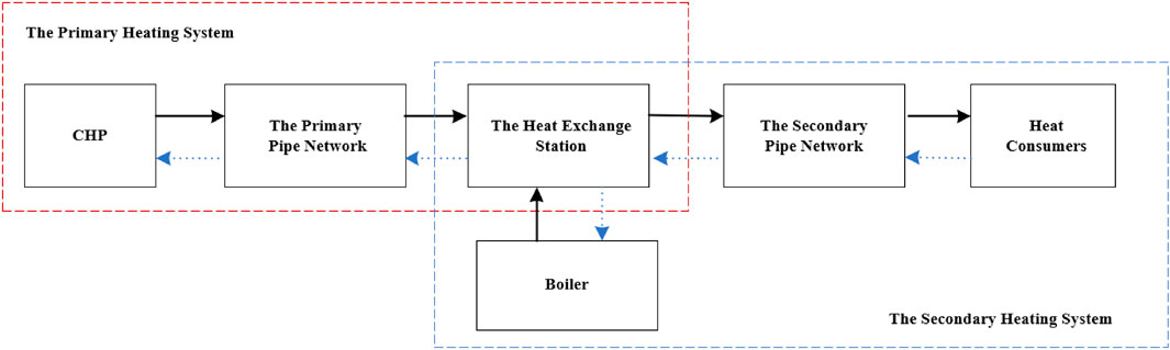
FIGURE 1. Structure of urban district heating systems.
As shown in Table 1, the heating systems are regulated differently and the accommodation mode of the PHS is quality regulation. It is suitable for situations where the mass flow rate is considered to be constant in the model. So the hydraulic constraints for the PHS are satisfied. Both of the constraints of the SHS need to be considered. The mode of the SHS is quantity regulation because of the varied mass flow rate (Deng et al., 2021).
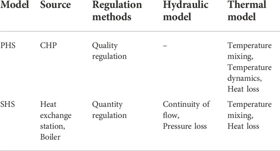
TABLE 1. Difference between the primary and secondary heating systems.
2.2 Modeling the primary and secondary heating systems
The pipe network is the most important of heating systems. A typical structure of the pipe is shown in Figure 2 (Li et al., 2015).
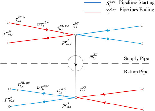
FIGURE 2. Typical structure of pipes.
In Figure 2, the pipes are divided into supply pipes and return pipes.
where
The aforementioned constraints are applicable to the PHS and SHS. The nodal method is utilized to formulate the thermal model in the PHS.
2.2.1 The primary heating network
However, these constraints are inapplicable in the CEDM because of numerous non-linear terms. It is difficult to solve non-linear problems in optimization problems. Thus, we simplify the model by temperature dynamics and heat loss. Temperature dynamics can be expressed as the pipe outlet temperature estimated using the pipe inlet temperature from past periods (Xue et al., 2020), as shown in Figure 3.
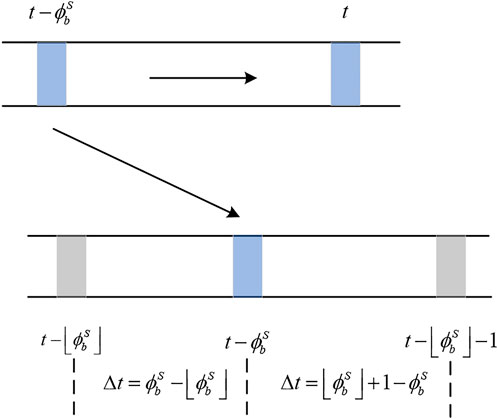
FIGURE 3. Estimation of our temperature.
where
2.2.2 The secondary heating network
Unlike the PHS, the mass flow rate of the SHS is not constant. Thus, it is necessary to take the hydraulic constraints into account. The continuity of flow pressure loss is expressed as the sum of the inflow and outflow flows at the node 0.
Considering the friction between the fluid and the pipes, there are fluid pressure drops in the SHS where
The frequency of the pipeline decreases if the flow rate increases. It causes pipeline instability. So the pipeline flow rate must be limited.
Because of short piping distances in secondary heating systems, the delay is not taken into account. As the temperature of the pipes differs from that of the outside world, there is a loss of temperature.
2.3 Operation model
The objective function of the CEDM is formulated as
where
The constraints are as follows: the power and heat output of the CHP (10), the output limit of the CHP (11), the heat generated by the CHP (12), the operating costs of the CHP (13), the heat transmission (14)-(15), the heat output of the boiler (16), the output limit of the boiler (17), the operating costs of the boiler (18), power consumption of the pump (19), the limit of power consumption (20), the operating costs of power consumption (21), the energy of the load (22), and the limit of temperature (23).
where
3 Solving strategy
The PHS and SHS are controlled separately without central operators in practice which will face many problems. To solve the problems posed, the decentralized solving strategy of the CEDM is given in this section as shown in Figure 4.
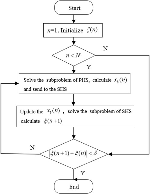
FIGURE 4. Diagram of the iteration procedure.
3.1 Model analysis
To facilitate the subsequent discussion, the CEDM is rewritten in a vector form (Xue et al., 2021).
where the variable for the PHS is denoted as
3.2 Formulation of the decentralized sub-problem
Based on the master-slave split method, the original problem can be decomposed into the PHS economic dispatch sub-problem and the SHS economic dispatch sub-problem. For the PHS economic dispatch sub-problem, it can be expressed as the following equation:
By solving the SHS economic dispatch sub-problem, the boundary information (BI)
3.3 Iteration procedure
The two sub-problems decomposed from the original problem can be solved by iteration. First, the PHS solves its own scheduling problem. It passes the boundary information to the SHS after completing the solution. The SHS schedules internally based on this information then provide the boundary information injection to the PHS.
Figure 4 shows the specific iteration procedure. The iterations will begin with the PHS sub-problem after initialization including set n = 1, the maximum number of iterations to N, the accuracy of convergence to δ, and initialize the boundary information
4 Case studies
4.1 Case setting
Figure 5 shows an F6S12 system which is composed of the primary and secondary heating systems with the 6-node PHS and the 12-node SHS. The time resolution is 1 h.

FIGURE 5. Diagram of the F6S12 system.
To verify the superiority of the CEDM, an isolated economic dispatch model (IEDM) is used for comparison. In the IEDM, the PHS and SHS can only exchange BI via the heat exchange station. In the CEDM, all decision variables can be changed.
The case was tested using MATLAB 2018b on a 2.80 GHz i7-1165G7 CPU with 16 G and solved using the MatlabYalmip toolbox and the open source packages Ipopt solver and Gurobi solver.
4.2 Comparison of coordinated and isolated modes
CHP units have poor regulation in the IEDM. The PHS and SHS have signed contracts that determine the temperature of the PHS. This temperature is largely stable, so the heating output of the CHP is flatter. A small adjustment range will lose the advantage of CHP. As shown in Figure 6, it is up to the boiler to respond to changes in load.
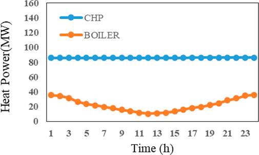
FIGURE 6. Heat source output in IEDM.
On the contrary, the PHS and SHS work collaboratively with each other in the CEDM as shown in Figure 7. The CHP units have an increased range of regulation. The CHP units can provide peak loads, which can be balanced daytime heat load when less heat is required. The boiler’s supplemental heating plays a role in the early hours of the morning or at night when the heat load is high.
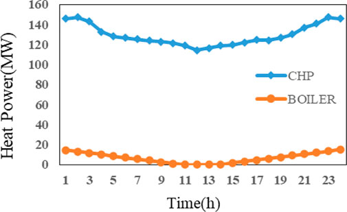
FIGURE 7. Heat source output in CEDM.
In addition, the temperature of the PHS is generally set higher to ensure the quality of the supply in the IEDM, while the quality could be adjusted to the demand of the load in the CEDM. Therefore, the temperature could be brought down as shown in Figure 8. The temperature of the return water network has also been reduced, so it is not shown in Figure 8.
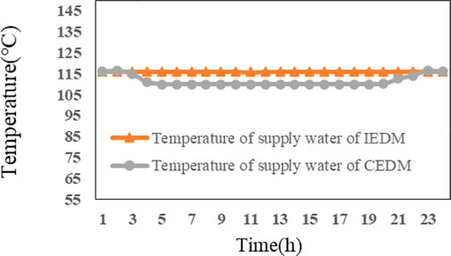
FIGURE 8. Supply water in two modes.
Moreover, the PHS has long lines during transmission as shown in Figure 9, which can cause significant heat loss in IEDM The CEDM, on the other hand, can reduce the heat loss to the environment during transmission by reducing the temperature.
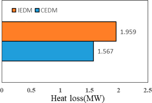
FIGURE 9. Heat loss in two modes.
As shown in Table 2, the coordinated economic dispatch in the CEDM is more economical than in the IEDM. The CEDM could take the advantages of CHP units to be fully exploited, using CHP units to meet the vast majority of the heat demand. It can also take advantage of the boiler’s supplemental heating to reduce the output of the boiler and costs.
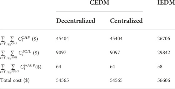
TABLE 2. Cost of two modes and algorithms.
Moreover, centralized and decentralized algorithms have the same results, verifying the validity of the proposed algorithm which refers to the master-slave split method. Moreover, the decentralized algorithm converges with the same Karush–Kuhn–Tucker conditions compared to the centralized algorithm. So the solution obtained satisfies optimality.
5 Conclusion
In this study, the coordinated economic dispatch model (CEDM) of the primary and secondary heating systems considering the boiler’s supplemental heating is established to solve the problems in DHS operations, such as the small regulation range of CHP units, high losses in the heating systems, and high costs. The reliability of the model has been verified using examples. Also, based on the actual physical characteristics, the distributed coordinate economic dispatch based on the master-slave split method is applied in the primary and secondary heating systems, which solves the problems of difficult information interaction and privacy protection. It proved the optimality of the master-slave splitting method in non-convex scenarios.
Data availability statement
The original contributions presented in the study are included in the article/Supplementary Material; further inquiries can be directed to the corresponding authors.
Author contributions
We develop the CEDM of the primary and secondary heating systems considering the boiler’s supplemental heating in this study. The differences between the PHS and SHS are analyzed, which are also modeled. By coordinating the PHS and SHS, problems including poor adjustability, high losses in the heating systems, and high operating costs due to the isolated operation can be solved. The master-slave splitting algorithm is innovatively introduced in the CEDM of the primary and secondary heating systems. The original problem will be broken down into PHS sub-problems and SHS sub-problems, which will be solved by iteration of the two sub-problems. Thus, it will solve the problems of difficult information interaction and privacy protection.
Funding
This work was supported by the National Natural Science Foundation of China (NSFC), grant number U2066206.
Conflict of interest
YS was employed by China Power Integrated Smart Energy Co., Ltd.
The remaining authors declare that the research was conducted in the absence of any commercial or financial relationships that could be construed as a potential conflict of interest.
Publisher’s note
All claims expressed in this article are solely those of the authors and do not necessarily represent those of their affiliated organizations, or those of the publisher, the editors, and the reviewers. Any product that may be evaluated in this article, or claim that may be made by its manufacturer, is not guaranteed or endorsed by the publisher.
References
Dalla Rosa, A., Li, H., and Svendsen, S. (2011). Method for optimal design of pipes for low-energy district heating, with focus on heat losses. Energy 36 (5), 2407–2418. doi:10.1016/j.energy.2011.01.024
Danielewicz, J., Śniechowska, B., Sayegh, M. A., Fidorów, N., and Jouhara, H. (2016). Three-dimensional numerical model of heat losses from district heating network pre-insulated pipes buried in the ground. Energy 108, 172–184. doi:10.1016/j.energy.2015.07.012
Deng, L., Sun, H., Li, B., Sun, Y., Yang, T., and Zhang, X. (2021). Optimal operation of integrated heat and electricity systems: A tightening McCormick approach. Engineering 7 (8), 1076–1086. doi:10.1016/J.ENG.2021.06.006
Gu, J., Wang, J., Qi, C., Min, C., and Sundén, B. (2018). Medium-term heat load prediction for an existing residential building based on A wireless on-off control system. Energy 152, 709–718. doi:10.1016/j.energy.2018.03.179
Kaliatka, A., Vaišnoras, M., and Valinčius, M. (2014). Modelling of valve induced water hammer phenomena in A district heating system. Comput. Fluids 94, 30–36. doi:10.1016/j.compfluid.2014.01.035
Kuosa, M., Kontu, K., Mäkilä, T., Lampinen, M., and Lahdelma, R. (2013). Static study of traditional and ring networks and the use of mass flow control in district heating applications. Appl. Therm. Eng. 54 (2), 450–459. doi:10.1016/j.applthermaleng.2013.02.018
Li, Z., Wu, W., Shahidehpour, M., Wang, J., and Zhang, B. (2015). Combined heat and power dispatch considering pipeline energy storage of district heating network. IEEE Trans. Sustain. Energy 7, 12–22. doi:10.1109/TSTE.2015.2467383
Lin, C., Wu, W., Wang, B., Shahidehpour, M., and Zhang, B. (2019). Joint commitment of generation units and heat exchange stations for combined heat and power systems. IEEE Trans. Sustain. Energy 11 (3), 1118–1127. doi:10.1109/TSTE.2019.2917603
Lu, M., Zhang, C., Zhang, D., Wang, R., Zhou, Z., Zhan, C., et al. (2021). Operational optimization of district heating system based on an integrated model in TRNSYS. Energy Build. 230, 110538. doi:10.1016/j.enbuild.2020.110538
Lund, R., and Mohammadi, S. (2016). Choice of insulation standard for pipe networks in 4th generation district heating systems. Appl. Therm. Eng. 98, 256–264. doi:10.1016/j.applthermaleng.2015.12.015
Noussan, M., Jarre, M., and Poggio, A. (2017). Real operation data analysis on district heating load patterns. Energy 129, 70–78. doi:10.1016/j.energy.2017.04.079
Sun, C., Chen, J., Cao, S., Gao, X., Xia, G., Qi, C., et al. (2021). A dynamic control strategy of district heating substations based on online prediction and indoor temperature feedback. Energy 235, 121228. doi:10.1016/j.energy.2021.121228
Sun, C., Liu, Y., Gao, X., Wang, J., Yang, L., and Qi, C. (2022). Research on control strategy integrated with characteristics of user's energy-saving behavior of district heating system. Energy 245, 123214. doi:10.1016/j.energy.2022.123214
Wang, J., Zhou, Z., and Zhao, J. (2016). A method for the steady-state thermal simulation of district heating systems and model parameters calibration. Energy Convers. Manag. 120, 294–305. doi:10.1016/j.enconman.2016.04.074
Wu, X., Zhang, Q., Chen, C., Li, Z., Zhu, X., Chen, Y., et al. (2021). Optimal dispatching of integrated electricity and heating system with multiple functional areas considering heat network flow regulation. Energies 14 (17), 5525. doi:10.3390/en14175525
Xue, Y., Li, Z., Lin, C., Guo, Q., and Sun, H. (2020). Coordinated dispatch of integrated electric and district heating systems using heterogeneous decomposition. IEEE Trans. Sustain. Energy 11, 1495–1507. doi:10.1109/TSTE.2019.2929183
Keywords: district heating systems, the primary and secondary heating systems, supplemental heating, coordinated economic dispatching model, master-slave splitting
Citation: Li J, Xue Y, Du Y, Pan Z, Zhang J, Shao Y and Sun H (2023) Coordinated economic dispatch of the primary and secondary heating systems considering the boiler’s supplemental heating. Front. Energy Res. 10:1005784. doi: 10.3389/fenrg.2022.1005784
Received: 28 July 2022; Accepted: 31 August 2022;
Published: 20 January 2023.
Edited by:
Dongliang Xiao, South China University of Technology, ChinaReviewed by:
Han Wang, Shanghai Jiao Tong University, ChinaWei Gan, Cardiff University, United Kingdom
Copyright © 2023 Li, Xue, Du, Pan, Zhang, Shao and Sun. This is an open-access article distributed under the terms of the Creative Commons Attribution License (CC BY). The use, distribution or reproduction in other forums is permitted, provided the original author(s) and the copyright owner(s) are credited and that the original publication in this journal is cited, in accordance with accepted academic practice. No use, distribution or reproduction is permitted which does not comply with these terms.
*Correspondence: Yixun Xue, eHVleWl4dW5AdHl1dC5lZHUuY24=; Hongbin Sun, c2hiQHRzaW5naHVhLmVkdS5jbg==