 Fali Huo1
 Jie Xu
- 1School of Naval Architecture and Ocean Engineering, Jiangsu University of Science and Technology, Zhenjiang, China
- 2School of Mathematics Science, Harbin Engineering University, Harbin, China
At present, researches on floating offshore wind turbine are mainly focused on deep water areas beyond 50 m, and less research has been conducted for shallow water. Considering that the floating fan still has many application values in 30 m–50 m area, it is necessary to study the floating offshore wind turbine in shallow water area. With the shallow design water depth and the effect of topography, the environmental condition is complex. Therefore, it is relatively difficult to design the mooring system. In this paper, a multi-point mooring system is proposed which based on PivotBuoy, a floating offshore wind turbine designed by X1-Wind Company. The characteristics of motion responses of the floating offshore wind turbine and mooring force under different mooring cable schemes are studied by physical model experiment. Through these results, it can be found that when the mooring system adopts the hybrid mooring cable scheme (anchor chain + polymer cable + anchor chain), the pitch and heave motion responses of the floating offshore wind turbine will increase by about 30% maximally, the mooring cable tension will decrease by about 27%. This paper also studies the influence of water depth and mooring cable pretension on the mooring system under the hybrid mooring cable scheme, and the characteristics of mooring system in 22.5 m shallow water. These results can provide certain theoretical guidance for the design of mooring system of floating offshore wind turbine in shallow water.
Introduction
In response to global climate issues and the development of new energy technologies, the offshore wind power is receiving more and more attentions. In these offshore wind power technologies, floating offshore wind turbine which can be placed in the deep sea with abundant wind energy and adapted to different terrains, are gradually becoming the mainstream of offshore wind power. There are three main types of floating offshore wind turbine: Spar, semi-submersible and TLP. Spar-type floating offshore wind turbine has simple structure, light weight and little heave motion response. Owing to the deep installation area Spar-type floating offshore wind turbine is relatively difficult to operate. Semi-submersible floating offshore wind turbine installation water depth is flexible, it can be assembled in the port before towing to the operating area. But, semi-submersible floating offshore wind turbine has the disadvantages of heave structure and complicated design. TLP floating offshore wind turbine has light weight, great stability, flexible installation water depth. However, it is mooring force is large and the installation cost is high. With the development of floating offshore wind turbines, a lot of researches are conducted by many researchers.
The paper focuses on the Yellow Sea and East China Sea, where there are many developed economies in the vicinity that require large amounts of power supply. Considered that the average water depth in these areas is 38 m–46 m, and the cost of fixed offshore wind turbines is large, so floating offshore wind turbines are used and their mooring characteristics in shallow water are investigated.
When the wave propagates from deep water to shallow water, the wave form will change dramatically by topography and other factors, such as shorter wavelength, larger wave amplitude, steeper wave and wave breaking. Wang (Wang, 2017) compared the influences of sinking volume and pitch motion response of ships in deep and shallow waters by introducing the Froude number. Concluded that the shallow water effect has more drastic effects on the sinking volume and pitch motion response of ships. Zhang (Zhang, 2019) gave the definition of shallow water effect, pointed out the conditions of the occurrence of shallow water effect, and proposed a set of empirical equations for rapid assessment of shallow water effect, thus achieving rapid prediction of shallow water effect.
Traditional mooring system usually adopts full anchor chain scheme, this scheme with the disadvantages of higher self-weight and higher cost. Changing of the mooring cable scheme can ensure the safety of the structures movement and control the cost. Paul et al. (McEvoy et al., 2021) proposed an innovative mooring scheme(fiber + spring) for large mooring lengths in shallow waters. They tested characteristics of the mooring system at 30 m, 40 m and 50 m water depths, respectively, considered different FSM (Fiber Spring Mooring) configurations, different mooring cable lengths, and fiber-to-spring ratios. Zhang et al. (Zhang et al., 2020) designed seven mooring concepts under 50 m water depth, including tension mooring cable and catenary mooring cable, different material combinations of mooring cables. Compared the characteristics of mooring cables, motion response amplitude operators, and cost utilization factors for all mooring schemes. Brommundt et al. (Brommundt et al., 2012) developed a numerical tool to optimize the catenary mooring cable of floating offshore wind turbines in 45 m to 330 m water depths, respectively, and investigated the optimal cable length, angle and horizontal distance between the anchor point and the mooring port. Benassai et al. (Benassai et al., 2014) compared the performance of motion control of catenary mooring system and tension mooring systems for Dutch floating offshore wind turbine at water depths between 50 m and 200 m. Lin et al. (Lin et al., 2021) conducted a study on the overall performance of floating offshore wind turbine, and found that the heave motion response of the floating offshore wind turbine and mooring cable force are more sensitive to water depth variation. Xu et al. (Xu et al., 2020) proposed a novel mooring system with side-mooring cables for a semi-submersible platform. The effects of the side-mooring cables on the floating platform motion response, mooring tensions and mooring fatigue damage are evaluated by comparing the results without side-mooring cables installed. Magnus et al. (Bach-Gansmo et al., 2020). investigated the effect of angle and pretension on the motion response of TetraSpar for tensioned mooring cables. The results show that the angle and pretension mainly affect the natural period of surge and yaw, and that larger pitch amplitudes compared to the catenary system.
Considering the limitations of numerical simulation, which may lead to distortion of the calculation results, researchers are more likely to obtain metrics for the parameters of the study object by physical models experiment. Guo et al. (Guo et al., 2016) studied the model experiment methods for offshore floating offshore wind turbines, includes similar criteria, experimental conditions and experimental items, and introduced the basin experiment schemes. Liu et al. (Liu et al., 2015) conducted physical model experiment on the characteristics of the motion response of a 5MW semi-submersible floating offshore wind turbine. Obtained the characteristics of the inherent motion response of the turbine system, the characteristics of amplitude-frequency response, and the law of the surge, heave, and pitch motion responses of the floating offshore wind turbine when affect by constant wind. Yang et al. (Yang et al., 2022) conducted a study on a barge-type floating offshore wind turbine through a physical model experiment, verified that the floating offshore wind turbine can meet the demand in the specified areas. Zhao et al. (Zhao et al., 2018) carried out experimental research on the new multi-column tension leg-type floating turbine. The results established the natural period, damping, motion response amplitude operator and tendon tension of the TLP system under different environmental conditions. Liu et al. (Liu et al., 2021) carried out an experimental study of a pool model of a floating offshore wind turbine at 1:50 scaling. The results show that wind loads have a controlling effect on the overall trend of the structural response, while wave loads mainly control the amplitude of the structural response. Huang et al. (Huang and Yang, 2021) carried out the design and optimisation of mooring cables for a 5MV floating offshore wind turbine and found that the mooring costs were minimal in the 60 m - 80 m depth water. Yang et al. (Yang et al., 2021) used a model with a scaling ratio of 1:65.3 to obtain the six-degree-of-freedom motion response of the floating offshore wind turbine, the stresses on the mooring system and the stresses on the dangerous points.
In this paper, we conduct the physical model experiment based on a new semi-submersible floating offshore wind turbine, and investigate the mooring system characteristics of the floating offshore wind turbine in shallow water with different mooring systems or different water depths. It provides a reference for the arrangement of the floating offshore wind turbine in shallow water.
The parameters of mooring system
Parameters of the floating offshore wind turbine
A new type of floating offshore wind turbine PivotBuoy designed by X1-Wind Company is taken as the research object of this paper. The floating offshore wind turbine has lighter floating body, which significantly reduces steel demand. It can be used as a foundation for 15 MW turbine, thus facilitating the economic and efficient deployment of large offshore wind farms. The conceptual model of the floating offshore wind turbine is shown in Figure 1.
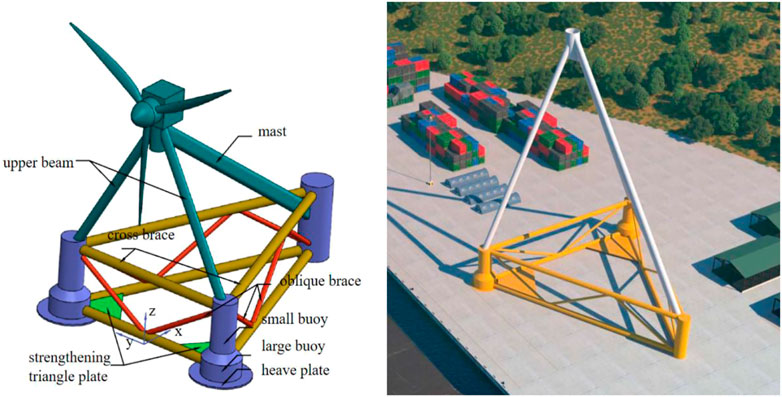
FIGURE 1. Conceptual model of the floating offshore wind turbine.
Design of mooring system
Different from the single-point mooring system adopted by the prototype, the paper designs a multi-point mooring system based on the floating offshore wind turbine. The mooring system is composed of three groups of mooring cables, each group contains two mooring cables with an interval of 10°. To reduce the mooring radius and the tension of the mooring cable, the paper adopts the hybrid mooring cable (anchor chain + polymer cable + anchor chain) as the mooring cable scheme. The layout radius of mooring cable is 300 m, and the total length of the mooring cable is 308 m, of which the top section is 18 m long R4 mooring chain with 95 mm diameter, the midst section is 100 m long polyester cable with 100 mm diameter, the bottom section is 190 m long R4 mooring chain with 95 mm diameter, the pretension force of hybrid mooring cable scheme is 83 kN, and the six mooring cables are the same. In this paper, a set of full anchor chain scheme is set up to compare with the hybrid mooring scheme to study the characteristics of the mooring system, the pretension force of full anchor chain scheme is 370 kN. The preliminary design scheme is shown in Figure 2, the parameters of the hybrid mooring cable scheme and full anchor chain scheme are shown in Table 1 and Table 2, respectively.
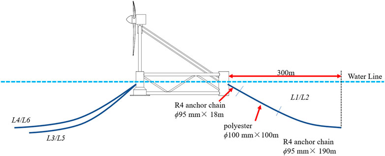
FIGURE 2. Design of mooring system.
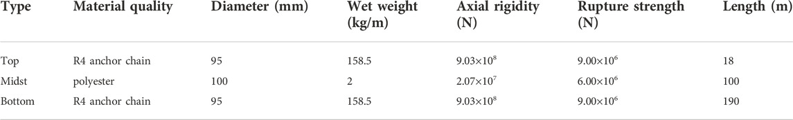
TABLE 1. Practical parameters of hybrid mooring cable scheme.
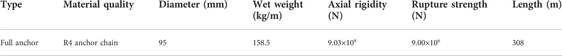
TABLE 2. Practical parameters of full anchor chain scheme.
Design of physical model experiment
Introduction of the experimental basin
The physical model experiment of the new floating offshore wind turbine mooring system was carried out in the wind-wave-current comprehensive basin in Jiangsu University of Science and Technology. The basin is 38 m long and 15 m wide, the maximum effective depth is 1 m. The panoramas of the experimental basin are shown in Figure 3.
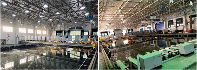
FIGURE 3. Panoramas of wind-wave-current comprehensive basin.
Parameters of the physical model
By referring to the requirements of Wave Model Experiment Procedure, combining with the effective section size and wave-making capacity of experiment basin, and considering the prototype size of the floating offshore wind turbine, and wave design conditions, a model scale of 1:50 is selected in the experiment.
The model is built by tubes with different diameters, which can be divided into 30 mm, 60 mm, 160 mm, and 210 mm. 30 mm tubes are mainly used as reinforcement support, 60 mm tubes are used as the main frame, 160 mm and 210 mm are used as the floating body. The mast is used as support to connect the top wind turbine and the lower column. The model is made by nylon and ABS, the thickness of the model is only 0.5 mm in order not to affect the center of gravity of the floating offshore wind turbine. The physical model is shown in Figure 4. The specific parameters of the floating offshore wind turbine are shown in Table 3.
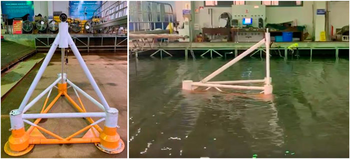
FIGURE 4. Diagram of physical model.

TABLE 3. Parameters of the floating offshore wind turbine.
Figure 5 is the diagram of connection scheme. The beam and the small buoy use the steel structure to connect with each other by interpolation method, and the steel structure is fixed on the small buoy. The model buoys are hollow, where can set the solid pressure load to balance the floating offshore wind turbine.
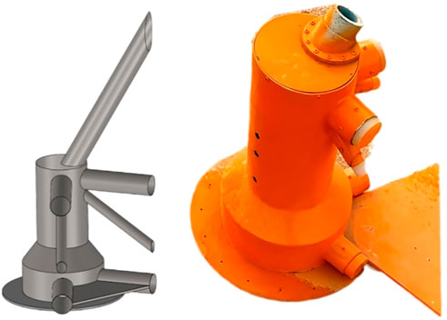
FIGURE 5. Diagram of connection scheme.
Parameters of the mooring cables
According to the similarity criterion, the parameters of each mooring cable scheme can be determined. The full anchor chain scheme can find anchor chain with similar line weight and axial stiffness. But it is difficult to ensure that the stiffness and other characteristics of the polyester cable and the parameters adopted by the floating offshore wind turbine entity are completely scaled according to the scale ratio. Therefore, we assume that the stiffness of the cable at the scale ratio of 1:50 is infinite. The stiffness of the whole mooring system is simulated by adding a calculated spring to the end of the cable. The model of hybrid mooring cable scheme is shown in Figure 6. The specific parameters of the cables are shown in Table 4 and Table 4.
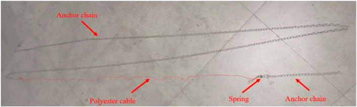
FIGURE 6. The model of hybrid mooring cable scheme.
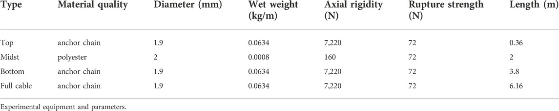
TABLE 4. Model parameters of hybrid mooring cable scheme. Model parameters of full anchor chain scheme.
Experimental equipment and parameters
The experimental equipment includes a wave maker, a wave gauge, and a 6 D.O.F. (six degree of freedom) monitor and tension sensors. The layout position is shown in Figure 7.
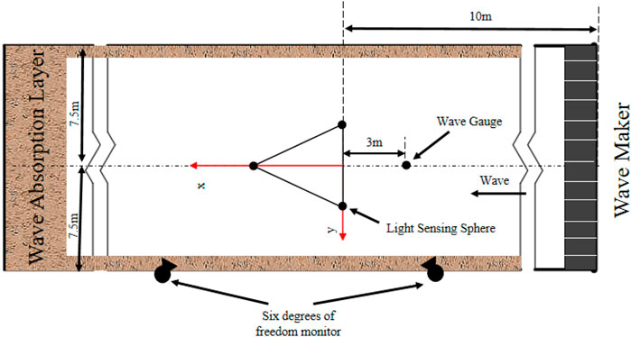
FIGURE 7. Layout diagram of floating offshore wind turbine with the wave direction of 0°.
The wave gauge is used to monitor, measure and record the change of wave surface. Figure 8 shows the capacitive wave gauge used in the experiment. The range of the wave gauge is from -250 mm to 250 mm, and the error is 0.5%. The wave gauge needs to be calibrated before it is used. After calibration, the height meter is placed at 3 m in front of the experiment region.
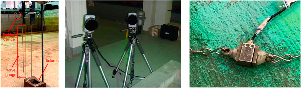
FIGURE 8. Capacitive wave gauge. 6 D.O.F. monitor. Tension sensor.
The motion responses of the floating offshore wind turbine are measured by the 6 D.O.F. measurement system. The measurement ranges of the system are from 180° to 180° for yaw, 90°–90° for pitch and roll, 10 m–10 m for surge and sway, and 1 m–1 m for heave. The errors of yaw, pitch and roll are from 0.1° to 0.1°. The errors of surge, roll and heave are from -2 mm to 2 mm. Figure 8 is the 6 D.O.F. monitor used in the experiment.
Tension sensors are used to measure the tensions of mooring cables. The maximum measurement value of the tension sensor is 50 kg, and the error is 0.25%. The tension sensor needs to measure the initial value before it is used, which is convenient for subsequent data processing. Figure 8 is the tension sensor used in the experiment.
Equivalent simulation of wind load
In the experiment, the ducted fan is used to equivalent the real wind turbine, and the principle is simplified wind load borne by the wind turbine to the reverse thrust exerted on the floating body when the ducted fan starts. A balance weight ring is loaded on the top of the floating body to restore the real center of gravity.
Before the experiment, it is necessary to calibrate the force of the ducted fan according to the wind speed conditions of the floating offshore wind turbine in the real environment. It shows that the maximum static thrust is 9.6 N. When the floating offshore wind turbine works, the thrust of the ducted fan is controlled by the remote control equipment to equivalent the real wind, which will affect the motion responses of the floating offshore wind turbine. By the time, the ducted fan can rotate itself according to the wind direction. Figure 9 is the ducted fan and the remote control equipment, and Figure 10 is the wind speed–thrust curve.
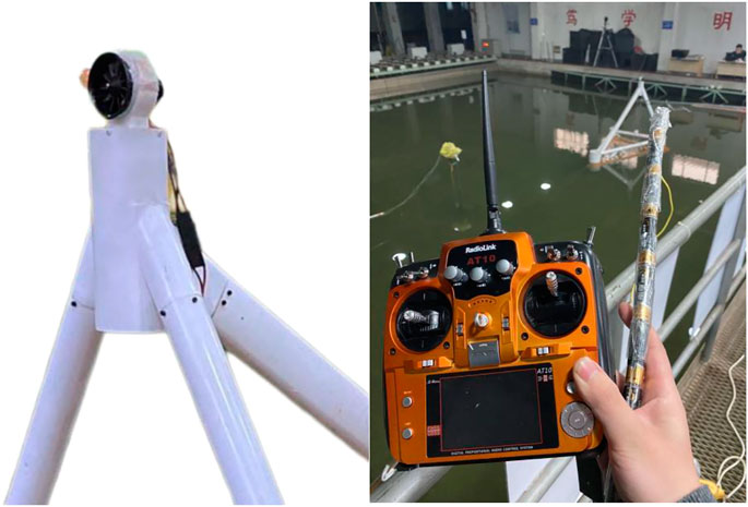
FIGURE 9. The ducted fan and the remote control equipment.
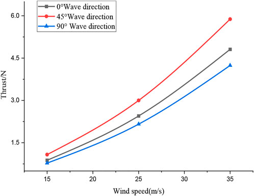
FIGURE 10. The wind speed—thrust curve.
Experiment conditions
There are seven regular waves conditions tested in the experiment, includes two wave heights, six periods and two wind speeds. The experimental conditions are shown in Table 5.
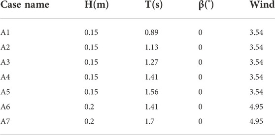
TABLE 5. Experimental conditions.
Analysis of the mooring system characteristics of the new floating offshore wind turbine
Natural period and decay rate
Before carrying out the experiment of the mooring system characteristics, it is necessary to make static water free decay test for the floating offshore wind turbine to study the inherent motion characteristics. Applying torque to the floating offshore wind turbine manually to make it oscillate freely, the natural periodic parameters were obtained by the 6 D.O.F. monitor.
The natural period of roll motion response is 10.61 s, the decay rate is 63.60%, the damping ratio is 7.18%. The natural period of pitch motion response is 29.63 s, the decay rate is 16.39%, the damping ratio is 27.66% The natural period of heave motion response is 22.03 s, the decay rate is 42.47%, the damping ratio is 13.51%. The natural periods of the floating offshore wind turbine are shown in Figure 11. The comparison between the model and the prototype are shown in Table 6, errors in motion response is less than 3%.
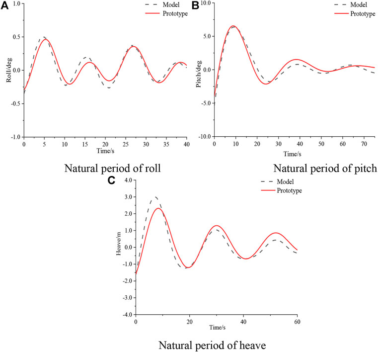
FIGURE 11. Natural period of the floating offshore wind turbine. (A). Natural period of roll (B). Natural period of pitch. (C). Natural period of heave.
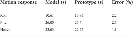
TABLE 6. The comparison between the model and the prototype.
Analysis of mooring stiffness
Setting one end of the mooring cable fixed at the anchor point, and other end fixed at cable hole. Then, the projection length of the mooring cable is changed by moving the position of the guide cable hole to calculate the mooring cable force along the projection length and height direction. The stiffness characteristics of mooring cables along the length and height directions are shown in Figure 12 1) and Figure 12 (b). When the projection length is less than 300 m, the mooring cable is catenary mooring cable, and the stiffness of the mooring line is mainly affected by the weight of the mooring cable. When the projection length is greater than 300 m, the mooring cable is taut mooring cable, and the stiffness of the mooring cable is mainly determined by its own material stiffness.
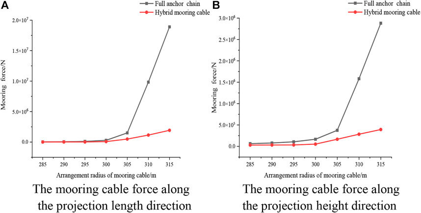
FIGURE 12. Single mooring cable projection lengthwise stiffness characteristics. (A) The mooring cable force along the projection length direction. (B) The mooring cable force along the projection height direction.
Analysis of motion responses
The pitch and heave motion responses of the floating offshore wind turbine with different mooring cable schemes in 45 m working water depth are compared and analyzed.
Figure 12 is the comparison of pitch and heave motion responses of the floating offshore wind turbine at A6 condition, corresponding to the actual wave condition is H = 10 m, T = 10 s. It can be seen from Figure 13 1) that when the mooring cable adopt the full anchor chain scheme, the pitch amplitude is smaller, the amplitude is 3.68°, and that of the hybrid mooring cable scheme is 4.85°, with a difference of 31.79%. It can be seen from Figure 13 2) that the heave motion response of the floating offshore wind turbine is similar to the pitch motion response, and the difference between the two schemes is 6.05%.
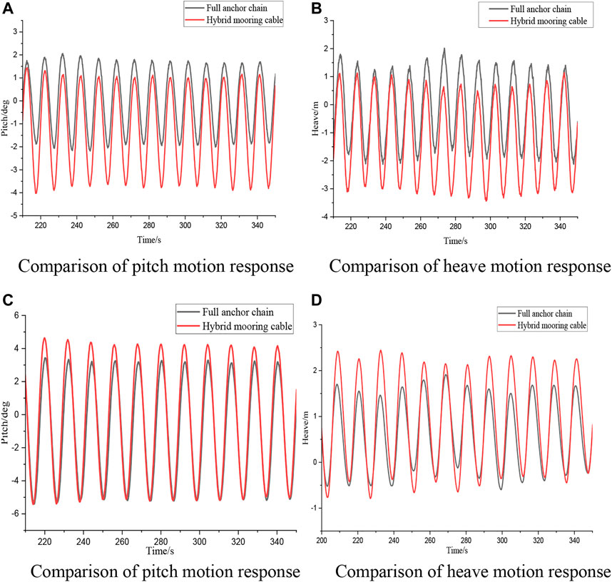
FIGURE 13. Comparison of pitch and heave responses of the floating offshore wind turbine. (A) Comparison of pitch motion response. (B) Comparison of heave motion response. (C) Comparison of pitch motion response. (D) Comparison of heave motion response.
Figure 13 is the comparison of pitch and heave motion responses of the floating offshore wind turbine at A7 condition, corresponding to the actual wave condition is H = 10 m, T = 12 s. It can be seen from Figure 13 1) that when the mooring cable adopt the full anchor chain scheme, the pitch amplitude is small, the amplitude is 8.15°, and that of the hybrid mooring cable scheme is 10.02°, with a difference of 22.94%. It can be seen from Figure 13 2) that the heave motion response of the floating offshore wind turbine is similar to the pitch motion response, and the difference between the two schemes is 26%.
Analysis of mooring force
The mooring force of the different mooring cable schemes are compared and analyzed at the same water depth and working condition. Figure 14 is comparison of force of the mooring system.
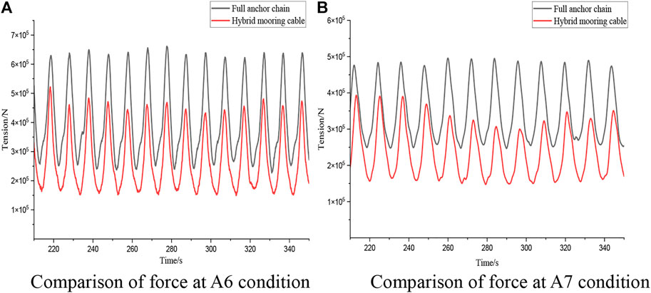
FIGURE 14. Comparison of force of the mooring system. (A). Comparison of force at A6 condition (B). Comparison of force at A7 condition.
Figure 14A is the comparison of the mooring force at A6 condition. It shows that when the mooring cable adopts the full anchor chain scheme, the L6 mooring force is larger than that of the hybrid mooring cable scheme. The maximumforce of the full anchor chain scheme is 6.61 × 10⁵ N, and the maximum force of the hybrid mooring cable scheme is 5.22 × 10⁵ N, the difference is 26.77%.
The results of A7 condition are similar to that of A6 condition. The maximum force of the full anchor chain scheme is 4.95 × 10⁵ N, the maximum tension of the hybrid mooring cable scheme is 3.89 × 10⁵ N, the difference is 27.17%.
Analysis of characteristics of mooring system in hybrid mooring cable scheme
The paper studies the characteristics of the mooring system under different pretension and different water depths when adopt the hybrid mooring cable scheme.
Analysis of characteristics of mooring system under different pretension
This chapter studies the motion responses of the floating offshore wind turbine and the characteristics of L5 mooring force under different pretension at 22.5 m water depth. There are five conditions carried out in the experiment, includes A1, A2, A3, A4, A5, corresponding to the actual wave height is H = 7.5 m, and the wave period are 6.5 s, 8 s, 9 s, 10 s, 11 s, respectively.
By adjusting the length of the polyester cable, the average pretension of mooring cable can be changed, to study the influence of the mooring system characteristics in different pretension.
As is shown in Table 7, the length difference of the three mooring cable is 1.5 m, but the pretensions of the three mooring cables are different. The reason is that under N1, N2 conditions, the mooring cable is catenary, and under the N3 condition, the mooring cable is tensioned, which may cause the change of the characteristics of the mooring system.
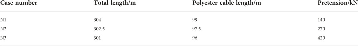
TABLE 7. Parameters of hybrid mooring cable.
Figure 14 is comparison of the characteristics of the mooring system under different conditions. Figure 15 1) is comparison of surge motion response, Figure 15 2) is comparison of heave motion response. Figure 15 3) Comparison of L5 mooring force, Figure 15 4) is comparison of component force. It can be seen that:
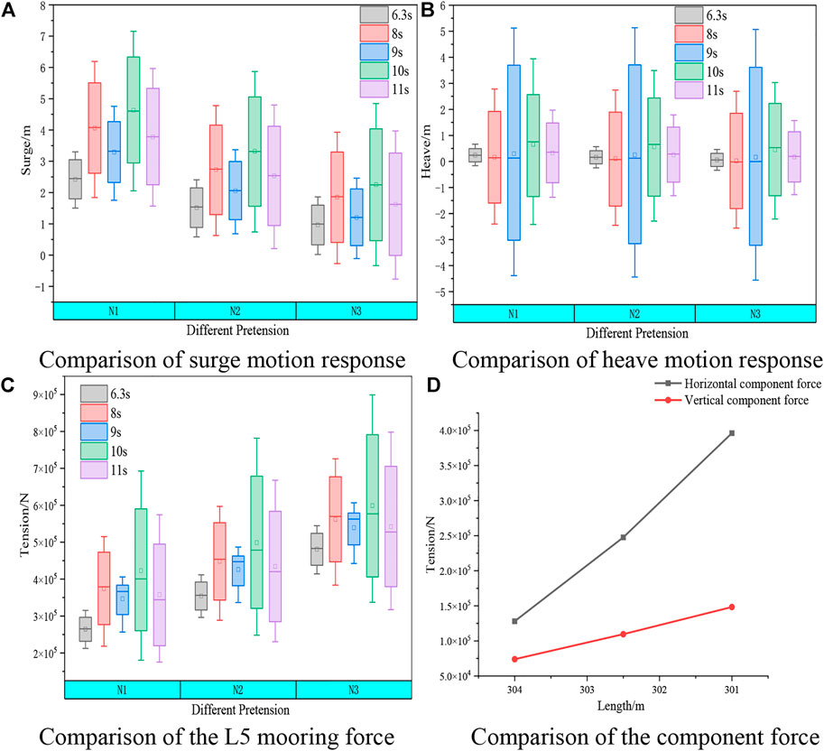
FIGURE 15. Comparison of the characteristics of the mooring system under different pretension. (A). Comparison of surge motion response (B). Comparison of heave motion response. (C). Comparison of the L5 mooring force (D). Comparison of the component force.
Under different pretension, the amplitude of surge and heave motion response of floating wind turbine at the same period is similar. When the wave period is 8 s, 10 s and 11 s, the amplitude of surge response is maximum; When the wave period is 8 s, 10 s, the amplitude of surge response is little. The maximum value and minimum value of surge motion response decreases with the increase of pretension. Heave motion response increases first and then decreases with the increase of period, the change of pretension has little effect on it.
The variation pattern of mooring force is similar to the surge motion response in the same pretension. Mooring force is large in some periods with large surge motion response amplitude; mooring force is little in some periods with little surge motion response amplitude. The maximum value and minimum value of mooring force increases with the increase of pretension.
Combined with the comparison of the component force, it can be found that the vertical component force changes little, which makes the heave motion response of the floating offshore wind turbine changes little under different pretension. While the horizontal component force changes greatly, which makes the surge motion response of the floating offshore wind turbine change obviously.
Analysis of characteristics of mooring system at different depths
This chapter selects A5 condition to study the pitch motion response of the floating offshore wind turbine and L5 mooring force at three water depths of 45 m, 40 m and 22.5 m. Corresponding to the actual wave condition is H = 7.5 m, T = 11 s, β = 0°. Figure 16 is the comparison of the characteristics of the mooring system at different depths.
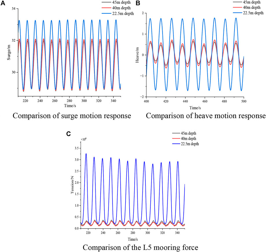
FIGURE 16. Comparison of the characteristics of the mooring system at different depths. (A). Comparison of surge motion response (B). Comparison of heave motion response. (C).Comparison of the L5 mooring force.
Figure 16 1) is the comparison of surge motion response of floating offshore wind turbine in different water depths. It can be seen from the figure that when water depths are 45 m and 40 m, the extreme values and variation amplitudes of the surge motion response are almost the same, and the variation amplitude is 3.47 m. When the water depth is 22.5 m, the extreme value and variation amplitude of surge have increased. The variation amplitude is 4.30 m, which increases by 19% than that at 45m and 40 m water depth.
Figure 16 2) is the comparison of heave motion response of floating offshore wind turbine in different water depths. The characteristics of heave motion response are similar to those of surge motion response, the variation amplitude at 45m and 40 m is 1.04 m. When the water depth is 22.5 m, the variation amplitude is 3.44 m, which increases by 229% than that at 45m and 40 m water depth.
Figure 16 3) is the comparison of L5 mooring force at different water depths. It can be seen from the figure that when water depths are 45 m and 40 m, the maximum mooring force of L5 are 3.52 × 10⁵ N and 3.23 × 10⁵ N, with a difference of 8.96%. When the water depth is 22.5 m, the extreme value of mooring force increases sharply, and the maximum mooring force reaches to 3.26 × 10⁶ N, which increases by 828.6% and 911.78% compared with those of at 45 m and 40 m water depths, respectively.
Figure 17 is comparison of the RAOs at different depths. Combing with the motion response of the floating offshore wind turbine, it can be seen that when the circular frequency is less than 0.7 rad/s, the wave period is larger than 8s, the surge and heave motion of the floating offshore wind turbine at 22.5 m water depth is larger than those at 40 m and 45 m water depth. Which leads to the increase of the motion response at 22.5 m water depth, and further leads to the increase of the mooring cable force.
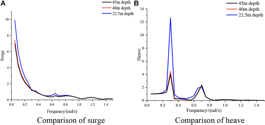
FIGURE 17. Comparison of the RAOs at different depths. (A). Comparison of surge (B). Comparison of heave.
Analysis of characteristics of mooring system in shallow water
Considered that some of these areas have a large tidal range, the water depth is shallow when at a low tide level. Therefore, it is necessary to study the characteristics of the mooring system of the floating offshore wind turbines in shallow water areas.
This chapter studies the motion response of the floating offshore wind turbine and anchor chain tension at 22.5 m shallow water at A5 condition, corresponding to the actual wave condition is H = 7.5 m, T = 11 s, β = 0°. Figure 18 is comparison of the surge and pitch motion response of the floating offshore wind turbine. Figure 18 is comparison of the mooring force of different mooring cable.
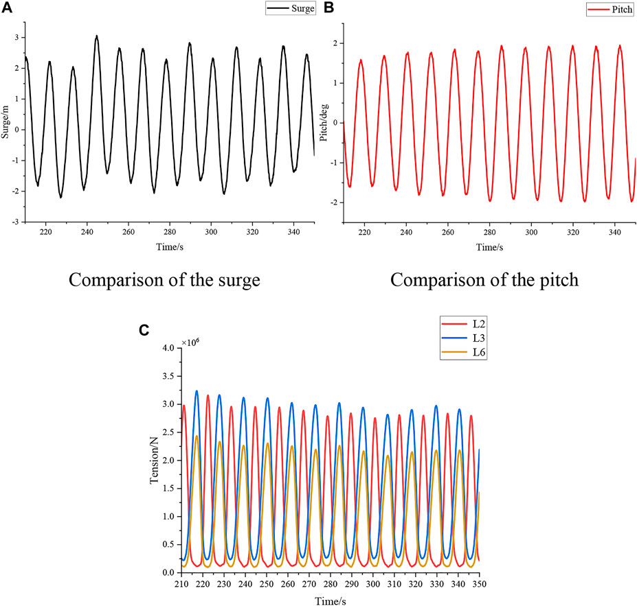
FIGURE 18. The characteristics of mooring system in shallow water. (A) Comparison of the surge. (B) Comparison of the pitch. (C) Comparison of the mooring force of different mooring cable.
Figure 18 1) shows the surge motion response of the floating offshore wind turbine, the change trend decreases first and then increases in period form, the amplitude of surge is 5.03 m. Figure 18 2) shows the pitch motion response of the floating offshore wind turbine, in the time range of 210 s–280 s, the pitch motion response presents a slowly increase trend, and reaches stability at 280 s, the amplitude of pitch is 4°.
Owing to the fact that the mooring system is symmetrically arranged, L2, L3 and L6 mooring cables are selected for force analysis. The analysis of the mooring cable are shown in Figure 18 3) it can be seen that the occurrence time of L2 mooring force is later than that of the L3, L6, because the L2 is on the back of floating body, and it is not affected by wave at first time. From the extreme value of the mooring force, L3 is the largest, L2 is relatively close to it, and L6 is the smallest. The extreme values of the three forces are 3.23 × 10⁶ N, 3.16 × 10⁶ N and 2.43 × 10⁶ N, respectively. Considering that the breaking strength of the mooring cables is 6.00 × 10⁶ N, the safety factor of L3 is 1.86, indicating that the mooring cables under the selected working conditions meet the strength requirements and have a certain amount of saturation.
Conclusion
In this paper, the characteristics of mooring system of a new type floating offshore wind turbine in shallow waters are investigated by model experiment. The motion responses of the floating offshore wind turbine and characteristics of mooring force with different mooring cable schemes under the same mooring system are studied. When it adopts the hybrid mooring cable scheme, the effect of water depth and pretension to the mooring system, and characteristics of the mooring system in shallow water are studied. It is concluded that.
1) The two mooring cable schemes were compared at water depth of 45 m. The motion responses of the floating offshore wind turbine are smaller when the mooring system adopts the full anchor chain scheme, with a difference of about 30%. When mooring system adopts the hybrid mooring cable scheme, there are smaller mooring force, with a difference of about 27%.
2) When the mooring system adopts the hybrid mooring cable scheme:
a) When the pretension of mooring cable is changed, the characteristics of the mooring system is different. The surge motion response at the same wave period is similar for different pretensions, but its maximum and minimum values increase as the pretension increases. At the same pretension condition, the characteristics of mooring force and the surge motion response are similar, but when the pretension increases, the maximum and minimum value of the mooring force is increase. The characteristics of heave motion response are similar at different pretension.
b) When the water depth is changed, the characteristics of the mooring system is different. The surge motion response at 22.5 m water depth is about 19% larger than that at 40 m and 45 m water depth, the heave motion response at 22.5 m water depth is about 229% larger than that at 40 m and 45 m water depth, and the mooring force increased significantly, there are about 828.6% and 911.78% than that at 40 m and 45 m water depth.
c) In the shallow water with depth is 22.5 m, the surge motion response decreases first and then increase in period form, the pitch motion response tends to rise gradually before t = 280 s, and reach stability at 280 s. The mooring force of the L3 is the largest, L2 is relatively close to it, and L6 is the smallest.
Data availability statement
The original contributions presented in the study are included in the article/supplementary material, further inquiries can be directed to the corresponding author.
Author contributions
FH and ZS provided the guidance of experiment and theories. JX took part in the experiment and wrote the paper. HY took part in the experiment, processed and integrated the data. ZY took part in the experiment and corrected the paper.
Funding
This work was financially supported by the National Natural Science Foundation of China (Grant No. 52071161).
Acknowledgments
Thanks to Jiangsu University of Science and Technology for providing experimental site and supports from relevant personnel.
Conflict of interest
The authors declare that the research was conducted in the absence of any commercial or financial relationships that could be construed as a potential conflict of interest.
Publisher’s note
All claims expressed in this article are solely those of the authors and do not necessarily represent those of their affiliated organizations, or those of the publisher, the editors and the reviewers. Any product that may be evaluated in this article, or claim that may be made by its manufacturer, is not guaranteed or endorsed by the publisher.
References
Bach-Gansmo, M. T., Garvik, S. K., Thomsen, J. B., Andersen, M. T., Magnus, T., Stian, K., et al. (2020). Parametric study of a taut compliant mooring system for a FOWT compared to a catenary mooring. J. Mar. Sci. Eng. 8 (6), 431. doi:10.3390/jmse8060431
Benassai, G., Campanile, A., Piscopo, V., and Scamardella, A. (2014). Mooring control of semi-submersible structures for wind turbines. Procedia Eng. 70, 132–141. doi:10.1016/j.proeng.2014.02.016
Brommundt, M., Krause, L., Merz, K., and Muskulus, M. (2012). Mooring system optimization for floating wind turbines using frequency domain analysis. Energy Procedia 24, 289–296. doi:10.1016/j.egypro.2012.06.111
Guo, Z. W., Meng, L., Zhao, Y. S., and He, Y. P. (2016). Experimental methods of offshore floating wind turbine pool model and its research progress. China Mar. Platf. 31 (06), 1–8+14.4.
Huang, W. H., and Yang, R. Y. (2021). Water depth variation influence on the mooring line design for FOWT within shallow water region. J. Mar. Sci. Eng. 9 (4), 409. doi:10.3390/jmse9040409
Lin, Z., Liu, X. L., and Lotfian, S. (2021). Impacts of water depth increase on offshore floating wind turbine dynamics. Ocean. Eng. 224, 108697. doi:10.1016/j.oceaneng.2021.108697
Liu, Z. B., Tang, Y. G., Wang, H., Yang, G., Lin, W. X., and Li, J. W. (2015). Experimental study on the motion characteristics of semi-submersible wind power floating foundation. J. Harbin Eng. Univ. 36 (01), 51–56.
Liu, Z. H., Chen, J. B., Peng, Y. B., Song, Y. P., and Li, J. (2021). Experimental study of a pool model of a large offshore floating offshore wind turbine. Proceedings of the 14th National Conference on Vibration Theory and Applications (NVTA2021021), 172.
McEvoy, P., Kim, S., and Haynes, M. (2021). “Fibre spring mooring solution for mooring floating offshore wind turbines in shallow water,” in Proceedings of the ASME 2021 40th International Conference on Ocean, Offshore and Arctic Engineering. Volume 9: Ocean Renewable Energy. Virtual, Online, June 21–30, 2021 V009T09A029 ASME. doi:10.1115/OMAE2021-62892
Wang, S. L. (2017). Study of hull sinking and longitudinal tilting under shallow water effect. China Water Transp. (Second half Mon. 17, 11–14.
Xu, S., Ji, C. Y., and Guedes Soares, C. (2020). Experimental study on effect of side-mooring lines on dynamics of a catenary moored semi-submersible system. Proc. Institution Mech. Eng. Part M J. Eng. Marit. Environ. 234 (1), 127–142. doi:10.1177/1475090219858820
Yang, J., He, Y. P., Meng, L., Zhao, Y. S., and Wu, H. Y. (2021). Coupled dynamic response on a 6 MW spar-type floating offshore wind turbine under extreme conditions. J. Shanghai Jiao Tong Univ. 55 (1), 21–31.
Yang, R. Y., Wang, C. W., Huang, C. C., Chung, C. H., and Chen, C. P. (2022). The 1:20 scaled hydraulic model test and field experiment of barge-type floating offshore wind turbine system. Ocean. Eng. 247, 110486. doi:10.1016/j.oceaneng.2021.110486
Zhang, W. (2019). The effect of shallow water effect on ships and empirical estimation method. Ship Mar. Eng. 35 (03), 6–12.
Zhang, X., Ni, W. C., Sun, L. P., and Zhang, W. (2020). Experimental investigation of a shuttle tanker in irregular waves with hawser single point mooring system. Ships Offshore Struct. 16 (8), 838–851. doi:10.1080/17445302.2020.1786236
Keywords: shallow water, floating offshore wind turbine, mooring system, hybrid mooring cable, model experiment
Citation: Huo F, Xu J, Yang H, Yuan Z and Shen Z (2023) Study on characteristics of mooring system of a new floating offshore wind turbine in shallow water by experiment. Front. Energy Res. 10:1007996. doi: 10.3389/fenrg.2022.1007996
Received: 31 July 2022; Accepted: 26 September 2022;
Published: 11 January 2023.
Edited by:
Xiao Hang Wang, Nanjing Vocational University of Industry Technology, ChinaReviewed by:
Shan Wang, Universidade de Lisboa, PortugalJunfeng Du, Ocean University of China, China
Copyright © 2023 Huo, Xu, Yang, Yuan and Shen. This is an open-access article distributed under the terms of the Creative Commons Attribution License (CC BY). The use, distribution or reproduction in other forums is permitted, provided the original author(s) and the copyright owner(s) are credited and that the original publication in this journal is cited, in accordance with accepted academic practice. No use, distribution or reproduction is permitted which does not comply with these terms.
*Correspondence: Zhongxiang Shen, emhvbmd4aWFuZzA3MzBAMTI2LmNvbQ==