 Wei Gu1
 Shiqiang Li
- 1Electric Power Dispatching and Control Center of State Grid Zhejiang Electric Power Co. Ltd, Hangzhou, Zhejiang, China
- 2Key Laboratory of Modern Power System Simulation and Control & Renewable Energy Technology, Ministry of Education, Northeast Electric Power University, Jilin, China
The coupling relationship between the removal of the fault current and the dissipation of the residual energy of the fault line during the fault isolation process of the multi-port capacitive current-limiting DC circuit breaker prolongs the breaking time of the fault to a certain extent. In order to solve the above problems, this paper proposes a multi-port DC circuit breaker based on dual-capacitor current limiting and energy sinking on the premise of decoupling the fault current attenuation and removal process and the fault line residual energy discharge process. Further reduce the fault breaking time and equipment withstand voltage requirements of the DC circuit breaker. Firstly, the topology and working principle of the proposed circuit breaker are analyzed, and then the parameters in the topology are designed. Then a simulation model is built in the PSCAD/EMTDC simulation platform to verify the fault breaking performance and breaking time. The effect of decoupling the fault current clearing process and the fault line residual energy discharge process on the effectiveness of shortening the fault breaking time is verified.
Introduction
With the high degree of power electronics of the DC power grid, the low inertia nature of the DC system has caused many adverse effects on the development of the fault current (Mokhberdoran et al., 2017a; Choi et al., 2018; Mohan et al., 2021). If the fault is not removed in time, the electrical equipment will be burned and the fault scope will be expanded. The DC Circuit Breaker (DCCB) can quickly and selectively isolate the faulty line, which can effectively solve the above problems and ensure the stable operation of the DC power grid (Meyer and Rufer, 2006; Arman et al., 2014; Martinez-Velasco and Magnussonet al., 2017). However, when the DC circuit breaker operates, the fault current has risen sharply, and the energy storage elements in the network have also accumulated more energy. Therefore, the DC circuit breaker needs to interrupt a larger current in a short period of time, while dissipating more energy (Novello et al., 2011; Wen et al., 2016; Qu et al., 2019). By analyzing the research status of HVDC circuit breakers, this paper studies and proposes innovations on the existing current limiters and multi-port DC circuit breakers. The main research results are as follows.
To meet the future demand of high voltage and large capacity of DC power network, there is great room for the development of multi-port hybrid DCCB with current limiting capability (Zhao et al., 2019; Xu et al., 2019; Han et al., 2019). Reference (Mokhberdoran et al., 2017b) proposes a capacitive commutation type current-limited DCCB in which the FCL and DCCB share the main flow branch, the main current limiter is used to limit the current during the fault removal process, and the main circuit breaker is used to open and close the current-limited DCCB. In reference Wang et al., 2018, although the DCCB has current limiting capability, it may generate overvoltage problems at both ends of the inductor at the early stage of current conversion, threatening the safety of the equipment. Reference Wen et al., 2016 proposes a valve-segment modular design of current-limited DCCB, where the inductor branches are connected in parallel during normal operation to reduce the equivalent impedance and the impact on the dynamic performance of the system, and the inductor branches are connected in series instead of in parallel during fault conditions.
However, it is difficult to expand the main circuit breaker into multi-port form because of the large number of devices used in the main circuit breaker section and the complex structure. Reference Liu et al., 2017 proposes a multi-port current-limiting DCCB that shares the main current limiter and main circuit breaker, but the main circuit breaker needs to open the fault current of all branches, and if some energy can be transferred to other energy storage elements and then consumed separately, the main circuit breaker can be reduced. Electrical requirements. Reference Liu et al., 2019 proposes a typical half-bridge multi-port DC circuit breaker. The main breaking switch adopts an anti-parallel sub-module, and the selection switch adopts a series branch of a thyristor and an IGBT module, so the manufacturing cost is high. Reference A. (Mokhberdoran et al., 2018a) considers the effect of MP-DCCB and the inherent leveling resistance in the line on suppressing the development of fault current, but the excessively large current limiting inductance will affect the steady-state characteristics of the system during normal operation. At the same time, the energy storage in the current limiting inductor increases the energy consumption demand of the arrester and reduces the decay rate of the fault current. Reference A. (Mokhberdoran et al., 2018b) takes four DC lines sharing one MPCB as an example, and proves that using one unidirectional current conversion path and one EAP for multiple DC lines can optimize the number of components, simplify the EAP structure, and effectively improve economy and flexibility.
Although the above research can achieve rapid fault removal and isolation, there is still room for further improvement in terms of equipment integration, steady-state loss, and manufacturing costs. This paper proposes a multi-port DC circuit breaker topology based on dual-capacitor current limiting and energy sinking by improving the topology of the multi-port DC circuit breaker. The decay process of the fault current is decoupled from the energy discharge process of the energy storage element in the fault line, thereby shortening the time for the DC circuit breaker to isolate the fault line. At the same time, the arrester is no longer used for energy dissipation, but the energy of the fault current is temporarily stored in the capacitor. After the fault is removed, the excess energy is released through the discharge circuit, which further shortens the fault isolation time and equipment withstand voltage requirements of the DC circuit breaker. Finally, the function of the proposed circuit breaker is verified by building a DC grid model in the simulation software. The simulation results prove the effectiveness of decoupling the decay process of the fault current and the energy discharge process of the energy storage element in the fault line to shorten the fault isolation time, which can provide a new idea for the research of DC circuit breakers.
Circuit breaker topology and operating principle IGBT devices
Circuit breaker topology design
The topology of the proposed multi-port DC circuit breaker based on double capacitor current limiting and energy collection (DC CL&EC MP-DCCB) is shown in Figure 1. The topology consists of five main branches, which are low loss branch, voltage regulator and sink branch, current transfer and current limiting branch, energy dissipation branch and state recovery branch.
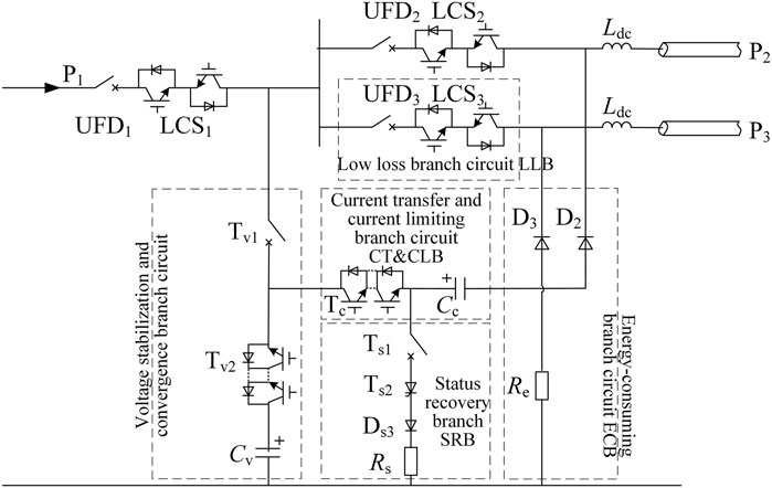
FIGURE 1. DC CL and EC MP-DCCB topology structure.
In Figure 1, the low loss branch (LLB) is a series connection of an ultra-fast mechanical switch UFD and a double-controlled load transfer switch LCS, which is responsible for the delivery of DC operating current during normal system operation and the transfer of auxiliary fault current to the current transfer and current limiting branch when a line short circuit fault occurs on the DC side. Voltage stabilizing and current-collection branch (VS and CCB) consists of a mechanical switch Tv1 and a small number of fully controlled valves Tv2 and voltage stabilizing and current-collection capacitors Cv that can withstand large voltages and are inexpensive. The role of this branch is twofold: first, it is responsible for stabilizing the output voltage on the DC side during steady-state operation of the system; second, it temporarily stores the fault current energy when clearing the DC side fault, and then releases the excess energy after the fault current is cleared. The current-transferring and current-limiting branch (CT and CLB) is composed of a fully controlled valve group Tc and a current-limiting capacitor Cc in series, which is used to provide a current path during fault removal and to limit the growth rate of the fault current by using the current-limiting capacitor Cc. The energy consuming branch (ECB) consists of a diode and an energy dissipation resistor Re, which is used to consume the energy stored in the fault line after the ultra-fast mechanical switch connected to the fault line can withstand the high voltage; the state recovery branch consists of a mechanical switch Ts1, a semi-controlled thyristor switch Ts2, a diode Ds3 and a recovery resistor Rs. This branch is used to consume the energy stored in the current-limiting capacitor Cc after the capacitor Cv is restored to about the system-level voltage, so that the capacitor Cc returns to the zero state.
Analysis of the working principle of circuit breaker
Take the three-port form of DC CL&EC MP-DCCB shown in Figure 1 as an example to illustrate the working principle of the proposed circuit breaker, whose installation position in the four-terminal DC network and the location of short-circuit fault occurrence are also shown in Figure 2.
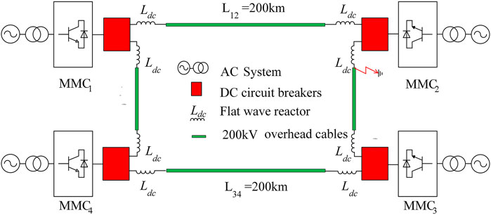
FIGURE 2. Four-terminal DC network.
Suppose t0 moment line L23 near the converter station MMC2 end of a single-pole ground short-circuit fault, multi-port DC circuit breaker P1 port connected to the converter station MMC2, P2 port connected to line L12, P3 port connected to line L23, the specific workflow of the proposed circuit breaker isolation fault line is shown in Figure 3, the action timing sequence is shown in Figure 4, the specific working principle is described below.
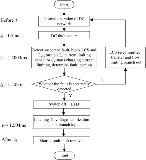
FIGURE 3. Multi-port DC circuit breaker action flow.
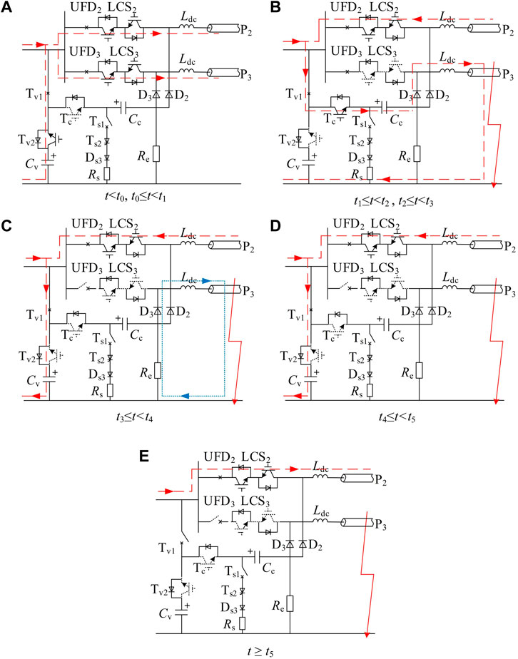
FIGURE 4. Fault Isolation Action Timing.
Normal working condition
When the system is in normal operation (t < t0), the DC circuit breaker carries out power transmission through the internal low-loss branches, at this time, each ultra-fast mechanical switch UFD and load transfer switch LCS is on, switches Tv1 and Tv2 are on, and the voltage stabilization and current convergence branches are connected to the DC system, at this time, capacitor Cv is used as the voltage stabilization capacitor. When the DC output voltage of the converter station fluctuates in a small range, the regulator and sink branch can play the role of stabilizing the DC output voltage and improving the quality of the DC power supply. The transfer and current-limiting branch are in the open-circuit state, and no current flows through the energy-consuming branch. The current path in normal operation is shown in Figure 4A.
DC line short circuit
1) t0≤t < t1
After a 0.3 ms delay, the relay protection device detects a suspicious fault in the DC system at the moment t1. t0≤t < t1, the DC fault current grows freely, and the fault current path is the same as the normal working state of the DC system, and the current path is shown in Figure 4A.
2) t1≤t < t2
At the moment of t1, the fully controlled valve group Tc of the transfer and current limiting branch is given a signal, while the fully controlled valve group Tv2 of the voltage regulator and current sink branch is blocked and the load transfer switch LCS3 is turned off, at which time the current limiting capacitor Cc starts charging and suppresses the growth rate of the fault current. The purpose of blocking valve Tv2 is to prevent the voltage regulator and current sink capacitor Cv of the same voltage level as the system from discharging to the fault point. Again, due to the extremely short opening time of the power electronic switch, the above actions are considered to occur simultaneously during the analysis. If the fault is accurately detected at the moment t2, the subsequent actions are carried out, otherwise LCS3 is re-conducted, and the transfer and current limiting branches are withdrawn, and the system returns to normal operation. The current path at this stage is shown in Figure 4B.
3) t2≤t < t3
The fault detection phase ends at t2 and the fault location is accurately detected, at which time the ultra-fast mechanical switch UFD3 directly connected to the faulty branch is tripped, the current limiting capacitor continues to charge, and the fault current limiting capability is further enhanced. By the time UFD3 reaches the rated opening distance at the moment t3, it can provide sufficient electrical strength for the removal of the faulty line, and the current path in the time period t2≤t < t3 is also shown in Figure 4B.
4) t3≤t < t4
At the moment of t3, UFD3 opens to the rated breaking position, at which time a shutdown signal is applied to the transfer and current limiting branch switch Tc, and the fault current is passed through the diode of the voltage regulator and sink branch and capacitor Cc to form a circuit and store the fault current energy in capacitor Cc. At this point, capacitor Cc exists in the fault circuit as a sink capacitor, and the current path is shown as the red dashed line in Figure 4C. At the same time, the energy stored in the flat reactor on the fault line is released through the energy dissipation branch - flat reactor - fault grounding point circuit, and the current path is shown as the blue dashed line in Figure 4C. Thus, the decoupling of fault current decay and fault line energy release is achieved, which can significantly shorten the action time of DC circuit breaker to remove the DC fault line.
5) t ≥ t4
The energy storage element on the faulty line ends at t4, the faulty line current drops to 0, and the faulty line completes its isolation work. t5, the fault current on the voltage stabilization and energy sink branch drops to 0, at which time the mechanical switch Tv1 is available for arc-free breaking, and the non-faulty line resumes normal operation. t4≤t < t5 time period and the current path after t5 moment are shown in Figures 4D, E respectively.
Circuit breaker key parameters design
As the DC circuit breaker working principle research mainly focuses on the fault opening process, for the energy dissipation process of the internal energy storage elements of the circuit breaker after the completion of the fault opening, in order to restore the fault line to normal operation as soon as possible for transient faults, the recovery resistance Rs can be taken as a smaller value to reduce the current limiting capacitor Cc state recovery loop (current limiting capacitor Cc-switch Ts1, Ts2, Ds3, recovery resistance Rs - energy dissipation resistance Re) of the time constant. Therefore, the key components in the proposed multi-port DC circuit breaker topology include current-limiting capacitor Cc, voltage regulator and sink capacitor Cv, and energy dissipation resistor Re. For the current-limiting capacitor Cc in this paper, the parameter design principle is the same as that of the common transfer capacitor C (Wang et al., 2019). Therefore, the value of the current-limiting capacitor Cc is set to 215μF, and the design of the other two key parameters is analysed below.
Voltage regulator and sink capacitor Cv design
During normal system operation, the voltage regulator and sink capacitor Cv can be equated to a large supply of system-level voltage, and there is not much significance in discussing its parameters in steady state. While during short circuit fault removal on the DC side of the line, the parameters of capacitor Cv are designed to directly affect the time required for the fault current to flow to capacitor Cv to eventually drop to 0 after the ultra-fast mechanical switch connected to the fault line is fully tripped and the peak voltage that capacitor Cv eventually reaches, i.e., the stage shown in Figure 4C. The equivalent circuit for this stage and its simplified circuit are shown in Figure 5, where U is the equivalent DC voltage source for the converter station and Ldc is the flat wave reactor.
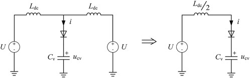
FIGURE 5. Parametric analysis of capacitor Cv equivalent circuit and its simplified circuit.
The following equation can be written from the simplified circuit in Figure 5.
The analysis shows that the smaller the capacitor Cv parameter is, the faster the capacitor absorbs the fault current, the shorter the time for the fault current to drop to 0, but at the same time the higher the peak voltage that the capacitor eventually reaches. The model is simulated in PSCAD/EMTDC software, and the results are shown in Figure 6. In Figure 6A, it can also be seen that when the capacitor Cv parameter is taken as 50 μF, the fault current can be decayed to 0 in 5.8 ms after the fault occurs, which takes the shortest time, but the peak voltage of capacitor Cv reaches 373 kV, which seriously affects the insulation level and insulation cost of the equipment. The decay time of the fault current increases slightly as the value of the capacitance Cv parameter is gradually increased. When the capacitance Cv parameter reaches 200 μF, the fault current excision time remains basically unchanged, and only increases by 0.8 ms compared with the fault current excision time required for capacitance Cv parameter taken as 50 μF, but the peak voltage of capacitance Cv decreases from 373 kV to 259 kV. The influence of the final peak voltage change is significantly reduced. Through the above analysis, considering the fault current excision time, the peak voltage of capacitor Cv and the insulation effect of capacitance parameter on the equipment, the value of voltage regulator and sink capacitor Cv parameter is taken as 200 µF in this paper.
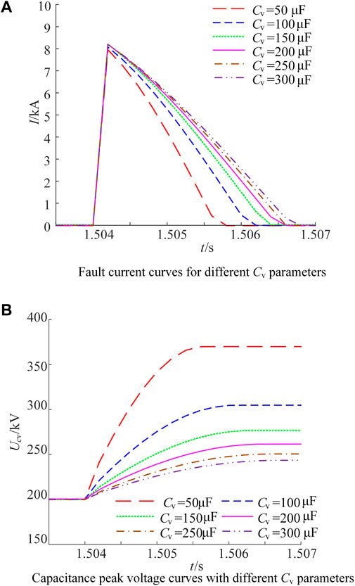
FIGURE 6. Fault current and peak capacitor voltage curves for different Cv parameters.
Energy-consuming resistor Re design
The energy dissipation resistance Re mainly affects the energy release time of the energy storage elements in the fault line after the fault current is transferred to the voltage regulator and sink branch, which means that it affects the isolation time of the fault line. To meet the rapidity requirements of the circuit breaker, the model is built in the PSCAD/EMTDC software for simulation analysis, and the fault line current curves under different energy dissipation resistance Re parameters are shown in Figure 7. As can be seen from Figure 7, the decay time of the current on the faulty line is gradually shortened when the energy dissipation resistor Re parameter is gradually increased. However, when the energy dissipation resistor Re increases to 150 Ω, the fault line can be isolated 4.8 ms after the fault occurs. When the resistance value continues to increase, the isolation time of the fault line basically no longer changes. In summary, the energy dissipation resistor Re parameter in this paper is taken as 150 Ω.
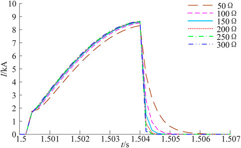
FIGURE 7. Fault line current curves for different energy dissipation resistance Re parameters.
Simulation analysis
The proposed circuit breaker function is verified by building the four-terminal DC network model shown in Figure 2 in PSCAD/EMTDC simulation software. The parameters of each converter station are set as shown in Table 1, and the parameters of DC circuit breaker components are shown in Table 2: line parameters are r0 = 0.01 Ω/km, l0 = 0.82 mH/km, and DC line flat wave reactance is taken as 20 mH. It is assumed that a single-pole short circuit fault occurs at the first end of L23 when the system is in stable operation for 1.5 s. The three-port DC circuit breaker connected to MMC2 of the converter station is used as an example to verify the opening performance and fault opening time of the circuit breaker topology proposed in this paper.
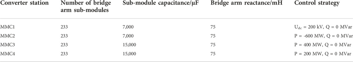
TABLE 1. Converter station parameters.
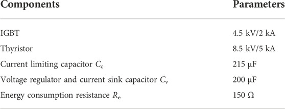
TABLE 2. DC circuit breaker parameters.
Open capacity verification
Figure 8 shows that the current flow in each branch inside the proposed multi-port DC circuit breaker during the opening of the breaker for DC fault current.
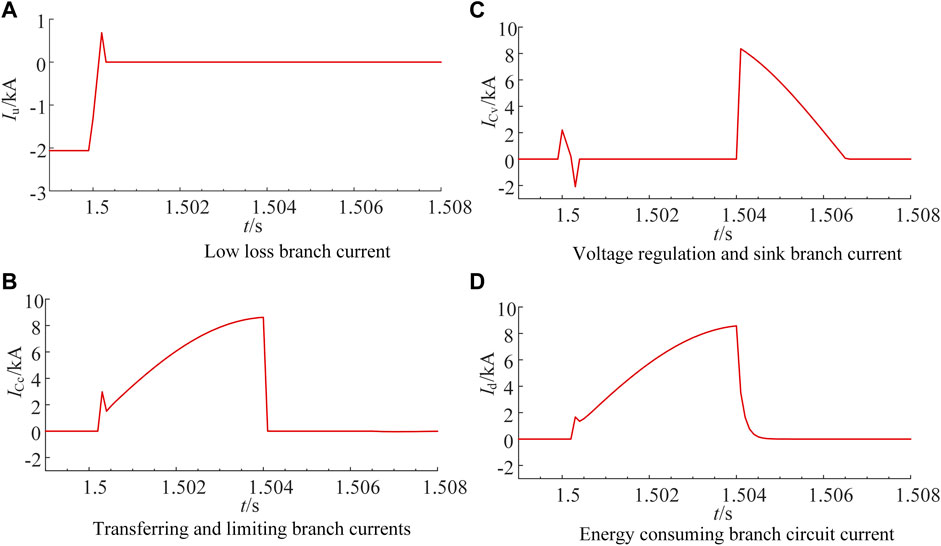
FIGURE 8. DC fault current opening and closing curves.
Figure 8A shows the current situation of the low-loss branch, steady-state operation, the converter station MMC2 and MMC3 for the receiving end of the converter station, the operating current flow on line L23 for the converter station MMC3 to MMC2, after the occurrence of a fault, the current on line L23 first decays rapidly to 0 and then increases in the reverse direction to 0.68 kA, to 1.5003 s when the transfer and current-limiting branch is put in. The fault current is transferred to the transfer and current-limiting branch, and the current condition of this branch is represented by the current ICc flowing through the current-limiting capacitor Cc, and the ICc current curve is shown in Figure 8B. At 1.5003 s, the transfer and current limiting branch current increases rapidly to 0.68 kA. Due to the presence of current limiting capacitor Cc, the fault current increases to 0.68 kA and then decreases slightly after the fault current charges the current limiting capacitor continuously, and the current limiting capacity of the current limiting capacitor gradually increases. The rise rate of the fault current gradually decreases to 1.504 s fault line connected to the ultra-fast mechanical switch breaks to the rated open position, transfer, and current limiting branch out, ICc current value quickly reduced to zero. Thereafter the energy contained in the fault current is divided into two parts: one is that the feeder current of other converter stations cannot be changed instantaneously due to the role of inductive elements in the network. This part of the current energy is temporarily stored by the sink capacitor, and the feeder current of the converter station rapidly decreases to zero within a few milliseconds, after which the non-faulty part of the network gradually resumes normal operation to reduce the impact of the fault, as shown in Figure 8C. The current fluctuation at 1.5 s in this curve is caused by the short-time discharge and charging of the voltage regulator and sink capacitor at the moment of the fault, but the branch is removed in time 0.3 ms after the fault to prevent further discharge of the voltage regulator and sink capacitor. Second, the energy stored in the flat wave reactor in the faulty line, this part of energy is released through the loop formed by the energy dissipation branch and the faulty line. The current situation during this time is shown in Figure 8D for the part t > 1.504 s. As can be seen from Figure 8D, the fault branch current completes the energy release of the energy storage element at 1.5048 ms, and the time required to isolate the faulted line is significantly reduced.
Figure 9 shows the use of ABB hybrid DC circuit breaker compared to the current limiting DC circuit breaker CC&CL-HDCCB based on capacitive commutation proposed in literature CUZNER R M et al., 2017 and the resistance-inductance current limiting hybrid DC circuit breaker proposed in literature Wang et al., 2019 fault current under each scheme of LR-HDCCB. Combining with Figure 8, it can be seen that the peak fault current of the circuit breaker proposed in this paper is 8.8 kA, which is 20.7% lower than that of the ABB solution and the breaking time is shorter. Compared with LR-HDCCB, the current limiting capability is slightly insufficient. However, it can be seen from Figure 12 that the voltage across the circuit breaker of the LR-HDCCB is extremely high during the commutation stage, even higher than the system-level voltage. This is caused by the parallel connection of resistance and inductance in the commutation stage, which may cause the ultra-fast mechanical switch to be difficult to break and even cause equipment damage. Compared with CC&CL-HDCCB, the current limiting capability is similar, but the fault clearing time advantage of the scheme proposed in this paper is obvious. From the above analysis, it can be concluded that the multi-port DC circuit breaker proposed in this paper has a good current limiting capability and has the shortest fault breaking time.
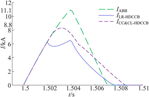
FIGURE 9. Fault current comparison.
Figure 10 shows that the voltage rise of the current limiting capacitor Cc and the sink capacitor Cv during the opening of the proposed circuit breaker for DC line faults.
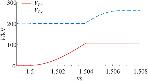
FIGURE 10. Current limiting capacitor and sink capacitor voltage curves.
Among them, the voltage of current-limiting capacitor Cc reaches its peak voltage after the ultra-fast mechanical switch connected to the fault line breaks to the rated position, and its peak voltage is 100 kV, as shown in the red curve in Figure 10. The voltage rise of the sink capacitor Cv is shown in the blue curve in Figure 10. The voltage of the sink capacitor Cv at steady state is approximately the system voltage. The moment the fault occurs, its voltage fluctuates slightly, and then the circuit breaker acts in time, its voltage remains stable until the fault line connected to the ultra-fast mechanical switch breaks to the rated position sink branch re-entered, transfer and current-limiting branch out of operation. Sink capacitor Cv pooling converter station fault current, capacitor Cv voltage gradually increases until the converter station feeder current drops to zero, capacitor Cv voltage reaches its peak value of 260 kV.
Figure 11 shows that the voltage curves at both ends of the main breakout switch of the proposed multi-port circuit breaker. The proposed main breakout switch refers to the IGBT full control switch of the current transfer and current limiting branch and the IGBT full control switch of the voltage regulator and current sink branch.
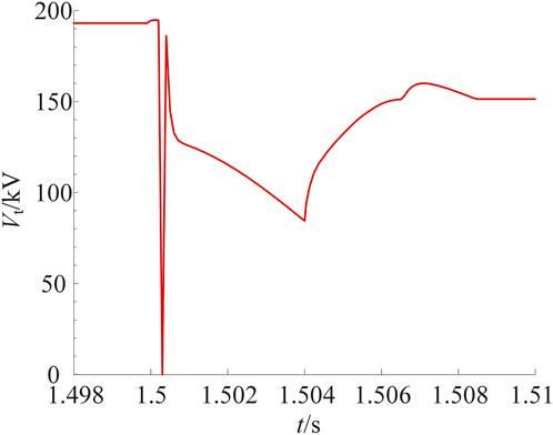
FIGURE 11. Multi-port circuit breaker main breakout switch voltage curve at both ends.
Since the system is operating at steady state when the circuit breaker internal voltage regulator and sink branch is on, current transfer and current limiting branch is open, and capacitor Cv carries the system-level voltage, the current transfer and current limiting branch is first on and then off during DC fault opening and closing, the voltage regulator and sink branch is first off and then on, and the fully controlled switching states of the two branches are complementary, so they are jointly regarded as the main breaking switch of the circuit breaker to observe the voltage conditions at both ends. As can be seen from Figure 11, the main breakout switch (mainly the current transfer and current-limiting branch switch) bears the system-level voltage during steady state. After 0.3 ms after the fault, the transfer branch is triggered and the voltage at both ends of the main breakout switch drops to zero, and then the voltage stabilization and current convergence branch switch is blocked. The main breakout switch (mainly the voltage regulator and sink branch switch) bears the voltage, and then the current limiting capacitor Cc is continuously charged. The voltage across the main breakout switch gradually decreases until the 1.504 s sink capacitor Cv resumes conduction and pools the fault current energy. The voltage of capacitor Cv gradually increases to a peak voltage of 260 kV, and the voltage across the main breakout switch (mainly the current transfer and current limiting branch switch) increases to a final voltage of 156 kV. Accordingly, the number of devices for the IGBT full control switch of the current transfer and current limiting branch switch and the IGBT full control switch of the voltage regulator and current sink branch switch is calculated.
Figure 12 shows a comparison of the voltage across the circuit breaker during fault removal for each scheme. In the LR-HDCCB scheme, since the capacitor is charged first, then discharged, and then reversely charged to the final voltage, the voltage across the circuit breaker is determined by the arrester voltage and the current-limiting inductor voltage until the arrester consumes energy. In the CC&CL-HDCCB scheme, in the commutation stage, the voltage across the circuit breaker is extremely high due to the action of the resistance-inductance parallel part. With the gradual input of the inductance, the voltage across the circuit breaker gradually decreases until the voltage jumps again in the energy consumption stage of the arrester. The circuit breaker consumes energy through the arrester, and the voltage across both ends gradually drops until the fault is removed. It can be seen from the comparison results that the proposed circuit breaker shortens the operation time and reduces the voltage level during the breaking process of the circuit breaker, which is beneficial to the safe and stable operation of the equipment.
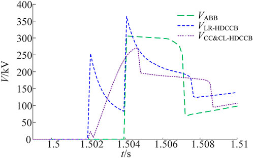
FIGURE 12. Voltage comparison across DC circuit breakers.
Figure 13 shows the comparison of the arrester energy consumption of each scheme. In the figure, the power consumption of the arrester under the ABB scheme is 5250 kJ. In this scheme, because part of the energy is stored in the commutation capacitor, the power consumption of the arrester is reduced to 3684 kJ. In the LR-HDCCB scheme, due to the continuous energy consumption of the resistance-inductive parallel branch in the commutation stage and later, the power consumption of the arrester in this scheme is slightly smaller than 2874 kJ, but there is still the problem of excessive voltage across the circuit breaker in the commutation stage. In the CC&CL-HDCCB scheme, part of the energy is stored in the capacitor during the operation of the circuit breaker, and the energy consumption of the arrester is slightly less than 3305 kJ. Because the final value voltage of the capacitor in this scheme is higher than the system level voltage and much higher than the final value voltage of the capacitor in this scheme, it affects the insulation cost of the equipment. From the above analysis, it can be seen that this solution not only reduces the energy consumption of the arrester, but also takes into account the insulation cost of the equipment, which is beneficial to prolong the service life of the arrester and reduce the cost.
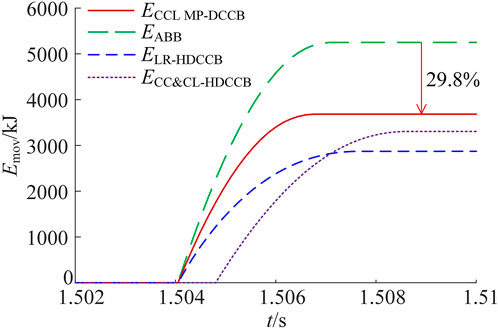
FIGURE 13. Arrester energy consumption comparison.
Fault breaking time check
To calibrate the decoupling of the decay removal process of the fault current from the discharge process of the residual energy of the faulty line to achieve further reduction of the fault opening time of the DC circuit breaker. The simulation of the fault line opening current profile of the multi-port DC circuit breaker proposed in this paper is compared with that of the multi-port DC circuit breaker proposed in the literature Han et al., 2019, and the results are shown in Figure 14.
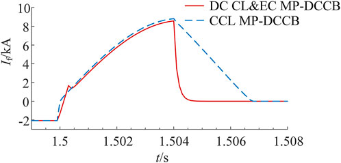
FIGURE 14. Fault line opening and closing time comparison.
It is obvious from Figure 14 that both schemes have the same current limiting effect on the fault current, with the peak fault current at 8.8 kA. However, the multi-port DC circuit breaker topology proposed in this paper decouples the fault current decay process from the fault line energy release process, and the fault line current drops to 0 at 1.5048 s. Compared with the circuit breaker topology proposed in the literature Han et al., 2019, the fault The isolation of the line is completed 2 ms earlier, reducing the time required to isolate the faulty line by about 29.4%. Thus, the effectiveness and necessity of decoupling the decay removal process of the fault current from the discharge process of the residual energy of the faulty line is verified.
Economic analysis
From the simulation results in Figure 8, the peak fault current of the low-loss branch is 2.06 kA and the rated current of IGBT is 2 kA. Considering the current margin, two branches of the low-loss branch need to be connected in parallel, and the number of IGBTs in series in each branch is 20. Because the peak fault current of the transfer and current-limiting branch is 8.6 kA, five branches need to be connected in parallel, and the number of IGBTs in series in this branch needs to be determined according to the voltage at both ends of the branch. As can be seen from Figure 11, the peak withstand voltage of this branch is 193 kV, and considering the engineering conditions and safety margin, the voltage withstand capability of IGBT is 2.25 kV, so the number of IGBTs to be connected in series is 193/2.25 = 86, so the number of IGBTs required for this branch is 86 × 5 = 430. The peak current of the voltage regulator and sink branch is 8.36kA, so this branch needs to be connected in parallel with five branches, and it can be seen from Figure 11 that the peak withstand voltage of this branch is 188kV, and the number of IGBTs need to be connected in series is 188/2.25 = 84, so the number of IGBTs needed for this branch is 84 × 5 = 420.
In the ABB solution: the current peak value of the low-loss branch is 6.26 kA, the LCS needs to be connected in parallel with four branches, and the required number of IGBTs is 80; the peak fault current is 11.1 kA, the main circuit breaker needs to be connected in parallel with six branches, and the main circuit breaker needs to be connected in parallel. The number of IGBTs required by the branch is 6 × 2×300/2.25 = 1,600. The total number of IGBTs required is 1,680. In the LR-HDCCB scheme: the current peak value of the low-loss branch is 6.26 kA, the LCS needs to be connected in parallel with four branches, and the number of IGBTs required is 80; the peak fault current is 6.60 kA, and the main breaking branch needs to be connected in parallel with four branches. The number of IGBTs required for the main breaking branch is 4 × 300/2.25 = 534. The total number of IGBTs required is 614. In the CC&CL-HDCCB scheme: the peak value of the current flowing through the main breaking branch is 8.31 kA, five branches need to be connected in parallel, and the number of IGBTs required is 2 × 5×150/2.25 = 667. The number of thyristors required is 364. If the two-port DC circuit breaker has the same breaking capacity as the circuit breaker in this article, three devices are required, so the number of components of the above circuit breaker needs to be multiplied by three times.
To sum up, the circuit breaker topology proposed in this paper requires a total of 920 IGBTs, which is slightly less economical than the topology proposed in the literature Han et al., 2019, but still better than ABB hybrid DC circuit breakers and capacitor commutation-based circuit breakers, current-limiting DC circuit breakers and resistance-inductance current-limiting hybrid DC circuit breakers. First of all, this paper takes advantage of the advantages of hybrid equipment and adopts the idea that multiple current limiters or circuit breakers at the same DC bus share the main current limiting circuit or breaking circuit, and design a current branch corresponding to n ports and low on-state loss. Secondly, designing the main current limiter by utilizing the advantages of the transfer capacitor in terms of voltage and current resistance level, cost, blocking ability and reliability. Finally, using the full control of IGBT to design the main circuit breaker; adopts the action sequence of current limiting and then breaking to reduce the energy consumption demand of the arrester.
Table 3 shows the economic comparison of each scheme. It can be seen that this scheme not only has a good current limiting effect and improves equipment integration, but also greatly improves the economy.

TABLE 3. Economic comparison.
Conclusion
This paper proposes a multi-port DC circuit breaker based on dual-capacitor current limiting and sink energy, which decouples the decay and removal process of the fault current from the discharge process of the residual energy of the fault line. The transfer branch capacitor is used to achieve the current limiting function, and the voltage regulator and sink branch capacitor provide a path for the source-side fault current after decoupling the circuit and make it decay quickly. The transfer branch capacitor is used to limit the current, the voltage regulator and the sink branch capacitor to provide a path for the source-side fault current to decay quickly. The proposed circuit breaker’s breaking capacity and fault breaking time were verified by building a four-terminal DC network model in the PSCAD/EMTDC simulation software. The analysis of the simulation results shows that the proposed circuit breaker is economically superior. At the same time, the operation time has been improved compared with the capacitor-based multi-port DC circuit breaker, which is conducive to the rapid isolation of DC faults and the recovery of the grid as soon as possible and can provide ideas for the development of DC circuit breaker research. Cuzner and Singh, 2017; Ahmad and Wang, 2019.
Data availability statement
The original contributions presented in the study are included in the article/supplementary material, further inquiries can be directed to the corresponding author.
Author contributions
WG and XL designed the topology of multi-port DC circuit breaker, WY and QH calculated the charging capacitance parameters of circuit breaker, SL and JB verified the topology results by simulation, and carried out a literature review.
Funding
This paper is supported by the Research Project on the Theory and Technology of Dispatching Operation Control of Zhejiang New Power System (SGTYHT/21-JS-226).
Conflict of interest
WG, XL, WY, and QH were employed by the company Electric Power Dispatching and Control Center of State Grid Zhejiang Electric Power Co. Ltd.
The remaining authors declare that the research was conducted in the absence of any commercial or financial relationships that could be construed as a potential conflict of interest.
Publisher’s note
All claims expressed in this article are solely those of the authors and do not necessarily represent those of their affiliated organizations, or those of the publisher, the editors and the reviewers. Any product that may be evaluated in this article, or claim that may be made by its manufacturer, is not guaranteed or endorsed by the publisher.
References
Ahmad, M., and Wang, Z. (2019). A hybrid DC circuit breaker with fault-current-limiting capability for VSC-HVDC transmission system. Energies 35 (06), 2388–1045. doi:10.3390/en12122388
Arman, H., Jurgen, H., and Bjorn, J. (2014). Technical assessment of load commutation switch in hybrid HVDC breaker. IEEE Trans. Power Electron. 30 (10), 5393–5400. doi:10.1109/TPEL.2014.2372815
Choi, H., Jeong, I., and Choi, I. (2018). Stability improvement of DC power system According to applied DC circuit breaker combined with fault current limitation characteristics of superconductivity. IEEE Trans. Appl. Supercond. 28 (7), 1–4. doi:10.1109/tasc.2018.2841931
Cuzner, R. M., and Singh, V. (2017). Future shipboard MVdc system protection requirements and solid-state protective device topological tradeoffs. IEEE J. Emerg. Sel. Top. Power Electron. 5 (1), 244–259. doi:10.1109/jestpe.2016.2638921
Han, N. Z., Fan, Q., Jia, X. F., Qiu, P., Xu, F., Lu, Y., et al. (2019). A multi-port DC circuit breaker with current limiting capability. Chin. J. Electr. Eng. 39 (17), 5172–5181+5298. doi:10.1049/icp.2022.1379
Liu, G. R., Xu, F., Xu, Z., Zhang, Z., and Tang, G. (2017). Assembly HVDC breaker for HVDC grids with modular multilevel converters. IEEE Trans. Power Electron. 32 (2), 931–941. doi:10.1109/tpel.2016.2540808
Liu, W., Liu, F., Zhuang, Y., Zha, X., Chen, C., and Yu, T. (2019). A multiport circuit breaker-based multiterminal DC system fault protection. IEEE J. Emerg. Sel. Top. Power Electron. 7 (1), 118–128. doi:10.1109/jestpe.2018.2885547
Martinez-Velasco, J. A., and Magnusson, J. (2017). Parametric analysis of the hybrid HVDC circuit breaker. Int. J. Electr. Power & Energy Syst. 84, 284–295. doi:10.1016/j.ijepes.2016.06.006
Meyer, J., M., and Rufer, A., A. (2006). A DC hybrid circuit breaker with ultra-fast contact opening and integrated gate-commutated thyristors (IGCTs). IEEE Trans. Power Deliv. 21 (2), 646–651. doi:10.1109/tpwrd.2006.870981
Mohan, M. (2021). A comprehensive review of DC fault protection methods in HVDC transmission systems[J]. Prot. Control Mod. Power Syst. 6 (1), 1–20. doi:10.1186/s41601-020-00173-9
Mokhberdoran, A., Carvalho, A., Silva, N., Leite, H., and Carrapatoso, A. (2017a). Application study of superconducting fault current limiters in meshed HVDC grids protected by fast protection relays. Electr. Power Syst. Res. 143, 292–302. doi:10.1016/j.epsr.2016.09.008
Mokhberdoran, A., Carvalho, A., Silva, N., Leite, H., and Carrapatoso, A. (2017b). Design and implementation of fast current releasing DC circuit breaker. Electr. Power Syst. Res. 151, 218–232. doi:10.1016/j.epsr.2017.05.032
Mokhberdoran, A., Gomis-Bellmunt, O., Silva, N., and Carvalho, A. (2018a). Current flow controlling hybrid DC circuit breaker. IEEE Trans. Power Electron. 33 (2), 1323–1334. doi:10.1109/tpel.2017.2688412
Mokhberdoran, A., Hertem, D. V., Silva, N., Leite, H., and Carvalho, A. (2018b). Multiport hybrid HVDC circuit breaker. IEEE Trans. Ind. Electron. 65 (1), 309–320. doi:10.1109/tie.2017.2719608
Novello, L., Baldo, F., Ferro, A., Maistrello, A., and Gaio, E. (2011). Development and testing of a 10-kA hybrid mechanical–static DC circuit breaker. IEEE Trans. Appl. Supercond. 21 (6), 3621–3627. doi:10.1109/tasc.2011.2169411
Qu, L., Yu, Z., Song, Q., Yuan, Z., Zhao, B., Yao, D., et al. (2019). Planning and analysis of the demonstration project of the MVDC distribution network in Zhuhai. Front. Energy 13 (1), 120–130. doi:10.1007/s11708-018-0599-2
Wang, J. J., and Wang, Z. X. (2019). A new hybrid high-voltage DC circuit breaker topology with current limiting capability. Power Syst. Autom. 39 (10), 143–149. doi:10.3390/en12122388
Wang, Y. Z., Yuan, Z. C., Wen, W. J., Ji, Y., Fu, J., Li, Y., et al. (2018). Generalised protection strategy for HB-MMC-MTDC systems with RL-FCL under DC faults. IET Gener. Transm. &. Distrib. 12 (5), 1231–1239. doi:10.1049/iet-gtd.2016.1943
Wen, W., Huang, Y., Sun, Y., Wu, J., Al-Dweikat, M., and Liu, W. (2016). Research on current commutation Measures for hybrid DC circuit breakers. IEEE Trans. Power Deliv. 31 (4), 1456–1463. doi:10.1109/tpwrd.2016.2535397
Xu, J. Z., Zhang, J. Y., and Li, S. (2020). A capacitance-limited DC circuit breaker topology and its application in DC power networks. Chin. J. Electr. Eng. 40 (08), 2618–2628. doi:10.13334/j.0258-8013.pcsee.190129
Keywords: flexible DC power grid, HVDC circuit breakers, topology structure, multi-port, consumption of clean energy
Citation: Gu W, Lou X, Yin W, Huang Q, Li S and Bian J (2023) Multi-port DC circuit breaker based on dual capacitor current limiting and energy sink. Front. Energy Res. 10:1010829. doi: 10.3389/fenrg.2022.1010829
Received: 03 August 2022; Accepted: 26 September 2022;
Published: 12 January 2023.
Edited by:
Peng Li, Tianjin University, ChinaReviewed by:
Shuo Zhang, Shandong University, ChinaJiawei He, Tianjin University, China
Wenjun Liu, Zhengzhou University, China
Copyright © 2023 Gu, Lou, Yin, Huang, Li and Bian. This is an open-access article distributed under the terms of the Creative Commons Attribution License (CC BY). The use, distribution or reproduction in other forums is permitted, provided the original author(s) and the copyright owner(s) are credited and that the original publication in this journal is cited, in accordance with accepted academic practice. No use, distribution or reproduction is permitted which does not comply with these terms.
*Correspondence: Shiqiang Li, bmVlcHVfbHNxQDE2My5jb20=; Bian Jing, YmpfampqQDE2My5jb20=