- School of Electrical Engineering, Xi’an University of Technology, Xi’an, China
The energy storage modular multilevel converter (MMC-ES) has been widely studied for its excellent performance in solving the problems of power difference, voltage fluctuation and effective improvement of power quality in the grid caused by the integration of new energy caused by new energy grid connection. Aiming at the problems that energy storage units of the traditional distributed MMC-ES are scattered, inconvenient to assemble and maintain, complex system control, and the traditional centralized MMC-ES has poor capacity selection flexibility, in this paper, a centralized local energy storage modular multilevel converter (MMC-CLES) between the distributed MMC-ES and the centralized MMC-ES is proposed. On the premise of not affecting the advantages of MMC-ES, by reducing the number of energy storage units, the switching loss is reduced, and the problems of complex SOC (state of charge) balance control strategy, large power conversion system loss, the AC side current imbalance caused by the grid connection of new energy sources and high system cost caused by too many energy storage units are solved. Matlab/simulink simulation shows that compared with traditional distributed MMC-ES, MMC-CLES reduces a total of 52 power devices, and under the condition of three-phase voltage unbalance, MMC-CLES effectively suppresses power fluctuations, the SOC balance control and the fast balance of the three-phase current are realized. The unbalance degree of the three-phase current is 8.16%, and the total harmonic distortion rate of the current is 3.11%.
1 Introduction
Currently, vigorously developing renewable energy has become the core direction of energy upgrading in all countries in the world, and the electric energy Internet, which uses electric energy as the energy transmission carrier, has received extensive attention from academic and industrial circles (Al Haj Hassan et al., 2015; Chen et al., 2019). Due to the complexity of various energy sources in many local area grids, it is difficult for traditional converters to cope with and effectively control large-scale distributed energy access. The modular multilevel converter (MMC) has become a research hotspot due to their easy expansion, simple implementation of redundancy and fault tolerance (Wang et al., 2016).
The modular multilevel converter was first proposed by Professor R. Marquardt in 2001 (Perez et al., 2015). With the continuous development of MMC, it has become an important converter topology for renewable energy grid connection. However, renewable energy power generation generally has the characteristics of geographical dispersion and randomness (Lawder et al., 2014). The large-scale grid connection will have a greater impact on the power system. Voltage imbalance on the three-phase network side or large ac/DC load mutations will make the system bus voltage unstable and the system circulation increase. Cause damage to users’ electricity products, power grid protection malfunction, distribution network operating equipment service life reduction and other problems. The traditional MMC is no longer suitable for the increasingly complex new energy grid connection. In 2011, Remus Teodorescu and his collaborators added an energy storage system to the traditional MMC, that is, the topology of the energy storage modular multilevel converter (MMC-ES) was proposed (Trintis et al., 2011), which achieved a stronger grid connection effect (Zhang et al., 2008; Liang et al., 2021). The combination of MMC with lithium batteries with high energy density, high power density and high energy conversion efficiency can give full play to the ability of MMC-ES to adjust power quality and smooth power fluctuation output in medium and high power applications. MMC-ES can not only complete the storage and release of large-capacity energy, but also suppress the power fluctuation caused by new energy power generation, make up for the power difference between AC and DC sides, and improve the system power quality (Karwatzki and Mertens, 2018; Li et al., 2019).
One of the research hotspots of MMC-ES is its topology. At present, its topology can be divided into two types: the centralized MMC-ES and the distributed MMC-ES (Zhang and Tao, 2012). The two topologies are distinguished by different locations of accessing the energy storage system. The centralized MMC-ES is a parallel energy storage system on the high-voltage DC side of the MMC, while the distributed MMC-ES is a small energy storage system connected in parallel to the DC side of each sub-module (Coppola et al., 2012). Compare the centralized MMC-ES with the distributed energy storage topology of the same energy storage capacity, and it is found that the centralized MMC-ES is affected by the DC current of MMC, with low energy storage efficiency, low system stability, and high system cost (Baruschka and Mertens, 2011). In the distributed energy storage topology, due to the increase of the number of energy storage modules, the control difficulty is gradually increased, and it is more difficult to accurately control the state of the energy storage elements of each sub-module. Especially because of the increase in energy storage batteries, the utilization rate of energy storage capacity and the life of the battery are linked to SOCs, and the SOC balance between multiple batteries will be difficult to control.
In the research of the centralized energy storage topology, literature (Soong and Lehn, 2014) introduced the centralized energy storage topology in which the single large battery was directly connected in parallel to the common DC bus of the MMC. This topology DC bus voltage was not fixed but depended on the SOC, which would lead to an increase in the rated voltage of the converter. Literature (Ciccarelli et al., 2013) used a battery energy storage unit as an energy buffer in an electric vehicle charging station, and the battery was directly connected to the DC side of the sub-module in parallel. Although the centralized energy storage topology is simple to control and easy to implement, it is not the optimal choice for the current MMC-ES due to its high cost and unsatisfactory output effect. In the research of the distributed energy storage topology, literature (Soong and Lehn, 2014) used the battery as the energy storage unit, and pointed out that the parallel connection of the DC/DC has many advantages, which can decouple the battery and the sub-module’s capacitor, reduce the DC filter requirement of the battery, increase the battery life and allow the sub-module capacitor voltage to be moderately reduced. The main disadvantage of introducing DC/DC was that the energy conversion efficiency of the entire system would be reduced. Literature (Schroeder et al., 2013) pointed out that the oscillating current cannot be used to charge the battery, so DC/DC which is capable of bidirectional power flow was added. In order to avoid the low-frequency components of the sub-module from flowing into the battery, literature (Vasiladiotis and Rufer, 2015) used a non-isolated DC/DC to connect the battery to the DC side of the sub-module in parallel, and mentioned that the energy storage unit provided additional freedom for the sub-module capacitor voltage balance control, which was achieved by the DC/DC interface on the battery side. Although the distributed energy storage system has stronger topology performance than the centralized one, most of the current distributed energy storage topologies use more DC/DC to connect the energy storage system, resulting in higher switching losses and energy loss.
In order to solve the problem of high cost of centralized energy storage topology and high difficulty of controlling distributed energy storage topology, a centralized local energy storage modular multilevel converter (MMC-CLES) is proposed in this paper. Based on the traditional MMC topology, MMC-CLES combines six sub-module topologies of three phases on the upper and lower DC bus sides and reduces them to one sub-module on the upper and lower DC bus sides, that is, two shared sub-modules of three phases are connected to the DC bus side. The purpose of reducing switching loss and improving energy conversion efficiency is achieved through a large reduction of power switching devices. The MMC-CLES topology solves power quality problems such as power fluctuations caused by large-scale new energy grid connection and imbalance of three-phase AC current. Based on mathematical modeling, the corresponding control strategy of MMC-CLES is designed to make it run smoothly under three-phase unbalanced conditions.
The structure of this paper is as follows: Section 1 introduces the composition of the new centralized local energy storage topology and the operation mechanism of its sub-modules; Section 2 introduces the power flow analysis of MMC-CLES in this paper; Section 3 introduces the control system and system modeling used in this topology; Section 4 analyzes the simulation verification in the Matlab/simulink environment; Section 5 summarizes this paper and makes a prospect.
2 New MMC-ES topology
2.1 Topology
The topology proposed in this paper is shown in Figure 1. The three-phase sub-modules near the common DC bus side, as shown in Figure 2B are shared, and the energy storage battery is connected through the single-phase Buck-Boost, forming a MMC-CLES topology between the distributed MMC-ES and the centralized MMC-ES. In this topology, each bridge arm has k−1 SM sub-modules, and a total of 6(k−1) SM sub-modules for three phases. Three phases share an energy storage sub-module ESM (Gu et al., 2016) near the common DC bus, as shown in Figure 2B. And each bridge arm has only one common energy storage sub-module. There are two energy storage sub-modules and 6(k−1) SM sub-modules in six bridge arms of three phases. And the number of Esm submodules in the MMC-CLES mentioned in this question is always only two as shown in Figure 1.
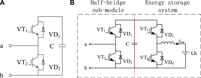
FIGURE 2. CLES-MMC using sub-module topology. (A) shows the SM sub-module topology. (B) shows the ESM sub-module topology.
The SM sub-module is composed of two anti-parallel power switching tubes and a capacitor module C; the ESM sub-module is connected to a bidirectional DC-DC circuit and an energy storage battery Lb on the other side of the capacitor C on the basis of the SM sub-module.
2.2 SM sub-module mechanism analysis
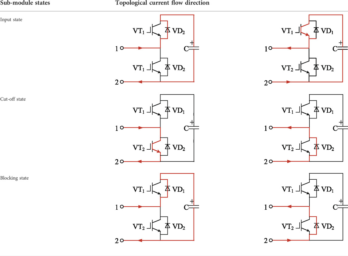
The structure of the SM sub module can be a half-bridge, a full-bridge and a multi-level structure. This paper takes the sub-module of the half-bridge structure as an example to analyze its working principle. As shown in Table 1, there are three working states of the sub-module: the input state, the cut-off state and the blocking state (Jiang et al., 2020).
2.2.1 VT1 is turned on and VT2 is turned off
There are two current flow directions: Flowing clockwise, the current flows in from port 1, charges capacitor C through VD1, and flows out from port 2; flowing anticlockwise, the current flows in from port 2, discharges capacitor C, and flows out from port 1 through VT1. In both states, the capacitor voltage of the sub-module is equal to its port voltage, and it is called the input state.
2.2.2 VT1 is turned off and VT2 is turned on
There are two current flow directions: The current flowing clockwise flows through VT2; the current flowing anticlockwise flows through VD2. When VT1 is turned off and VT2 is turned on, the capacitor is always bypassed regardless of the current directions, so the port voltage is always 0. In this state, the sub-module is out of operation from the MMC system, and it is called the cut-off state.
2.2.3 Both VT1 and VT2 are turned off
There are two current flow directions: when the current is clockwise, it flows through VD1 to charge the sub-module capacitor C; when the current is anticlockwise, it flows through VD2 to bypass the sub-module capacitor C. In this state, the sub-module capacitor can only be charged and cannot be discharged, so this state is usually used for pre-charging the sub-module capacitor before the MMC is officially put into operation.
2.3 ESM sub-module and bidirectional DC-DC mechanism analysis
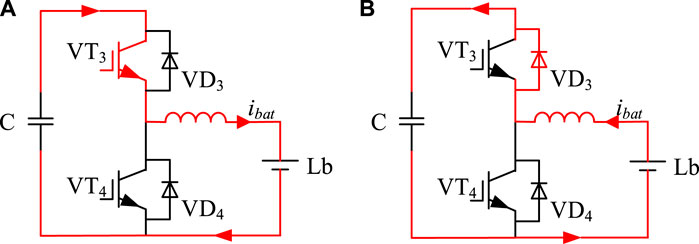
As shown in Figure 2B, the ESM sub-module is composed of the half-bridge sub-module and the energy storage system. Among them, by controlling the switching states of the half-bridge sub-modules VT1 and VT2, the charge and discharge of the capacitor Cm is changed to maintain the stability of the DC voltage of each phase; the energy storage system includes bidirectional DC-DC (Montesinos-Miracle et al., 2013), energy storage filter inductor Lbat and lithium battery (Lb).
As shown in Figure 3, when the bidirectional DC-DC works in the Buck mode, the half-bridge sub-module capacitor charges the Lb. When the bidirectional DC-DC works in the Boost mode, the Lb charges the half-bridge sub-module capacitor. From the above analysis of the bidirectional DC-DC working mode, it can be seen that when the Lb of the energy storage system operates in a low-voltage environment, the charge and discharge current is highly controllable.
Combining the two states of the bidirectional DC-DC circuit and three states of sub-modules in Section 2.2, respectively, a total of six working states of the energy storage sub-module of the MMC-ES can be obtained. That is, by controlling the on-off of the switches of VT3 and VT4, the charging and discharging of the Lb is controlled to stabilize the voltage of the sub-module capacitor, so as to improve the stability of the whole system.
2.4 The relationship between the input of the sub-module and the voltage output
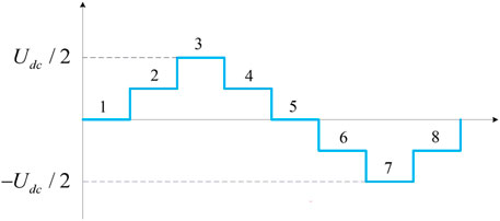
Taking five levels as an example, one power frequency cycle can be divided into eight operating states. Among them, the relationship between the operating state and the number of sub-module input is shown in Table 2. Different from the working mode of the traditional two-level converter, the sub-modules of the upper and lower arms work at the same time when the MMC is working, and the total number of sub-modules put into the upper and lower arms at any time is n. For example, the number of sub-modules put into the MMC phase unit at any time in which the bridge arm is cascaded with four sub-modules is 4, and the sub-modules of the upper bridge arm and the lower bridge arm are put in and cut off according to the complementary rule that is, the number of sub-modules put into the lower bridge arm at a certain time is +1, the number of sub-modules put into the upper bridge arm is −1, and the AC side can output n+1 levels.
Based on Table 2, it can be seen that the output voltage waveform of the AC side of the MMC at 5-level is shown in Figure 4. The eight modes of operation in Table 2 correspond sequentially to the eight voltages in Figure 4.
As shown in Table 3, on the premise of outputting the same waveform, MMC-CLES reduces the use of 22 bidirectional DC-DC circuits and 22 lithium batteries compared with the traditional distributed MMC-ES. Therefore, the topology proposed in this paper has smaller switching losses and higher energy utilization.
The reduction in the number of IGBT in MMC-CLES is mainly reflected in two aspects: One is to achieve a smaller number of submodules than the two topologies by sharing the three-phase DC bus side submodules common. The second is to reduce the number of energy storage components and bidirectional DC-DC systems by adding energy storage systems only to common submodules.
In terms of cost, centralized energy storage MMC is the largest, followed by distributed energy storage MMC, and MMC-CLES is the smallest. In terms of control strategy, MMC is the simplest, distributed energy storage MMC is the most complex, and MMC-CLES is simpler than distributed energy storage MMC.
3 MMC-CLES system modeling
3.1 Differential equation model
You may insert up to five heading levels into your manuscript as can be seen in “Styles” tab of this template. These formatting styles are meant as a guide, as long as the heading levels are clear, Frontiers style will be applied during typesetting.
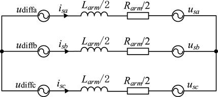
The differential equation modeling of MMC-CLES is derived from the MMC-CLES equivalent circuit established in Figure 5.
Assuming that the DC voltage is Udc, the phase voltage of the AC system is:
where the reference phases of the three phases a, b and c are θa = 0,θb = −2π/3, θc = 2π/3. Usm is the fundamental wave amplitude of the equivalent phase electromotive force of the AC system.
The j-phase AC side current isj and the j-phase upper and lower arm currents ipj and inj satisfy the KCL equation:
The differential mode voltage of the upper and lower bridge arms is defined as udiffj, and the common mode voltage of the upper and lower bridge arms is ucomj. Their expressions are:
3.2 Switching function modeling
When the MMC-CLES is running stably, the capacitor of the energy storage sub-module flows through not only the bridge arm current for energy interaction with AC and DC sides, but also the charge and discharge current of the energy storage system. Taking one phase as an example, the switching function s of the energy storage sub-module is defined as:
Thus, the output voltage expression of a single energy storage sub-module is established:
Where uijk is the output voltage value of the k-th sub-module in the upper or lower bridge arm of a phase; Usmk is the capacitor voltage of the sub-module; sijk is the switching function; iij is the upper or lower arm current of a phase; iLbk is Lb charge and discharge currents of the energy storage system. Among them, i = p (upper bridge arm) or n (lower bridge arm), the number of phases j = a, b, c, k = 1 ∼ n representing the number of sub-modules in the same bridge arm. Therefore, the bridge arm output voltage uij and output current iij can be expressed as:
Ignoring the equivalent impedance of the bridge arm, establish the KVL equation about the upper and lower bridge arms, shown as follows:
Where upj and unj are the upper and lower arm voltages of j-th phase, respectively; Ea is the peak value of the AC voltage; Udc is the DC side voltage.
3.3 Power flow analysis
The internal characteristics of the phase unit and the bridge arm unit are analyzed, and the upper and lower bridge arm voltages are:
Where m is the modulation ratio; Usmk is the capacitor voltage of the energy storage sub-module put into operation in the j-th phase. According to the single-phase equivalent circuit, the KAL equations of the upper and lower bridge arms are established as follows:
Where ipj and inj are the currents flowing through the upper and lower bridge arms respectively; Idc is the DC output current; Ij is the peak value of the phase AC current; φ is the impedance angle. From Eqs 9, 10, the power expressions of the upper and lower arms can be obtained:
The power of the phase unit in Eq. 11 can be simplified to get Eq. 12:
It can be seen from Eq. 12 that the main influences of the MMC-CLES circulation are the fundamental frequency circulation and the double frequency circulation, so the suppression of the circulation should also be focused on these two circulations. The SOC is controlled by controlling the flow of power by controlling the circulating current.
4 New topology control strategy
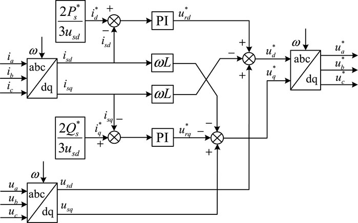
The MMC-ES main control system is shown in Figure 6. First, according to the instantaneous active/reactive power theory, the active/reactive power reference values Ps*, Qs* are transformed to obtain the d and q-axis current reference values id*, iq*; Secondly, three-phase AC currents ia, ib, and ic are separated from active power and reactive power by abc/dq coordinate transformation, and the actual values of the d and q-axis currents isd and isq are obtained; make a difference with the actual value respectively, and obtain the reference value voltages urd* and urq* of axes d and q; in order to accelerate the operation of the system and release the voltage/current coupling effect of axes d and q on the AC side, add a feedforward decoupling. Three-phase AC voltages ua, ub, and uc are transformed by abc/dq to obtain usd and usq; urd*, urq* and the coupling currents of axes d and q jointly complete feedforward decoupling to obtain the ideal values ud*, uq* of the voltages of axes d and q; Finally through the dq/abc inverse coordinate transformation to obtain the three-phase AC voltage modulation waveform.
4.1 Energy storage module control
For the single-phase Buck/Boost DC converter, the double closed-loop control of the voltage outer loop and the current inner loop is adopted. Taking Esm as an example, the Buck mode and the Boost mode are controlled separately. The control diagram is shown in Figure 7, where Usmref is the terminal voltage of the lithium battery; ibat is the current flowing through the lithium battery.

FIGURE 7. Bidirectional DC-DC control system. (A) shows the buck mode control chart. (B) shows the boost mode control chart.
The error between the sub-module capacitor voltage Usm and its reference value Usmref is obtained through the PI controller to obtain the lithium battery charge and discharge current reference value i*bat, and then if multiplied by −1, the circuit will work in the Boost mode. If not multiplied by −1, the circuit will work in the Buck mode, the system modulation wave can be obtained through the current inner loop and charge-discharge compensation. Compared with the triangular carrier, it can generate the corresponding PWM control switching tube VT3 and VT4 to turn on and off to realize the charging and discharging of the lithium battery.
4.2 SOC balance control
The essence of the traditional distributed MMC-ES SOC equalization control is to correct the phase-to-phase power of the three phases and the power of the upper and lower bridge arms and their sub-modules, respectively. MMC-CLES simplifies the SOC control strategy by reducing the number of ESM, it only needs one-level SOC control and sub-module battery SOC balance between the upper and lower bridge arms. In this way, the purpose of fully utilizing the energy storage capacity of the lithium battery is achieved.
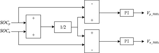
By calculating the average value of the two energy storage lithium batteries of the upper and lower bridge arms as the reference value of SOC, making a difference with the SOC value of the upper and lower bridge arms and passing through two PI controllers to balance the SOC value, and the control diagram is shown in Figure 8. When the system is in a power-starved state, the bidirectional DC-DC circuit is controlled to be in the Boost state, and the upper and lower arms are discharged at the same time. The PI controller is used to suppress the discharge speed of the upper arm battery to achieve the SOC balance effect. When the system is in a power-overflow state, the bidirectional DC-DC circuit is controlled to be in the Buck state, and the upper and lower arm batteries are charged at the same time, and the PI controller is used to suppress the charging speed of the upper arm battery to achieve the SOC balance effect. At the same time, the phase unit power derived from Eq. 12 can be used to achieve the purpose of balancing the SOC by controlling the circulating current (Cheng et al., 2021).
5 Simulation experiment verification
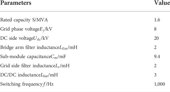
In order to verify the feasibility of the new centralized local energy storage topology based on MMC and the effectiveness of the control strategy proposed and used in this paper, a three-phase five-level MMC-CLES system in the Matlab/Simulink environment is built which operates under the condition of the three-phase unbalance, that is, B and C-phase voltages drop by 50%, and comparative simulation verification is carried out. Table 4 is the simulation parameter table used in this simulation.
The biggest difference in hardware parameters is the size of the energy storage battery and the size of the DC side capacitor, the centralized energy storage topology will be a number of energy storage units in series parallel composition of the energy storage module directly parallel or indirectly paralleled by the DC-DC converter on the DC side of the MMC, the structure is simple and easy to control, but its entire system only uses an energy storage module, because its energy storage module often uses a larger capacity. The distributed energy storage topology uses more small energy storage modules in parallel on the submodules, which solves the problem of poor flexibility of the centralized energy storage topology to a certain extent, but it is difficult to make full use of each energy storage module due to the use of more energy storage modules. It will cause waste of energy storage capacity to a certain extent. The MMC-CLES uses only two energy storage modules to use a smaller battery capacity than centralized and distributed energy storage.
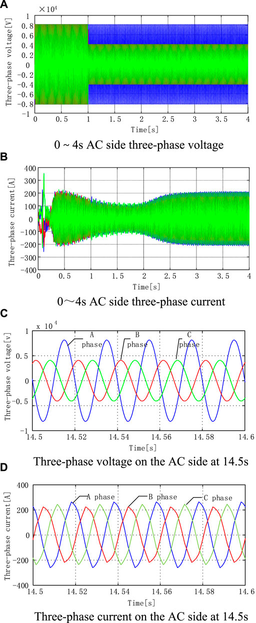
As shown in Figure 9A, the topology proposed in this paper, the A-phase voltage, i.e., the blue line, remains unchanged. B and C-phase voltages, that is, the red and green line, drop by 50% at 1 s, from 8,000 to 4,000 V. As shown in Figure 9B, the waveform of three-phase AC current is 0–4 s, and the voltages of phases B and C drop by 50% at 1 s, because the rapid discharge of the battery of the energy storage system makes up for the power difference of the two-phase drop, so that B and C-phase voltages drop. The phase current reaches the three-phase current steady state again within 0.5 s. It further guarantees the safety and reliability of power grid operation.
Figures 9C,D are the detailed diagrams of the three-phase voltage and current at 14.5–14.6 s, respectively. It can be seen that when the system runs at 14.5 s, the current has basically made up the power difference caused by voltage drop.
As shown in Table 4, the three-phase currents were taken five cycles at 2.5, 5, 7.5, and 10 s for fast Fourier analysis. In this paper, the harmonic content of the fundamental frequency current was not affected on the basis of greatly reducing the switching elements, and its THD content meets the requirements of the national standard.
The rapid balancing of the three-phase current is mainly due to the energy storage system in the topology, which can provide sufficient power support for the AC side. Thanks to the addition of the energy storage system, a better balance effect of current than that of traditional MMC is achieved. According to the calculation formula of the three-phase current unbalance degree: MAX difference phase current ÷ three-phase average current effective value, the three-phase current unbalance of the topology proposed in this paper can be calculated, as shown in Table 5. The analysis is carried out at 2.5, 5, 7.5, and 10 s.
The submodule voltage balancing strategy used in this paper is the NLM sorting algorithm, according to the number of submodules that need to be invested according to the NLM, the submodule with the lowest number of voltages is invested when the bridge arm current charges the submodule capacitor, and the submodule with the highest number of voltages is invested when discharging, thereby suppressing the imbalance between the capacitor voltages.
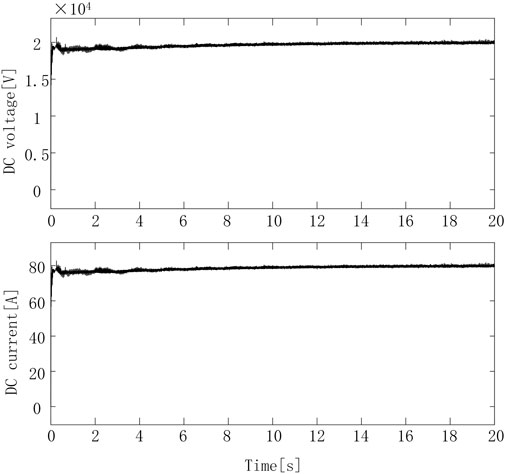
Figure 10 is a waveform diagram of the DC side voltage and current of the converter. It can be seen from the figure that the voltage and current fluctuate slightly when the system starts. When the energy storage system is connected to the converter at 1 s, the system voltage and current tend to be stable after 3 s, the DC voltage is stable at 20,000 V, the DC current is stable at 80 A, and the system runs stably. It can be seen that the topology proposed in this paper has good stability after the battery is connected. The overshoot of the 10 DC voltages and DC currents in Figure 10 is controlled below 5%, and the reason for the steady-state fluctuations is mainly the charge and discharge behavior of the battery.
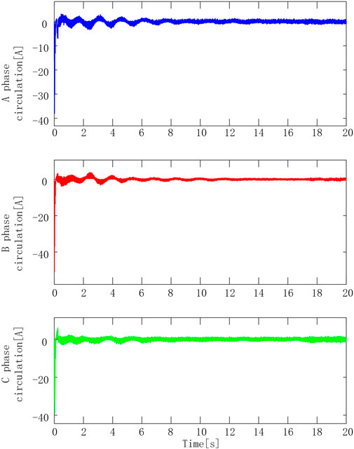
Figure 11 shows the three-phase circulating current of the system. The results show that when the energy storage system does not start to discharge, the three-phase circulating current value is very large. After the energy storage battery begins to discharge at 1 s, the three-phase circulating currents are all reduced to negligible levels. The topology used in this paper can effectively suppress the three-phase circulating current.
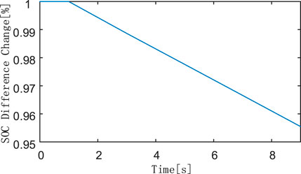
Figure 12 is a fitting curve of the SOC difference change of the two energy storage batteries added to the topology. It can be seen from Table 6 that the two batteries start to discharge synchronously from 1 s to make up for the power shortage on the AC side, and the difference decreased from 1% at 1 s to 0.95549% at 9 s, and the difference fitting curve is a first-order curve, showing a decreasing trend. The effectiveness of the SOC balance control method used in this paper is verified. Table 6 is a change table of the SOC values of two energy storage batteries. The initial value of the battery SOC added to the upper bridge arm energy storage sub-module is set to 50.5%; the initial value of the battery SOC added to the lower bridge arm energy storage sub-module is set to 49.5%. Combining Figure 12 and Table 6, it can be seen that after loading the SOC balance control of the upper and lower arms, the SOC curves of the two batteries are gradually approached by discharging through the bidirectional DC-DC circuit. The purpose of prolonging the service life of the battery is achieved by balancing the utilization rate of the two batteries of the upper and lower bridge arms.
6 Conclusion
This paper proposes a new topology MMC-CLES between the centralized MMC-ES and the distributed MMC-ES, which indirectly reduced the use of power switching tubes and energy storage batteries by reducing the number of sub-modules. The problem of high switching loss and high cost of the energy storage module used in the existing MMC-ES was solved. Through theoretical analysis and simulation verification, it could be seen that MMC-CLES had the following characteristics:
1. The power switching tube and energy storage battery were greatly reduced, which brought about the reduction of cost and switching loss.
2. It had better and faster power difference compensation ability. MMC-CLES could achieve a three-phase current unbalance of 8.16% under three-phase unbalanced conditions.
3. The complemented three-phase current had lower total harmonic distortion. At 14 s, the harmonic content of three-phase current was 3.11%.
The effective operation of MMC-CLES in complex working conditions with low cost and high efficiency verified the prospect of topology in the field of flexible power transmission.
In addition, only the most basic control strategy is selected for SOC and circulating current suppression in this paper, which restrains the topology performance of this paper. Later, based on the MMC-CLES topology, the control method more suitable for this topology will be studied further.
Data availability statement
The original contributions presented in the study are included in the article/supplementary material, further inquiries can be directed to the corresponding author.
Author contributions
Conceptualization, NL; methodology, NL, ZX, and PJ; software, ZX; validation, ZX; resources, NL; data curation, NL, ZA, ZL, and YW; writing—original draft preparation, ZX; writing—review and editing, NL, ZX, and PJ; supervision, ZA, ZL, and YW; funding acquisition, NL. All authors have read and agreed to the published version of the manuscript.
Funding
National Natural Science Foundation of China (52177193); Key Research and Development Program of Shaanxi Province (2022GY-182); China Scholarship Council (CSC) State Scholarship Fund International Clean Energy Talent Project [Grant No. (2018)5046,(2019)157].
Conflict of interest
The authors declare that the research was conducted in the absence of any commercial or financial relationships that could be construed as a potential conflict of interest.
Publisher’s note
All claims expressed in this article are solely those of the authors and do not necessarily represent those of their affiliated organizations, or those of the publisher, the editors and the reviewers. Any product that may be evaluated in this article, or claim that may be made by its manufacturer, is not guaranteed or endorsed by the publisher.
References
Al Haj Hassan, H., Pelov, A., and Nuaymi, L. (2015). Integrating cellular networks, Smart grid, and renewable energy: Analysis, architecture, and challenges. IEEE Access 3, 2755–2770. doi:10.1109/ACCESS.2015.2507781
Baruschka, L., and Mertens, A. (2011). “Comparison of cascaded H-bridge and modular multilevel converters for BESS application[C],” in Energy Conversion Congress and Exposition (ECCE), 909–916.
Chen, Y., Wu, W., Bai, J., Zhang, X., Zongshuai, O., and Fan, Y. (2019). “Coordinated control policy of new energy power system considering demand side characteristics,” in 2019 IEEE 3rd Advanced Information Management, Communicates, Electronic and Automation Control Conference (IMCEC), 1371–1375. doi:10.1109/IMCEC46724.2019.8983834
Cheng, Congzhi, Chen, Xu, Dai, Ke, Huang, Yongshuo, and Pan, Fei (2021). Three-stage balanced control strategy of charge state of MMC-BESS battery[J]. Power Syst. Prot. Control 49 (15), 100–108. doi:10.19783/j.cnki.pspc.201220
Ciccarelli, F., Del Pizzo, A., and Iannuzzi, D. (2013). “An ultra-fast charging architecture based on modular multilevel converters integrated with energy storage buffers[C],” in 2013 8th International Conference and Exhibition on Ecological Vehicles and Renewable Energies (EVER), 1–6.
Coppola, M., Del Pizzo, A., and Iannuzzi, D. (2012). “A power traction converter based on modular multilevel architecture integrated with energy storage devices[C],” in Electrical Systems for Aircraft, Railway and Ship Propulsion (ESARS), 1–7.
Gu, R., Malysz, P., Wang, Deqiang, Wang, Weizhong, Yang, H., and Emadi, A. (2016). “On the design of a direct cell coupled hybrid energy storage system for plug-in hybrid electric vehicles,” in 2016 IEEE Transportation Electrification Conference and Expo (ITEC), Dearborn, MI, USA, 1–7.
Jiang, S., Xin, Y., Li, G., and Wang, L. (2020). A novel DC fault ride-through method for wind farms connected to the grid through bipolar MMC-HVDC transmission. IEEE Trans. Power Deliv. 35 (6), 2937–2950. doi:10.1109/TPWRD.2020.2991722
Karwatzki, D., and Mertens, A. (2018). Generalized control approach for a class of modular multilevel converter topologies. IEEE Trans. Power Electron. 33 (4), 2888–2900. doi:10.1109/tpel.2017.2703917
Lawder, M. T., Suthar, B., Northrop, P. W. C., De, S., Hoff, C. M., Leitermann, O., et al. (2014). Battery energy storage system (BESS) and battery management system (BMS) for grid-scale Applications. Proc. IEEE 102 (6), 1014–1030. doi:10.1109/JPROC.2014.2317451
Li, J. L., Yuan, X. D., Yu, Z. G., and Ge, L. (2019). A review of research on using energy storage systems to improve power quality of power grids. Automation Electr. Power Syst. 43 (08), 15–24.
Liang, G., Tafti, H. D., Farivar, G. G., Pou, J., Townsend, C. D., Konstantinou, G., et al. (2021). Analytical derivation of intersubmodule active power disparity limits in modular multilevel converter-based battery energy storage systems. IEEE Trans. Power Electron. 36 (3), 2864–2874. doi:10.1109/tpel.2020.3014739
Montesinos-Miracle, D., Massot-Campos, M., Bergas-Jane, J., Galceran-Arellano, S., and Rufer, A. (2013). Design and control of a modular multilevel DC/DC converter for regenerative applications. IEEE Trans. Power Electron. 28 (08), 3970–3979. doi:10.1109/tpel.2012.2231702
Perez, M. A., Bernet, S., Rodriguez, J., Kouro, S., and Lizana, R. (2015). Circuit topologies, modeling, control schemes, and applications of modular multilevel converters. IEEE Trans. Power Electron. 30 (1), 4–17. doi:10.1109/TPEL.2014.2310127
Schroeder, M., Henninger, S., Jaeger, J., Ras, A., Rubenbauer, H., and Leu, H. (2013). “Integration of batteries into a modular multilevel converter[C],” in 2013 15th European Conference on Power Electronics andApplications (EPE), 2–6.
Soong, T., and Lehn, P. W. (2014). Evaluation of emerging modular multilevel converters for BESS applications. IEEE Trans. Power Deliv. 29 (5), 2086–2094. doi:10.1109/tpwrd.2014.2341181
Trintis, I., Munk-Nielsen, S., and Teodorescu, R. (2011). A new modular multilevel converter with integrated energy storage[C]//IECON 2011 - 37th Annual Conference on. IEEE Ind. Electron. Soc. 7 (10), 1075–1080.
Vasiladiotis, M., and Rufer, A. (2015). Analysis and control of modular multilevel converters with integrated battery energy storage. IEEE Trans. Power Electron. 30 (1), 163–175. doi:10.1109/tpel.2014.2303297
Wang, D., Tian, J., Mao, C., Lu, J., Duan, Y., Qiu, J., et al. (2016). A 10-kV/400-V 500-kVA electronic power transformer. IEEE Trans. Ind. Electron. 63 (11), 6653–6663. doi:10.1109/tie.2016.2586440
Zhang, Wenliang, Qiu, Ming, and Lai, Xiaokang (2008). Application of energy storage technologies in power grids[J]. Power Syst. Technol. 32 (7), 1–9.
Keywords: energy storage MMC, MMC-CLES, SOC, three-phase unbalance degree, THD
Citation: Li N, Xiao Z, Jiang P, An Z, Li Z and Wang Y (2022) A centralized local energy storage modular multilevel converter. Front. Energy Res. 10:1018721. doi: 10.3389/fenrg.2022.1018721
Received: 13 August 2022; Accepted: 01 September 2022;
Published: 23 September 2022.
Edited by:
Xiaokang Liu, Politecnico di Milano, ItalyReviewed by:
Hao Zhong, China Three Gorges University, ChinaShuzheng Wang, Nanjing Institute of Technology (NJIT), China
Dongbo Guo, Northeast Electric Power University, China
Copyright © 2022 Li, Xiao, Jiang, An, Li and Wang. This is an open-access article distributed under the terms of the Creative Commons Attribution License (CC BY). The use, distribution or reproduction in other forums is permitted, provided the original author(s) and the copyright owner(s) are credited and that the original publication in this journal is cited, in accordance with accepted academic practice. No use, distribution or reproduction is permitted which does not comply with these terms.
*Correspondence: Ning Li, bGluaW5nODNAeGF1dC5lZHUuY24=
 Ning Li
 Zihan Xiao
