 Qingshen Xu
 Jie Lou1*
- 1School of Electrical Engineering, Shandong University, Jinan, China
- 2State Grid Jinan Power Supply Company, Jinan, China
- 3State Grid Binzhou Power Supply Company, Jinan, China
In addition to the traditional long-distance and bulk power transmission application, the HVDC system can bring additional benefits to the system by providing ancillary service. The high-voltage direct-current transmission (HVDC) system can regulate its power flow in a very short time and can be used to provide emergency support to rescue the disturbed system from very bad conditions. However, because traditional generators cannot meet the great power demand of the HVDC system in a short time, the fast response of the HVDC system may cause severe power-unbalance events in the power supporting system. In this paper, a combination frequency response control (CFRC) is proposed for the fast frequency response (FFR) and HVDC system coordinating under the contingency. With the proposed combination frequency response control, the most use of the frequency response capacity of the HVDC system could be made. Meanwhile, the coordination between the HVDC system and fast frequency response could prevent the frequency of the power-source-provided system from dropping to an unacceptable level. The simulation study is conducted on a highly reduced power system model of the three North American interconnections. The simulation verification shows the effectiveness and feasibility of the proposed combination frequency response control and indicates that the frequency stability for both side systems of the HVDC system could be significantly improved with the proposed combination frequency response control. In the future, the communication delay between energy storage and HVDC will be considered in the strategy to further improve the accuracy of fast frequency response.
1 Introduction
Over the past decade, high-voltage direct-current transmission (HVDC) systems have witnessed continuous increases around the world with the development of advancing power electronic technology (Sun et al., 2021a; Xiao et al., 2021; Sun et al., 2022a). In Asia, China, which has the greatest number of HVDC operating and planning systems, has continuously led the global HVDC system construction in recent years (Li et al., 2019). In the United States, HVDC transmission technology has been widely accepted as a good choice to achieve economic long-distance and bulk power transmission and to interconnect all three interconnections independently (Sun et al., 2019a).
With the advancement of voltage source converter (VSC) technology, the applications of the HVDC system have been greatly improved (Sun et al., 2017; Sun et al., 2019b). In addition to the long distance and bulk power delivery, the HVDC system could provide a quick dynamic response to different types of system disturbances. Sharing the frequency response reserves via the HVDC system is a high-value product. Over the past decade, some projects and researchers have considered including HVDC systems in frequency control. MISO (2014) adopted the VSC-HVDC system to share the frequency response reserve that could bring 25% financial benefits to the system operator, which justifies the economy of the HVDC transmission system. In 2017, the Interconnection Seam Study project was cooperatively investigated by the Department of Energy (DOE) and research partners, including national laboratories and universities. In this project, sharing the frequency response reserve was one of the critical benefits that could bring a major contribution to the operating financial benefits of the HVDC system (NREL). The Pacific Northwest National Laboratory also studied the possibility of the frequency response serviced from multi-terminal HVDC networks in the American grid (Elizondo and Kirkham, 2016).
Different from the traditional synchronous generators in the electric power grid, the active power control of the HVDC system is decoupled from the frequency (Sun et al., 2020). Thus, the HVDC system could realize a quick frequency response to the disturbed system under the contingency. In practice, the power regulation of the HVDC system under an event can be up to hundreds of MW per second, which could significantly improve the frequency of nadir during the event (Belkin, 2012). However, the typical large fossil-fired thermal generator could only ramp 1% of its capacity in 1 min (Kirby). Due to the response rate deviation, the unrestricted power regulation rate of the HVDC system may cause huge frequency oscillations in the supporting system and even cause power outages. Therefore, improving the system frequency response performance through the HVDC system or guaranteeing the operating safety of the support-provided system is a clear dilemma in system frequency control.
Due to the great need for frequency regulation and the consequent economic advantage, numerous fast frequency response (FFR) resources represented by energy storage equipment, such as batteries and flywheels, have been recently installed into the system (Kim et al., 2017). The FFRs have very high cycle stability, high power density, and fast charging and discharging owing to low inner resistance (Zhao et al., 2015). Under the frequency event, the FFRs could provide a quick response to the system, which could digest part of the influence caused by the HVDC system frequency control.
The coordination operation of the HVDC system and energy storage has been recently investigated in some papers mainly focusing on renewable energy integration improvement (Junyent-Ferr et al., 2015; Xu et al., 2019; Sun et al., 2022b) and HVDC system operation enhancement (Yang et al., 2019; Sun et al., 2021b; Sun et al., 2021c; Judge and Green, 2019). Some papers have also discussed the effect of energy storage on HVDC system frequency control (Ray et al., 2009; Rakhshani et al., 2017; Pathak et al., 2017; Yang et al., 2019; Judge and Green, 2019). However, most of the research aims to use energy storage to assist the HVDC system frequency control for performance improvement. Considering energy storage as FFRs to coordinate the HVDC system frequency response for both sides of system operating safety has not received much attention.
In the past, the communication and real-time situational awareness of the devices in the system could not satisfy the fast frequency response requirement. Thanks to the advancement of the wide-area monitoring system, the device information interaction is fast enough and more reliable to enable the HVDC system and FFRs coordination control (You et al., 2016; Zhou et al., 2016). In this paper, a combination frequency response control (CFRC) strategy is developed for the FFRs and HVDC system coordinating under the contingency. The proposed combination control is based on the active power control of the HVDC system and FFRs, as well as real-time communication. With the proposed combination frequency response control, the most use of the frequency response capacity of the HVDC system could be made. Meanwhile, the coordination between the HVDC system and FFRs could also prevent the frequency of the power-source-provided system from dropping to an unacceptable level.
This paper is organized as follows: Section 2 introduces the studied system model. Section 3 introduces the motivation of this paper and the transient stability analysis of the system with FFRs and HVDC system integration. The operation principle and control strategy of the proposed combination frequency response control are described in Section 4. The simulation verifications are presented based on a highly reduced power system model of the three North American interconnections in Section 5. Finally, the results and conclusion are discussed in Section 6.
2 Model description
In this paper, a two-terminal VSC-HVDC system interconnecting two asynchronous grids is depicted in Figure 1. The traditional fossil-fired thermal generator is adopted, and the battery energy storage system (BESS) is used as FFR.
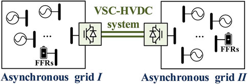
FIGURE 1. Configuration of the two-terminal VSC-HVDC system interconnecting two asynchronous grids.
The half-bridge VSC is adopted as the converter of the HVDC system; the equivalent circuit of one VSC of the VSC-HVDC system connected to an asynchronous AC grid is depicted in Figure 2.
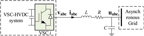
FIGURE 2. Diagram of a VSC in the VSC-HVDC system, where uabc represents the AC voltage of the asynchronous grid, vabc and iabc are the output AC voltage and AC current of the VSC-HVDC system, and R and L denote the resistance and inductance of the interfacing reactor, respectively.
As shown in Figure 2, the VSC mathematical model can be rewritten according to Xiao et al. (2015):
For the inner current control loop of VSC, the synchronous dq-frame is adopted for the current controller implementation. The synchronous dq-axis voltage and current components are transformed with Park transformation from balanced static abc-axis voltages and currents. Thus, the VSC dynamic equations in the synchronous dq-frame could be expressed as
where ω represents the angular frequency of the AC grid. Based on Eq. 2, the inner current control loop of the VSC could be expressed as
where kp and ki are the proportional and integral gains.
The basic control of the VSC is shown in Figure 3, where CAPC is the constant active power control, CDVC is the constant DC voltage control, CRPC is the constant reactive power control, and CFRC is a combination frequency response control.
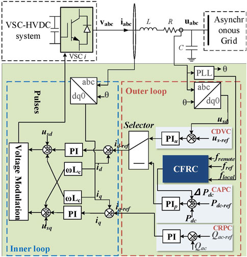
FIGURE 3. Basic control of the VSC-HVDC system (one terminal).
3 Problem description
3.1 Motivation
In addition to the long-distance and bulk power transmission, the advancement of the HVDC transmission technology brings more benefits to the power system, such as large-scale renewable integration and ancillary services. In some severe events, the HVDC could provide bulk power support to the disturbed system in a very short time, which could significantly suppress the influence of the disturbance and rescue the disturbed system from further deterioration or even outage. However, traditional generators cannot meet the great power demand of the HVDC system in a short time. The fast response of the HVDC system may cause severe power-unbalance events in the power supporting system. In order to avoid this issue, a compromise has to be made that limits the HVDC’s fast response capability by setting operating constraints. However, with the increasing integration of large-scale renewable energy into the electric system, it is harder to meet the real-time power balance due to its random output. The fast controllability of the HVDC system should receive attention and needs a better coordination scheme for releasing its support capability to meet the growing demand for renewable energy output regulation.
The use of FFR motivates a prospective solution for the aforementioned problem such that the fast response capacity of the HVDC system could be best used. As shown in the following section, the participation of the local FFRs could prevent the power-sourced-provided grid from falling into unstable operating conditions, which enables the reaction of HVDC at a fast pace other than being limited. This paper does not claim by any means that the coordination control between the HVDC system and FFRs will bring more financially attractive benefits than single HVDC system control or FFRs response.
3.2 Transient stability analysis of the system with FFRs and HVDC system integration
This section shows that the use of FFR is beneficial to avoiding system instability when utilizing the fast controllability of the HVDC to support system frequency by using the extended equal-area criterion (EEAC) theory.
The EEAC theory is proposed by Professor Yusheng Xue as an effective method in the quantitative analysis of power system transient stability (Liao and Yun, 2004). The outstanding performances of EEAC have been demonstrated by online operation records in many energy management system (EMS) environments worldwide (Xu et al., 2017). If the power system is subject to a large disturbance (line break, short circuit, machine cut, load cut, etc.), the power system will be transiently stable under this large disturbance if the individual generating units can maintain synchronous operation and have acceptable voltage and frequency levels. The EEAC theory assumes that all generators in the system can be divided into two generator clusters under disturbance. Intuitively speaking, the generators being heavily disturbed are grouped and referred to as the critical cluster, whereas the rest are grouped as the remaining cluster.
When energy storage equipment and HVDC are connected to the power system, additional electromagnetic damping torque is generated on the generator side, which suppresses the oscillatory instability of the power angle. Analyzed in terms of the extended equal area method, FFR and HVDC deliver electromagnetic power to the power system, providing additional damping area and thus improving the transient stability of the system. Assuming that such two clusters have been found and the HVDC system and FFRs are included in the critical cluster, the whole system can be treated as a time-varying two-machine system. The equivalent inertia could be expressed as
where c represents the critical generator cluster and r represents the remaining cluster. Mc and Mr are the equivalent inertia of the critical generator cluster and the remaining cluster, respectively. Pmc and Pmr are the equivalent mechanical power of the critical generator cluster and the remaining cluster, respectively. Pec and Per are the equivalent electrical power of the critical generator cluster and the remaining cluster, respectively. δc and δr are the generator rotor angles.
With the standard simplifying assumptions, the motion of a system could be described as
Here, M, Pm, and Pe can be described as
where M and Mtotal are equivalent inertia and total inertia of the system, respectively. Pm is the equivalent mechanical power and Pe is the equivalent electromagnetic power of the system.
As shown in Eq. 5, the stability problem of the system can be equivalent to the stability of the relative generator rotor angle:
Equation 5 can be converted to
When the HVDC system extracts the power from the supporting system to realize power support, Pec is changed to
where ∆PES is the injection power from FFRs to the power-sourced-provided system and ∆Pdc is the extracting power from the power-sourced-provided system to the HVDC system, which could be expressed as
where RES and RHVDC are the response rates of FFRs and the HVDC system.
The relative generator rotor angle could be expressed as
where Pec’ is the equivalent electrical power of the system after HVDC system support and δs’ is the relative generator rotor angle after HVDC system support.
The stability margin of the system’s first swing changes to
where δ0 is the operating point of the equivalent generation before the HVDC system support, δDSP is the dynamic saddle point, η’ is the stability margin of the system’s first swing after HVDC system support, and Pe’ is the equivalent electromagnetic power of system after HVDC system support.
The stability margin deviation of the system’s first swing can be depicted as
As shown in Eq. 14, if RES(t) − RHVDC(t) > 0, the stability margin deviation is large than 0 so that the system stability will not be affected by the frequency support of the HVDC system. If RES(t) − RHVDC(t) < 0, the stability margin deviation is small than 0, so the system stability will be influenced by the HVDC system support. In order to demonstrate the impact of the HVDC system support and FFR coordination of the system transient stability, groups of frequency curves with different ratios k between RES(t) and RHVDC(t) are depicted in Figure 4. The ratio k is defined as k = RES(t)/RHVDC(t).
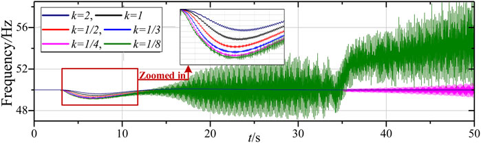
FIGURE 4. Frequency response curves with different ratios.
Figure 4 shows that the response rate ratios between FFRs and the HVDC system significantly affect the transient stability of the power-sourced-provided grid. Figure 4 also shows that the faster response rate of FFRs could overcome the negative effect of the HVDC system on the supporting system stability during frequency support. Compared to traditional no FFR response, FFRs and the HVDC system coordination could support the system frequency without harming the system stability. Therefore, the coordination control of the HVDC system and FFRs is preferred during frequency support.
4 Combination frequency response control
Due to the increasing penetration of renewable energy and energy storage in the grid, the demand for real-time interactive source-load-storage response has increased significantly. Recently, FFR devices, represented by energy storage, have gradually started to be deployed as auxiliary services in the system. FFR can provide a fast power response to the measured or observed changes in system frequency, thus significantly mitigating power fluctuations due to the high proportion of renewable energy injected into the power system.
In addition, voltage source converter-based high-voltage DC (VSC-HVDC) is a flexible DC transmission technology with fast power reversal capability. The active and reactive power can be controlled independently. It has many advantages, such as a black start and the ability to connect to weak AC networks, which can increase the flexibility of interconnected grids to support each other and regional standby complementarity. Owing to the voltage source converter-based characteristic, the FFRs could provide the same response rate output as the HVDC system. Thus, the frequency response control of the HVDC system should consider the capacity of the FFRs for the operating stability of the power-sourced-provided grid. This paper proposes a combination frequency response control (CFRC) strategy for FFRs and the HVDC system coordinating under the contingency. The detailed control strategy of the CFRC is introduced in the following sections.
4.1 General energy management system structure of the system integrating the HVDC system and FFRs
The realization coordination control of the HVDC system and FFRs needs a reliable real-time energy management system (EMS). Figure 5 shows the general EMS structure of the system integrating the HVDC system and FFRs to guarantee the operation of the proposed CFRC. As shown in Figure 5, the EMS is based on the wide-area monitoring system, and FFRs and the HVDC system information interaction could be achieved speedily and reliably. The PMU in the wide-area measurement system measures the frequency and phase angle quantities on the contact line associated with the FFR and then packages the data to send to the FFRs EMS. The EMS of the FFRs continuously monitors the operating condition of the FFRs, converts the FFRs’ operation condition to the operating constraints, and then sends it to CFRC. After that, the operating constraints of the FFRs are sent to the CFRC for further analysis, and the response function of the HVDC system is determined if a frequency event occurs.
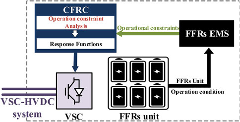
FIGURE 5. EMS structure of the system integrating the HVDC system and FFRs.
4.2 Combination frequency response control
The objective of the CFRC is to realize a reasonable HVDC frequency response control that makes the most of the fast response capacity of the HVDC system while guaranteeing the power-sourced-provided grid operating safety. Therefore, the CFRC is separated into two parts: one for HVDC emergency support control and the other for frequency stabilization identification control. The HVDC emergency support control is designed to quickly stabilize the system frequency and reduce system frequency variations after the occurrence of a disturbance. Then, the frequency stabilization identification ensures that the HVDC emergency support control is over. The CFRC is configured on one of the terminals of the VSC-HVDC system and works on constant active power control. The basic control diagram of the CFRC is depicted in Figure 6.
(1) HVDC emergency support control aims to reduce the amount of frequency change after an AC system incident. In conventional converter stations, HVDC frequency control mostly uses a fixed proportionality factor without considering the frequency regulation capability of the AC grid on the opposite side involved in frequency regulation. This leads to the possibility of large deviations in the frequency of the AC grid on the opposite side during the use of HVDC support power, affecting its own safe and stable operation. In order to overcome this problem, this paper adopts the amount of frequency deviation on both sides as the control quantity.

FIGURE 6. Basic control diagram of the CFRC.
Figure 7 depicts the flowchart of the HVDC emergency support control. In Figure 7, flocal is the measured frequency of the PCC bus, fremote is the measured frequency on the PCC bus of the other terminal of the VSC-HVDC system, fref is the nominal frequency, fdeadband is the dead-band of the CFRC activation, and kHV+FFR and kHV are the droop coefficients for the HVDC system frequency response under different operation conditions, respectively. The active-frequency regulation slopes kp and ki are determined by considering the online reserve capacity and inertia of the AC grid on both sides of the HVDC.
(2) The frequency stability identification control aims to determine the end moment of the HVDC emergency support control. Therefore, the current amount of power on the HVDC is automatically maintained after the system frequency has stabilized. The judgment criterion is shown as follows:
where FFRop-cap, FFRcap, and λ are the operating capacities of the FFRs, the total capacity of FFRs, and the buffering coefficient for FFRs exiting, respectively.
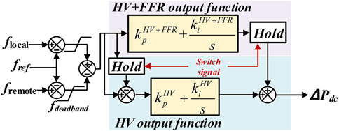
FIGURE 7. Flowchart of the HVDC emergency support control.
As shown in Figure 6, the controller determines the frequency fluctuation condition of the system by monitoring the power of the AC system to which the DC station is connected. When the operating capacity is less than the capacity threshold, the controller sends a signal to keep the current amount of power on the HVDC stable. The frequency stability identification control ensures that the system is stable by identifying the system capacity before exiting the combined frequency response control.
(3) The CFRC process is described as follows: when a frequency event occurs at one connected grid and the frequency oscillation is over the dead band, the CFRC is activated to respond to the frequency oscillation. In order to suppress the influence of the HVDC system on the power-sourced-provided grid, FFRs in the power-sourced-provided grid are activated at the same time. FFRs provide support with the same response rate as the HVDC system. Meanwhile, its EMS continuously monitors the capacity condition of the FFR unit. When the capacity of the FFR unit reaches Eq. 15, FFRs exit the support process and send a signal to the CFRC. Once the CFRC receives the signal from FFRs, the CFRC will use the “hold” function to freeze the value of the current frequency change and the HV+FFR output function. Because the value of the current frequency change is frozen by the “hold” function, the HV output function is automatically activated and the CFRC will provide support to the disturbed grid with kHV until the frequency at the disturbed grid is stable.
With the proposed CFRC, the HVDC system could provide a fast enough response to the disturbed system to improve the frequency nadir and stabilize the frequency as soon as possible. Meanwhile, with the continuous monitoring of the capacity condition of the FFRs, the CFRC could adjust the response rate of the HVDC system to prevent the power-sourced-provided grid from falling into a bad operating condition.
5 Simulation verification
5.1 Model description
To verify the performance of the proposed CFRC, a highly reduced North American grid (NAG) model is adopted in PSCAD/EMTDC, as depicted in Figure 8. The highly reduced models are developed from an equivalent NAG model. The data of this NAG model have been openly published (CURENT, 1001; Geni). The equivalent NAG model has been validated by a full NAG model in power flow and frequency response perspective. Because the equivalent NAG model is too big for the PSCAD simulation, the EI and WECC systems are further reduced with the generation aggregation method, in which the EI system is represented by seven dynamic cluster generations and the WECC system is represented by six dynamic cluster generations. The data of these two systems are shown in Table 1. FFRs configured in the WECC and EI are assumed as VSC-based energy storage, and the capacity is assumed as 10 MWh/800 MW. A two-terminal VSC-HVDC system is embedded in highly reduced models, where the VSC1 is connected to WECC and the VSC2 is connected to EI. The VSC1 works at CAPC with CPFC, and the VSC2 works at CDVC. The frequency dead-band of the CPFC is set as .05 Hz, and the kHV+FFR and kPHV of the CPFC are set to 5 and 3, respectively. The parameters of the VSC-HVDC system are depicted in Table 2. The parameters of the electrochemical energy storage are depicted in Table 3 (Meng et al., 2020). The initial condition of the VSC-HVDC system is 1,200 MW, and the direction is from WECC to EI.
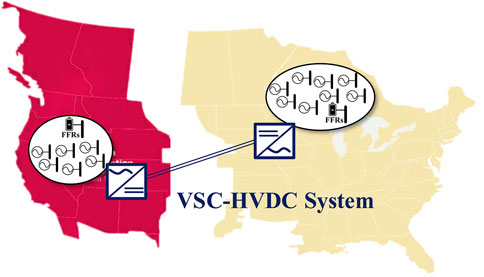
FIGURE 8. Configuration of the NAG system.
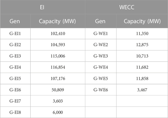
TABLE 1. Generation capacities of the highly NAG model.
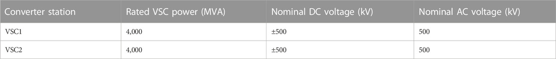
TABLE 2. Converters’ parameters in the VSC-HVDC system.
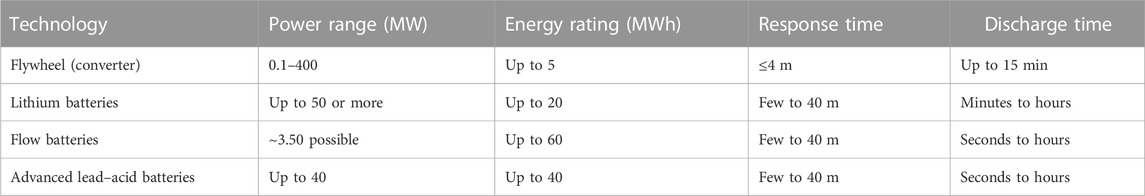
TABLE 3. Examples of the electrochemical energy storage suitable for fast response services.
5.2 Case I: Trip one generator in EI (the response of FFRs does not exceed their capacity)
At t = 3 s, the generator G-EI7 (3,603 MW) is tripped in EI. Figure 9 shows the simulation results of the VSC-HVDC system using the CFRC to support the EI system.
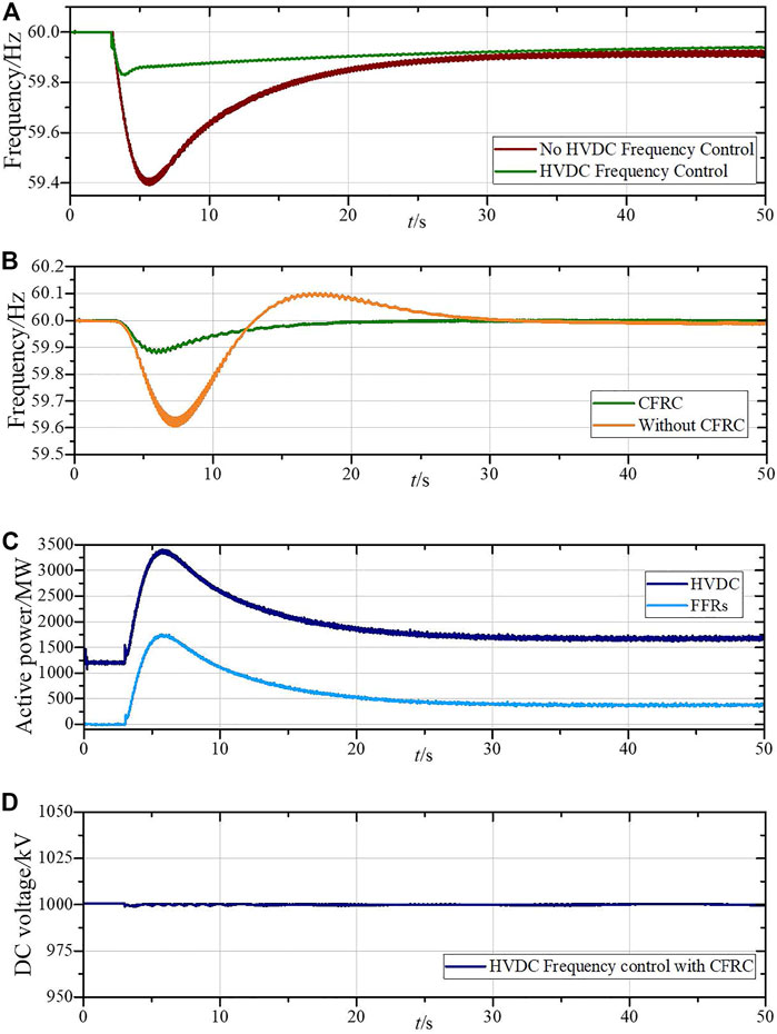
FIGURE 9. Simulation results of the VSC-HVDC system in frequency control. (A) Frequency of the EI with HVDC frequency control and without HVDC frequency control. (B) Frequency of the WECC with and without CFRC. (C) Power flow on the VSC-HVDC system and the output of FFRs. (D) DC voltage of the VSC-HVDC system during the HVDC frequency control with the CFRC.
As shown in Figure 9A, if the disturbed system only relies on its inner frequency response capacity, the frequency will drop to 59.6 Hz, which may activate the automatic under-frequency load shedding and lead to serious financial loss for the system operator and power customers. However, with the HVDC frequency control, the frequency nadir of the disturbed system can be significantly improved. It reduces the probability of serious events. However, owing to the fast response performance of the HVDC system, the frequency of the power-source-provided system will be affected.
As shown in Figure 9B, the frequency in the power-source-provided system drops to 59.6 Hz. It is not an acceptable operating frequency for the system’s inner devices. With the proposed CFRC, the frequency drop in the power-source-provided system is suppressed, and the equipment in the power-source-provided system could operate well under this frequency until the contingency is clear.
Figure 9C shows the power flow change of the HVDC system and the power output change of FFRs. Figure 9D shows the DC voltage change of the HVDC system. As shown in Figures 9C, D, with the proposed CPFC, the FFRs could follow the HVDC system frequency response in real-time to mitigate the influence caused by the HVDC system frequency response to the power-source-provided system so that avoiding unacceptable frequency drops. The DC voltage during the CPFC working process is stable, which indicates that the CPFC will not influence the stability of the VSC-HVDC system’s normal operation.
5.3 Case II: Trip one generator in EI (the response of FFRs exceeds their capacity)
At t = 3 s, the generator G-EI8 (6,000 MW) is tripped in EI. At t = 10 s, due to out-of-capacity, FFRs exit from the coordination control. Figure 10 shows the simulation results of the VSC-HVDC system using the CFRC to support the EI system.
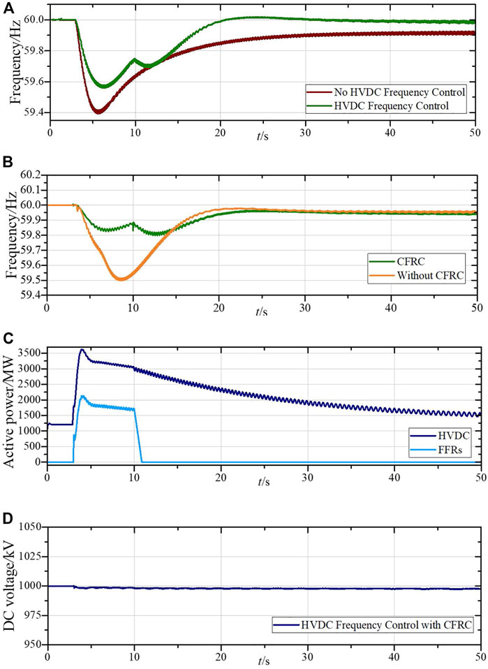
FIGURE 10. Simulation results of the VSC-HVDC system in frequency control. (A) Frequency of the EI with HVDC frequency control and without HVDC frequency control. (B) Frequency of the WECC with and without CFRC. (C) Power flow on the VSC-HVDC system and the output of FFRs. (D) DC voltage during the HVDC frequency control with the CFRC.
As shown in Figure 10, after the generator trips in the EI, the HVDC system immediately responds to the frequency variation. With the CFPC, FFRs follow the HVDC system power flow change to suppress the frequency deviation in the power-source-provided system. At t = 10 s, FFRs exit from the support for out-of-capacity. As shown in Figure 10C, the output of FFRs drops to 0 MW with a constant ramping rate. According to the proposed CPFC, the output function of the HVDC system changes from the HV+FFR output function to the HV output function. As shown in Figure 10C, the response rate of the HVDC is decreased. During the function switch process, the frequency in the WECC (Figure 10B) and EI (Figure 10A) has acceptable oscillation. Figure 10D shows that the DC voltage is also stable during the CPFC working process. The simulation results indicate that the proposed CPFC could enhance the frequency response capacity of the HVDC system while avoiding unacceptable frequency variation of the power-source-provided system under the contingency.
6 Conclusion
The HVDC system could provide a quick dynamic response to various system disturbances. Providing ancillary services through the HVDC system is expected to be a high-value product for system operation. However, due to the response rate deviation between the traditional generators and the HVDC system, the unrestricted power regulation rate of the HVDC system may cause huge frequency oscillations in the supporting system and even cause power outages. Therefore, improving the system frequency response performance through the HVDC system or guaranteeing the operating safety of the support-provided system is a clear dilemma in system frequency control. In this paper, based on the coordination between the HVDC system and fast frequency response, a combination frequency response control is proposed to make the most use of the fast response capacity of the HVDC system and prevent the power-sourced-provided grid from falling into unstable operating conditions. The proposed combination frequency response control is demonstrated based on a highly reduced power system model of the three North American interconnections. The results from the simulation show that the proposed combination frequency response control is effective and performs well under different contingencies. With the proposed combination frequency response control, the frequency stability of the disturbed system could be significantly improved. Meanwhile, the frequency of the power-source-provided system will be kept within an acceptable level for the system’s normal operation. In the future, the communication delay between energy storage and HVDC will be considered in the strategy to further improve the accuracy of fast frequency response.
Data availability statement
The original contributions presented in the study are included in the article. The data cannot be fully given because of NDA restrictions. Further inquiries can be directed to the corresponding author.
Author contributions
QX wrote a section of the manuscript. JL, DN, and PL contributed to data curation, analysis, and visualization. JL contributed to the manuscript revision. All authors approved the submitted version.
Conflict of interest
DN was employed by State Grid Jinan Power Supply Company. PL was employed by State Grid Binzhou Power Supply Company.
The remaining authors declare that the research was conducted in the absence of any commercial or financial relationships that could be construed as a potential conflict of interest.
Publisher’s note
All claims expressed in this article are solely those of the authors and do not necessarily represent those of their affiliated organizations or those of the publisher, the editors, and the reviewers. Any product that may be evaluated in this article, or claim that may be made by its manufacturer, is not guaranteed or endorsed by the publisher.
References
Belkin, P. (2012). HVDC and power electronic systems for overhead line and insulated cable applications. Paris, France: CIGRE San Francisco Colloquium.
Curent, CURENT North American grid. Available: https://db.bettergrids.org/bettergrids/handle/1001/414.
Elizondo, M. A., and Kirkham, H. (2016). Economics of high voltage dc networks. USA: Pacific Northwest National Laboratory.
Geni Map. Map of United States of America electricity grid. Available at: https://www.geni.org/globalenergy/library/national_energy_grid/united-states-of-america/americannationalelectricitygrid.shtml.
Judge, P. D., and Green, T. C. (2019). Modular multilevel converter with partially rated integrated energy storage suitable for frequency support and ancillary service provision. IEEE Trans. Power Del. 34 (1), 208–219. doi:10.1109/tpwrd.2018.2874209
Junyent-Ferr, A., Pipelzadeh, Y., and Green, T. C. (2015). Blending HVDC-link energy storage and offshore wind turbine inertia for fast frequency response. IEEE Trans. Sustain. Energy 6 (3), 1059–1066. doi:10.1109/tste.2014.2360147
Kim, Y., Del-Rosario-Calaf, G., and Norford, L. K. (2017). Analysis and experimental implementation of grid frequency regulation using behind-the-meter batteries compensating for fast load demand variations. IEEE Trans. Power Syst. 32 (1), 484–498. doi:10.1109/tpwrs.2016.2561258
Kirby, B. A method and case study capability of a control area or balancing authority and implications for moderate or high wind penetration. Available: https://www.nrel.gov/docs/fy05osti/38153.pdf.
Li, J., Zuo, X., Zhao, Y., Lv, X., and Wang, J. (2019). Operation, analysis and experiments of DC transformers based on modular multilevel converters for HVDC applications. CSEE J. Power Energy Syst. 5 (1), 87–99. doi:10.17775/cseejpes.2017.00630
Liao, H., and Yun, T. (2004). Qualitative analysis of the CCEBC/EEAC method. Sci. China Ser. E Technol. Sci. 47.
Meng, L., Zafar, J., Khadem, S. K., Collinson, A., Murchie, K. C., Coffele, F., et al. (2020). Fast frequency response from energy storage systems—a review of grid standards, projects and technical issues. IEEE Trans. Smart Grid 11 (2), 1566–1581. doi:10.1109/TSG.2019.2940173
Nrel, Interconnections seam study. Available: https://www.nrel.gov/analysis/seams.html.
Pathak, N., Verma, A., and Bhatti, T. S. “Utilizing HVDC links as a energy storing device in AGC operation of hydro-thermal-gas based interconnected power systems,” in Proceedings of the 2017 International Conference on Technological Advancements in Power and Energy (TAP Energy), Kollam, India, December 2017.
Rakhshani, E., Mehrjerdi, H., Al-Emadi, N. A., and Rouzbehi, K. “On sizing the required energy of HVDC based inertia emulation for frequency control,” in Proceedings of the 2017 IEEE Power & Energy Society General Meeting, Chicago, IL, USA, July 2017.
Ray, P. K., Mohanty, S. R., Kishor, N., and Mohanty, A. “Small-signal analysis of hybrid distributed generation system with HVDC-link and energy storage elements,” in Proceedings of the 2009 Second International Conference on Emerging Trends in Engineering & Technology, Nagpur, India, December 2009.
Sun, J., Li, M., Zhang, Z., Xu, T., He, J., Wang, H., et al. (2017). Renewable energy transmission by HVDC across the continent: System challenges and opportunities. CSEE J. Power Energy Syst. 3 (4), 353–364. doi:10.17775/cseejpes.2017.01200
Sun, K., Li, K. J., Zhang, Z., Liang, Y., Liu, Z., and Lee, W. J. (2022). An integration scheme of renewable energies, hydrogen plant, and logistics center in the suburban power grid. IEEE Trans. Ind. Appl. 58 (2), 2771–2779. doi:10.1109/tia.2021.3111842
Sun, K., Li, K. J., Lee, W. J., Wang, Z. D., Bao, W., Liu, Z., et al. (2019). VSC-MTDC system integrating offshore wind farms based optimal distribution method for financial improvement on wind producers. IEEE Trans. Ind. Appl. 55 (3), 2232–2240. doi:10.1109/tia.2019.2897672
Sun, K., Qiu, W., Dong, Y., Zhang, C., Yin, H., and Liu, Y. (2022). WAMS-Based HVDC damping control for cyber attack defense. IEEE Trans. Power Syst. Early Access, 1. doi:10.1109/tpwrs.2022.3168078
Sun, K., Qiu, W., Yao, W., You, S., Yin, H., and Liu, Y. (2021). Frequency injection based HVDC attack-defense control via squeeze-excitation double CNN. IEEE Trans. Power Syst. 36 (6), 5305–5316. doi:10.1109/tpwrs.2021.3078770
Sun, K., Xiao, H., Pan, J., and Liu, Y. (2021). A station-hybrid HVDC system structure and control strategies for cross-seam power transmission. IEEE Trans. Power Syst. 36 (1), 379–388. doi:10.1109/tpwrs.2020.3002430
Sun, K., Xiao, H., Pan, J., and Liu, Y. (2021). VSC-HVDC interties for urban power grid enhancement. IEEE Trans. Power Syst. 36 (5), 4745–4753. doi:10.1109/tpwrs.2021.3067199
Sun, K., Xiao, H., Sundaresh, L., Pan, J., Li, K., and Liu, Y. (2019). Frequency response reserves sharing across asynchronous grids through MTDC system. IET Gener. Transm. Distrib. 13 (21), 4952–4959. doi:10.1049/iet-gtd.2019.1006
Sun, K., Xiao, H., You, S., Li, H., Pan, J., Li, K. J., et al. (2020). Frequency secure control strategy for power grid with large-scale wind farms through HVDC links. Int. J. Electr. Power Energy Syst. 117, 105706. doi:10.1016/j.ijepes.2019.105706
Xiao, H., Sun, K., Pan, J., Li, Y., and Liu, Y. (2021). Review of hybrid HVDC systems combining line communicated converter and voltage source converter. Int. J. Electr. Power Energy Syst. 129, 106713. doi:10.1016/j.ijepes.2020.106713
Xiao, H., Xu, Z., Tang, G., and Xue, Y. (2015). Complete mathematical model derivation for modular multilevel converter based on successive approximation approach. IET Power Electron 8 (12), 2396–2410. doi:10.1049/iet-pel.2014.0892
Xu, M., Wu, L., Liu, H., and Wang, X. (2019). Multi-objective optimal scheduling strategy for wind power, PV and pumped storage plant in VSC-HVDC grid. J. Eng. 2019 (16), 3017–3021. doi:10.1049/joe.2018.8435
Xu, X., Zhang, H., Li, C., Liu, Y., Li, W., and Terzija, V. (2017). Optimization of the event-driven emergency load-shedding considering transient security and stability constraints. IEEE Trans. Power Syst. 32 (4), 2581–2592. doi:10.1109/TPWRS.2016.2619364
Yang, B., Sang, B., Yang, Z., Li, M., Xiang, W., Lu, X., et al. (2019). Coordinated control strategy of a DC grid with energy storage system. J. Eng. 2019 (16), 1778–1782. doi:10.1049/joe.2018.8717
You, S., Guo, J., Kou, G., Liu, Y., and Liu, Y. (2016). Oscillation mode identification based on wide-area ambient measurements using multivariate empirical mode decomposition. Electr. Power Syst. Res. 134, 158–166. doi:10.1016/j.epsr.2016.01.012
Zhao, H., Wu, Q., Xu, H., and Rasmussen, C. N. (2015). Review of energy storage system for wind power integration support. Appl. Energy 137, 545–553. doi:10.1016/j.apenergy.2014.04.103
Keywords: HVDC system, fast frequency response, combination frequency response control, frequency stability, frequency oscillation
Citation: Xu Q, Lou J, Ning D and Li P (2023) Transient stability enhancement control through VSC-HVDC system and fast frequency response resources. Front. Energy Res. 10:1022905. doi: 10.3389/fenrg.2022.1022905
Received: 19 August 2022; Accepted: 20 December 2022;
Published: 09 January 2023.
Edited by:
Fei Wang, North China Electric Power University, ChinaReviewed by:
Liansheng Huang, Hefei Institutes of Physical Sciences (CAS), ChinaJiarong Li, Tsinghua University, China
Copyright © 2023 Xu, Lou, Ning and Li. This is an open-access article distributed under the terms of the Creative Commons Attribution License (CC BY). The use, distribution or reproduction in other forums is permitted, provided the original author(s) and the copyright owner(s) are credited and that the original publication in this journal is cited, in accordance with accepted academic practice. No use, distribution or reproduction is permitted which does not comply with these terms.
*Correspondence: Jie Lou, bG91amllMDBAc2R1LmVkdS5jbg==