 Praveena A.
 Sathishkumar K.
- School of Electrical Engineering, Vellore Institute of Technology, Vellore, Tamil Nadu, India
Grid-connected Photo Voltaic (PV) power systems are becoming increasingly popular in several nations. The goal of achieving maximum power and acceptable power quality in a grid-connected PV power system is considered a major difficulty. Hence, this paper develops an artificial intelligence-based optimization concept for PV system and novel cascaded Multi Level Inverter (MLI) for the grid integration of PV system. The cascaded MLI was designed with fewer power electronic switches and can function at asynchronous voltage sources, making it the most suitable for PV systems. This novel inverter minimizes the THD at the output with the help of enhancing the output voltage level. It also improves the power quality of the system. The micro grid integration of the introduced inverter is controlled by Optimized Recurrent Neural Network (ORNN), where the hidden neurons are tuned by novel hybrid meta heuristic algorithm by merging Crow Search Algorithm (CSA) and Harris Hawks Optimization (HHO) leading to Crow Search-based Harris Hawks Optimization (CS-HHO). The proposed model is designed at several loading conditions and weather conditions. The simulation findings proved the efficiency of the developed system.
1 Introduction
PV systems have evolved as a viable substitute for traditional power production systems owing to their ease of upkeep, eco-friendliness, low noise, and widespread availability (Liu et al., 2008). The arduous work involved with solar power generation is collecting maximum power and reversing the PV system’s output electricity into useable ac to feed the grid. MPP of the PV system must be tracked continually using a MPPT controller for extracting maximum solar power (Pai and Chao, 2010). In recent years, small solar power producing units installed on building rooftops have become popular, and they may also serve as an alternate major source of energy for home needs during a power outage. To supply the electric grid, the PV array’s DC power must be reversed into AC power (Killi and Samanta, 2015). A dc-dc power converter as well as a MLI is usually included in the CC. To eliminate voltage mismatch among the DC voltage bus and PV source, a dc-dc converter is used, which boosts the low-level PV voltage to the DC bus voltage level (Abdelsalam et al., 2011). Inverters are then used to transform the increased DC solar power into AC electricity. PV array as well as power CC efficiency should be high to minimize power waste. Several researchers have built MLI having higher voltage levels, greater conversion ratio, lower harmonic content, and a minimal interface to electromagnetic interface over the last few years (Bhukya and Kota, 2018). Conventional MLI architectures, like flying capacitor and diode-clamped topologies, use CCs to create multiple voltage levels. The main disadvantage of these two arrangements is that the voltage between the capacitors cannot be regulated (Graditi et al., 2014). Furthermore, as the voltage level is enhanced, conversion effectiveness falls. CHB converters are well suited to producing many voltage levels using asymmetric voltage technology, although they need additional switching devices (Adinolfi et al., 2015).
Another development in the solitary MLI family is the development of asymmetrical sources on the basis of MLI, which is gaining popularity (Motahhir et al., 2018). This is because, when asymmetrical inputs are used in MLI topologies, they yield a much greater count as symmetrical-oriented MLI (Eltawil and Zhao, 2013). THD is reduced in waveforms having a larger count of levels. It is not necessary after a specific count of levels because the THD is low enough to meet the IEEE 5l9 standard. The binary as well as trinary configurations (Macaulay and Zhou, 2018) are two typical asymmetrical source selection approaches. Non-universal sources selection schemes are also implemented in some topologies. Because many contemporary MLI are modular, making them easily expandable, implementing asymmetrical sources is significantly more beneficial (Yang and Wen, 2018).
The modulation method is another important feature of an inverter, and it is directly connected to THD and effectiveness (Dileep and Singh, 2017). Implementing conventional PWM at a greater level might be difficult because a larger count of carriers is required. This raises the PWM’s intricacy and necessitates more computing power. Low switching frequency approaches, in which the needed switching angles are predicted previously, can be, employed rather (Wang et al., 2017). They want to produce a waveform that nearly mimics a pure sinusoid by obtaining the most precise switching angles. Low switching frequency modulation also aids in lowering total switching loss (Haddadi et al., 2019). Nevertheless, because of the large low order harmonic content, it may enhance THD. As a result, functioning will mitigate the aforementioned issue (Moradi-Shahrbabak et al., 2014). The aforesaid constraints of the present method suggest that a new PV inverter architecture may be developed. The paper contributions are.
• To develop an artificial intelligence-based optimization concept for PV system and novel cascaded MLI for the grid integration of PV system.
• To minimize the THD at the output with the help of enhancing the output voltage level and also improving the power quality of the system.
• To control the micro grid integration of the introduced inverter by ORNN, where the hidden neurons are tuned with the consideration of THD minimization.
• To develop a novel form of optimization algorithm referred as CS-HHO for fulfilling the THD minimization objective and to prove the efficiency of the developed system by comparing it with various existing methods in terms of several analysis.
The paper organization is. Section 1 is the introduction of PV system with MLI. Section 2 is literature survey. Section 3 is PV system. Section 4 is MLI. Section 5 is ORNN and proposed CS-HHO. Section 6 is results. Section 7 is conclusion. The description of symbols and abbreviations are listed in Nomenclature.
2 Literature survey
2.1 Related works
Sonti et al. (2020) have introduced a novel three-phase three-level CMLI on the basis of NPC DC decoupling approach. As a result, a common zero state is detected in the entire three phases, and the level of the common mode or terminal voltage is held constant at its prior active state level utilizing clamping circuitry. The simulation as well as experimental data reported in this short also corroborates the provided analysis. This brief provides comprehensive information on the planned CMLI’s functioning, modeling, and experimental findings.
Bhukya et al. (2019) have proposed a new PV inverter topology that includes a novel MPPT strategy on the basis of shading pattern identification with an ANN, a SIMO converter, and a MLI. Under partially shadowed conditions, the suggested MPPT system’s performance is benchmarked. The PV voltage is supplied into the SIMO converter, which generates four separate voltages having varying magnitudes. The MLI reduces harmonic distortion by converting the SIMO converter’s dc output voltage to ac to feed the utility. This MLI has eight switching devices and delivers 31. The suggested MPPT method harvests maximum power, which is a key component of the introduced topology. To validate the effectiveness of the suggested PV inverter architecture, an operational prototype is modeled and produced. The FPGA Spartan training kit was employed to programmed the pulses necessary for the suggested topology’s converter and MLI.
Hamidi et al. (2021) for use in a 31-level asymmetrical switch-diode-oriented MLDCL inverter, a POVR and a CC circuit have been developed. This method is used to manage the voltage as well as supply the maximum power at load condition. The solo system provides 97.21 percent of the theoretical maximum power under full load. In particular, when delivering power to inductive loads, CC is used to reduce voltage spikes at the output. It effectively removes spikes while also lowering THD of output voltage and current as specified by IEEE 519.
Nazer et al. (2021) have presented the TFL scale to assess alternative inverter topologies in terms of energy losses and reliability. The TFL index takes into account the repair costs, initial cost, financial losses owing to element and downtime losses, as well as environmental factors. When the TFL is reduced, the best inverter structure and switching frequency are found utilizing this universal index. The actual failure rates of susceptible parts like switches, capacitors, diodes, and the cooling system are determined, given that the dependability of power electronic equipment is greatly influenced by power losses and ambient circumstances. The Markov approach is used to assess the system reliability and the frequency of experiencing failure situations. Therefore, among the regularly employed two-level as well as three-level topologies, the best solar inverter for the 150 kW power range is chosen.
Hamidi et al. (2020) for PV renewable energy systems, a novel theoretical foundation of asymmetrical MLI having optimal amount of parts has been developed. In comparison to prior configurations, the goal is to minimize the amount of components necessary to generate a large count of output levels. This approach is utilized rather than the traditional PWM methodology. With respect to the amount of elements, the suggested inverter is a better alternative than traditional MLI topologies. It also maintains a reasonable balance among the overall blocking voltage and the count of components. As a result, its installation will take up less room and cost less money. The suggested topology also has the advantage of producing AC output having reduced THD and great effectiveness. The suggested process was confirmed by experimental investigation.
Mahendiran (2020) has developed hybrid control architecture for grid-connected hybrid systems using CMLI. CHA and XGBOOST are combined in the suggested control topology. The goal of the CMLI simulation was to obtain the best control signal. The suggested CMLI was made up of a smaller count of switches, diodes, and sources. The suggested control approach aims to fulfill load power demand while also maintaining power regulation or maximization of energy conversion in solar and wind subsystems. The suggested approach strongly precludes the presence of a difference at the CMLI output voltage. In this case, CHA was used to determine the ideal gain parameters in light of a wide range of source currents compared to the normal value, and it may also be used to generate an optimal control signal dataset offline. The XGBOOST analyzes and forecasts the most optimum control signals of the CMLI in an online manner based on the completed dataset. The IGBT of CMLI were controlled using the resulting control signals. Here, the developed model was adopted in the MATLAB/Simulink working phase, with prior methodologies taken into account. The effectiveness of different sources was also examined utilizing suggested and current methods. The suggested technology’s PV and wind effectiveness is 99.3975 percent and 91.2138 percent, respectively. Generally, the results of the comparison suggest that the developed strategy was superior and that it has the ability to address the problem.
Katir et al. (2020) have looked at the modeling framework made up of boost converters, solar arrays, N-CHBMI, DC bus capacitors, and an L-filter. This research aimed to achieve three control goals. The attainment of these goals was made possible by a multi-loop architecture regulator. Furthermore, every panel was separately managed to extract maximum power, while two cascaded loops strive to ensure DC-link voltage management and adequate power factor correction. The suggested regulator was created by combining a nonlinear back stepping technique with certain Lyapunov stability tools. The simulated results achieves its goals and has intriguing tracking and control performance.
Fernão Pires et al. (2018) a multilevel three-phase VSI has been suggested. Conventional multilevel PWM techniques could be used to control the T3VSI. A control scheme was also described, as well as a PDPWM suited for the multilevel T3VSI, to assure the transmission of energy produced by PV generators to the grid. Simulation as well as experimental findings would be used to demonstrate the grid-connected PV multilevel T3VSI’s performance. Numerous experimental findings corroborate the multilayer T3VSI PV system’s predicted properties.
Janardhan et al. (2020) a revolutionary micro MLI-based hold solar PV system has been proposed. A micro MLI was a miniature inverter with a multilayer construction. On the MATLAB platform, a solar PV system having a micro MLI is formed and recreated; the impact has been probed, as well as the main impact on the load. A five-level MLI was installed underneath each of the two solar panels and a level shifting sinusoidal PWM technology was used to regulate micro MLI switching. The findings were achieved at different modulation indexes, and an over modulation was selected to decrease the switching losses and lower order harmonic content. The overall harmonic distortion attained was extremely low, and a laboratory model was being created to verify the simulated results. The experimental and simulation findings were nearly identical.
Chandrasekaran et al. (2021) the speed of response as well as harmonics have been studied, and the general efficiency of the model has been improved. A FLC regulates the speed of the motor. The PI controller’s output was compared to the FLC’s. The present system was tested using an experimental setup, and the new system was tested using MATLAB and Simulink, with the findings being documented.
3 Photovoltaic system for the power quality enhancement and THD reduction
3.1 Mathematical description of PV system
It is impossible to get consistent irradiance throughout the system owing to barriers like as building shadows, passing clouds, dust deposits on panels, and bird faeces. As a result, the effective irradiance (HF) of every PV module differs, and it may be expressed as,
H shows the irradiance on un-shaded portions, and T shows the panel’s shading ratio. The shading ratio defines the proportion of darkened area of a module to its entire area. The PV module’s output current is specified as,
Here, JPi shows the photogenerated current (A), JE shows the diode saturation current (A), WPV shows the panel voltage (V), JPVshows the panel current (A), ST shows the series resistance (Ω), OT shows the count of PV cells joined in series, B shows the diode ideality factor, CL shows the Boltzmann constant, U shows the temperature on the panel (°C), and STi shows the parallel resistance (Ω).
Specifically, photo-generated current having shaded as well as un-shaded cells may be represented as,
JPi(H1), JPi(H2), JPi(H3), and JPi(H4) are photo produced currents in relation to the irradiance on the panel surface (A), LISD stands for current coefficient, J(SD,Reg) stands for short circuit current at STC (A), UReg stands for temperature at STC (°C), HReg stands for irradiance at STC (W/m2), H1, H2, H3, and H4 stands for individual panel irradiance (W/m2).
PV system output current as well as voltage for a 2S2P setup beneath PSC are represented as,
J1, J2, J3, and J4 represents panel currents computed by inserting JPi(H1), JPi(H2), JPi(H3), and JPi(H4) in Eqs 3–6. The output current as well as voltage beneath PSC may be represented as if the PV system contains “o” count of modules linked in series. If JPV > JPi(o−1), then
If JPi(o−2) < JPV < JPi(o−1), then
Consequently, if JPV < JPi1
The total power (QU) of a PV system is reduced when it is partially shaded.
The efficient irradiances of the PV modules are F1, F2, … , Fo. The PV system with MLI is shown in Figure 1.
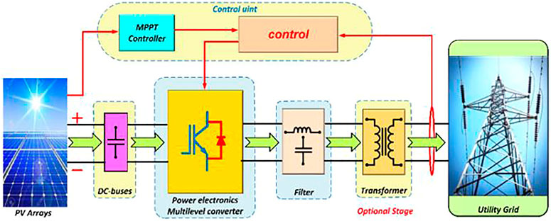
FIGURE 1. Pv system with MLI.
3.2 MPPT objective (PV voltage regulator design)
The characteristics of PV modules are affected by variations in temperature, insolation, and load. As a result, using the MPPT is required to keep the operating voltage in around MPP and to achieve the necessary output voltage having the smallest amount of solar panels feasible (Bhandari et al., 2014). The familiar PO “Perturb and Observe algorithm” approach is utilized to attain the following aims because it is easier and requires minimal measurable parameters. The PV voltage as well as current represents the PO block’s input signals, which result to a PV reference voltage in the output. The boost regulator uses the latter as a references Aourir et al. (2020) and Abouloifa et al. (2018). The PV arrays are being used to supply DC voltages to the technology being examined. The current control method’s goal is to achieve a DC voltage across every solar array’s output that is near to its MPPs, so that the settings of every DC/DC boost converter may be controlled to enhance the PV level voltage that will be utilized subsequently by the CHBMI. The back stepping method describes a regulation approach that allows this goal to be achieved. The back stepping technique is accomplished in two phases to attain the control laws because the subsystems beneath examination contain a comparative degree of two. The recommended topology’s averaged paradigm may be represented as below:
Here, y(1,l) and y(2,l) signify the voltage throughout the PV arrays as well as the boost converters’ input current, correspondingly; and y(3,l) signifies the DC-link voltages. The current of the PV arrays is shown by j(pv,l) respectively.
3.2.1 Step 1
Sub-system stabilization Eq. 17
Time-derivation provides the below tracking error dynamics utilizing Eq. 16 and Eq. 18:
We choose the below candidate Lyapunov function, keeping in mind that the Lyapunov function must be positive and its counterpart must be negative:
Its temporal derivative, in fact, corresponds to:
Here, d_1 shows a design parameter that is positive.
The lth stabilising function linked with the subsystems (9a) is produced as below: Given y_2, l as the lth virtual control input signal and the Lyapunov function Eq. 20 and its dynamic Eq. 21:
Because y_(2, l) is not the real control rule, the second tracking error is proceeded as follows:
Utilizing Eqs 22, 23 and Eq. 21fd21 is changed to:
As a result, the Lyapunov function’s time-derivation updates to:
3.2.2 Step 2
Sub-system stabilization Eq. (18): The error variables f1 and f2must fade away in order to attain the control laws, which attempt to regulate the voltages across the PV modules and increase the input voltages. Time-derivation of the second tracking error using equations Eqs 18, 19 yields:
Assume the enhanced Lyapunov function with the below parameters:
Eqs 26, 25 yield the following:
The goal is to make W2,l negative by selecting the following option:
It is worth noting that d2 shows a positive regulator. The control rules provided by the equation are obtained by combining equations Eqs 26, 29.
The creation of O appropriate gate signals for the control of the O boost DC-DC converters is accomplished by utilizing the control principles given in Eq. 24 to PWM generators.
3.2.3 Proposition
The dynamic behaviour linked with the lth closed loop system in the f1,l, f2,l coordinates may be stated as follows, using the control rules Eq. 31 and the averaged computational formalism provided by equations Eqs 16, 17.
Consequently, the error variables f1,l and f2,l monotonically dissipate.
4 Multi-level inverter for the power quality enhancement and THD reduction
4.1 Inverter topology with configuration
There are four steps to the recommended PV system’s total setup. PV arrays are the initial stage, accompanied by boost DC-DC converters, DC-AC inverters, and finally load. Via voltage feedback control, the boost converters must deliver the necessary voltage level to the inverter. In this study, the suggested MLI was employed as a DC-AC inverter. The inverter’s output could then be utilized to power isolated AC loads. The suggested 31-Level inverter architecture with asymmetrical sources was explained. The boost converter outputs were used as DC sources in this study. Two unidirectional switches TM/S,1 and TM/S,3 one bidirectional switch TM/S,2, and two voltage sources WM/S,2 and WM/S,2 make up every basic unit. Six unidirectional switches were included in the H-Bridge component (TD,1, TD,2, TD,3, TD,4, TD,5, and TD,6).
The topology is able to construct 31 output levels by employing asymmetrical DC sources whose values are picked on the basis of geometric progression having a factor of two. Based on the switching states, the levels were obtained by adding the DC sources in sequence. The topology may operate in either a binary or a trinary series of DC sources, however the former could create the most output levels. Symmetrical sources can also be configured at the expense of a smaller count of output levels. The DC sources must be chosen in the ratio WM,1: WM,2: WS,1: WS,2 = WDC: 2WDC: 4WDC: 8WDC to perform the binary sequence. The suggested topology is not limited to merely producing 31 levels. The setup can be cascaded into as various stages as needed to create a greater degree of output. The following formulas can be used to calculate the count of switching devices (OSX), gate drivers (OH), DC sources (ODC), output levels (OOM), and maximum magnitude of output voltage (wmax):
Here, o shows the count of cascaded stages and k shows the count of basic units. Only even numbers of fundamental units are taken into account. Nevertheless, by deleting any one among the units as well as TD,5 and TD,6, it is still feasible to provide an odd count of fundamental units. The 31-level introduced CMLI for the PV system is shown in Figure 2.
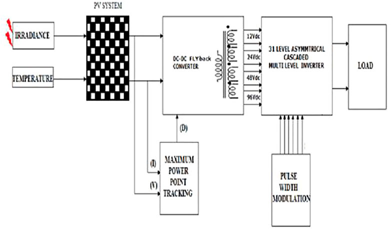
FIGURE 2. 31-level proposed CMLI for the PV system.
4.2 THD
The signal is warped and displays in many shapes, like square, triangular, and saw-tooth waves, underneath this circumstance (Alhafadhi, 2016). Due to the obvious existence of odd as well as even harmonics, the waveform is non sinusoidal, with the former being more harmful than the latter. THD is represented as:
Qois the number of watts. THD is computed as below if the measurement data is in volts:
Wo stands for root mean square voltage. The harmonic count o is represented in both equations. Apart from the numerous benefits of PV solar energy, grid integration of PV systems creates a number of operational issues. Changes in weather temperature and solar irradiance generate oscillations in the PV system’s output power, which are two of the major causes of harmonics. Power electronic components utilized in power converters, in contrast to solar irradiance, causes quality issues like harmonic distortion. The performance of a PV system with respect to power quality is solely dependent on the usage of inverters, solar irradiation, and temperature, all of which can alter the generated voltage, power, and current profiles. Harmonic distortion in PV systems can be caused by both inherent and external factors. Intrinsic harmonic distortions are caused by inverter flaws like control loops and nonlinear component, measurement errors, and low PWM precision (Du et al., 2018 and Sunny and Anto, 2013).
Reactive power and current THD are both connected to output active power levels, which change depending on solar irradiation. The current THD value is risen dramatically all through low irradiance levels (e.g., sunset, sunrise, and cloudy days), but it is noticeably lowered and attains its nominal value. The current distortion behaviour is described by the inherent features of the nonlinear components and control circuit of the PV inverter.
Voltage as well as frequency variations or sag/well patterns in the grid are caused by different power resulting in substantial harmonic distortion (Makbul et al., 2008). Various MPPT algorithms and power electronic topologies have been utilised to overcome these limitations and improve the maturity of innovation in this sector. As a result, a new methodology must be devised to address the aforementioned shortcomings of present methods. Harmonics are problematic not just for the PV module, but also for the overall power supply. THD inside the power signal must be eliminated as much as possible to eradicate this problem.
5 Optimized Recurrent Neural Network and proposed Crow Search-Based Harris Hawks Optimization for the power quality enhancement and THD reduction
5.1 Optimized RNN
Here, the hidden neurons of RNN are tuned by CS-HHO with the consideration of THD minimization thus referred as ORNN. The RNN may be characterised by the below state-space equations when non-linear activation functions are employed for the hidden units and linear activation functions are utilized for the input units:
XJ, XI, XP, T1, and T2 represents weight matrices, while ϕ(l), y(l), d(l), and τ(l) represents the network’s input vectors, hidden units’ outputs, context layer’s outputs, and network’s outputs, accordingly. The following equations are obtained:
Assume q represent the count of input layer units, r represent the count of hidden and context layer units, and s represent the count of output layer units. After that, T1 and T2 are provided by:
I shows the q identity matrix, and K shows a s×rmatrix with complete members equal to 1. Eqs 32–43 when combined produces:
This is in the following format:
L1 = [αKXIXP + γJXI] represents a r×rmatrix, while L2 = [αKXPXJ + γJXJ] represents a r×q matrix. Eq. 10 clearly shows the governing equations of a generic 0th-order system with d as the state vector. During training, the components of L1 and L2 may be changed to fit any arbitrary 0th-order system.
5.2 Proposed CS-HHO
The proposed CS-HHO is used for the THD reduction through the optimization of the hidden neurons of RNN. The cooperative behaviour and pursuit manner of Harris’ hawks in essence, known as surprise pounce, seems to be the fundamental source for HHO (Heidari et al., 2019). The HHO has various advantages such as finding excellent solutions, superior outcomes, etc. It, however limits from binary as well as the multi objective versions, cannot compete distinct constraint solving strategies, etc. Thus, to overcome its limitations, CSA is combined into it and the so formed algorithm is named as CS-HHO. This HHO can handle various strategies as well as solves the multi objective versions of optimization problems, etc. CSA (Askarzadeh, 2016) is a demographically strategy that relies on the premise that crows store their extra food in hiding places and recover it when it is necessary. In CSA, the component of AP is primarily responsible for intensification and diversification. By lowering the AP number, CSA is more likely to focus its search on a small area where a suitable answer is currently available. As a consequence, employing low AP levels boosts intensification. On the other extreme, when the AP value rises, the likelihood of CSA searching in the region of already good solutions drops, and the search space is explored on a global scale (pseudo random). As a reason, using big AP values boosts diversity. The proposed CS-HHO is developed on the basis of AP concept. If AP ≤ 0.5, then the update takes place by CSA as below.
fmj,itr signifies the flight length of crow j at iteration itrand sj defines a random number with uniform distribution between 0 and 1. Otherwise, if AP > 0.5, then the update takes place by exploration phase of HHO as in Eq. 47.
Here, Y (itr + 1) represents the hawks’ position vector, Yrabbit (itr) represents the position of rabbit, Y (itr) represents the current hawks’ position vector, s1, s2, s3, s4, and r represents random numbers, LB and UB represents the upper and lower bounds, Yrd (itr) represents a randomly selected hawk and the average position of the current hawks population is shown by Yn. The pseudocode of CS-HHO is in Algorithm 1.
Algorithm 1. Proposed CS-HHO.
Step 1: Start
Step 2: Population initialization
Step 3: Parameter initialization
Step 4: Fitness calculation
while iter
if AP
else
iter = iter+1
Step 5: Stop
6 Results
6.1 Experimental results
The researched system is built in MATLAB/SIMULINK/SimPowerSystems environment to assess the performance and show proof of the developed regulator. The simulation is run to keep the study focused on cascaded H-bridge cells. The system as well as the simulation parameter of the controller is displayed in Table 1.
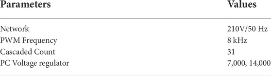
TABLE 1. Simulation parameters.
6.2 PV power analysis
In comparison to real available power and traditional MPPT controller, Table 2 shows total power gathered by the introduced CS-HHO-based MPPT scheme under variable irradiance. Figure 3 shows PV analysis based on proposed method.
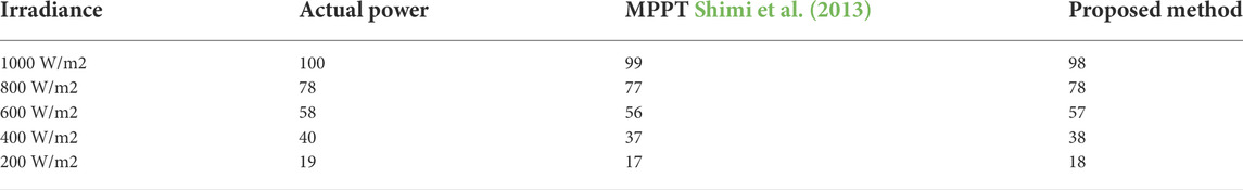
TABLE 2. PV power analysis.
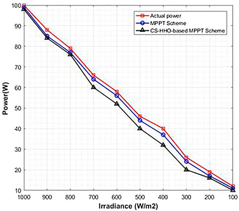
FIGURE 3. PV power analysis.
6.3 Voltage and THD analysis
The harmonic spectrums of the output voltage and current waveforms under testing conditions are shown in Figure 4. THD is 2.86 percent for both voltage and current. This is significantly below the IEEE 519 standard’s 5-percentage-point restriction. The circuit is not activated while employing a totally resistive load since there exists no reactive power component and the power factor is at unity. Excluding the amplitude, the waveforms of voltage as well as current are quite identical. On both waveforms, the 31-level output is readily visible.
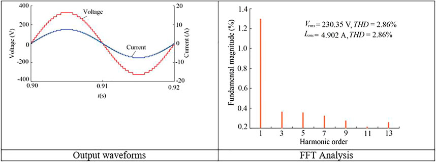
FIGURE 4. Operation beneath full load operation.
6.4 Efficiency analysis
Table 3 shows the efficiency study of the suggested asymmetrical 31-level inverter architecture utilizing the load. Simply multiply the rms current, rms voltage, and power factor yields the output power. The efficiency continues to be amazing. 96.81 percent is the value. The power distributed by the resistive load is identical to the power distributed by the resistive load. When compared to various DC sources, single DC source is determined to be roughly 23 percent higher than the prior source as shown in Figure 5. The power distribution is comparable to what was found in the simulation research. Efficiency is defined as the amount of energy produced divided by the amount of energy input and expressed as a percentage. Ultimately, diminishing harmonics and statistical measurements are used to show that the established procedure is capable throughout entire instances. Similarly, a well-proven approach optimally manages DC connection voltages and collects grid currents.
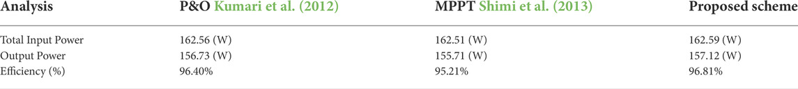
TABLE 3. Efficiency comparison.
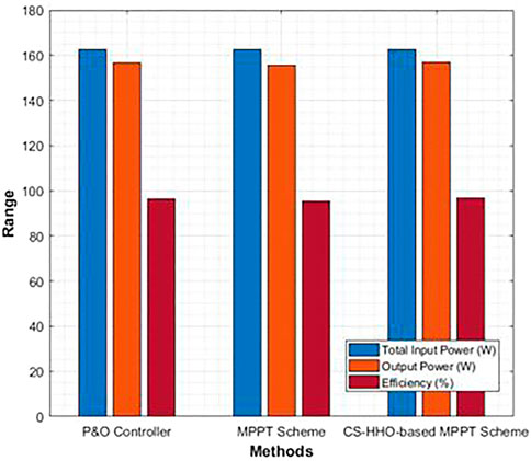
FIGURE 5. Efficiency analysis.
6.5 Statistical analysis
Since the statistical measures are stochastic in nature, it is required to perform the optimization a minimum of five times in order to attain the best optimal solution. In Figure 6, different measures such as mean, median, and standard deviation are considered. The considered measures clearly reveal the betterment of the proposed method in terms of the considered measures than the existing methods as listed in Table 4.
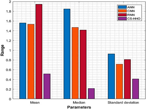
FIGURE 6. Statistical analysis.
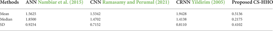
TABLE 4. Statistical comparison.
6.6 Time domain parameter analysis
The time domain parameter analysis in terms of various measures such as settling time, peak time, rise time, and steady state error with respect to methods like ANN, CNN, RNN and introduced CS-HHO is shown in Figure 7. Table 5 clearly reveals that the time utilized is less with the proposed CS-HHO than the other methods. Hence, it can be clearly stated that the time domain parameter analysis is better with CS-HHO than the other methods for the developed PV system with MLI.

FIGURE 7. Time domain parameter analysis.
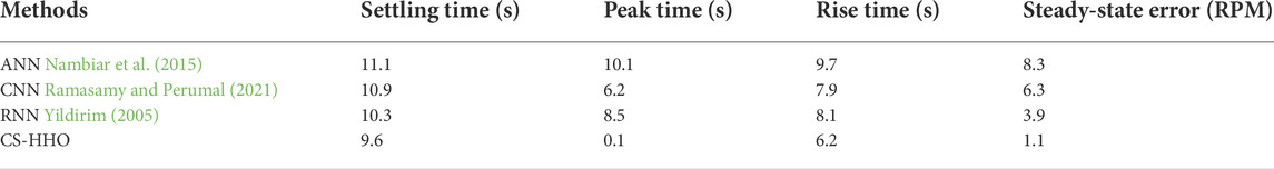
TABLE 5. Time domain parameter analysis Comparison.
7 Conclusion
This paper proposed an artificial intelligence-based PV system optimization concept as well as an unique cascaded MLI for PV system grid integration. The cascaded MLI was the best ideal for PV systems since it has fewer power electronic switches and could operate at asynchronous voltage sources. By increasing the output voltage level, this unique inverter reduced THD at the output. It also enhanced the system’s power quality. ORNN controlled the micro grid integration of the introduced inverter, with hidden neurons tuned by a novel hybrid meta heuristic algorithm that combined CSA and HHO, resulting in CS-HHO. The suggested model was tested under a variety of loads and weather situations. The simulation results validated the created system’s efficiency.
Data availability statement
The original contributions presented in the study are included in the article/supplementary material, further inquiries can be directed to the corresponding author.
Author contributions
All authors listed have made a substantial, direct, and intellectual contribution to the work and approved it for publication.
Conflict of interest
The authors declare that the research was conducted in the absence of any commercial or financial relationships that could be construed as a potential conflict of interest.
The reviewer [IV] declared a shared affiliation with the authors at the time of the review.
Publisher’s note
All claims expressed in this article are solely those of the authors and do not necessarily represent those of their affiliated organizations, or those of the publisher, the editors and the reviewers. Any product that may be evaluated in this article, or claim that may be made by its manufacturer, is not guaranteed or endorsed by the publisher.
References
Abdelsalam, A. K., Massoud, A. M., Ahmed, S., and Enjeti, P. N. (2011). High-performance adaptive perturb and observe mppt technique for photovoltaic-based microgrids. IEEE Trans. Power Electron. 26, 1010–1021. doi:10.1109/TPEL.2011.2106221
Abouloifa, A., Aouadi, C., Lachkar, I., Boussairi, Y., Aourir, M., and Hamdoun, A. (2018). Output-feedback nonlinear adaptive control strategy of the single-phase grid-connected photovoltaic system. J. Sol. Energy 2018, 1–14. doi:10.1155/2018/6791056
Adinolfi, G., Graditi, G., Siano, P., and Piccolo, A. (2015). Multiobjective optimal design of photovoltaic synchronous boost converters assessing efficiency, reliability, and cost savings. IEEE Trans. Ind. Inf. 11, 1038–1048. doi:10.1109/TII.2015.2462805
Alhafadhi, L. A. (2016). “Total harmonics distortion reduction using adaptive, weiner, and kalman filters,”. Ph.D. thesis. Michigan: Scholarworks@WMU.
Aourir, M., Abouloifa, A., Lachkar, I., Aouadi, C., Giri, F., and Guerrero, J. M. (2020). Nonlinear control and stability analysis of single stage grid-connected photovoltaic systems. Int. J. Electr. Power & Energy Syst. 115, 105439. doi:10.1016/j.ijepes.2019.105439
Askarzadeh, A. (2016). A novel metaheuristic method for solving constrained engineering optimization problems: Crow search algorithm. Comput. Struct. 169, 1–12. doi:10.1016/j.compstruc.2016.03.001
Bhandari, B., Poudel, S. R., Lee, K.-T., and Ahn, S.-H. (2014). Mathematical modeling of hybrid renewable energy system: A review on small hydro-solar-wind power generation. Int. J. Precis. Eng. Manuf. -Green. Tech. 1, 157–173. doi:10.1007/s40684-014-0021-4
Bhukya, M., and Kota, V. (2018). DCA-TR-based MPP tracking scheme for photovoltaic power enhancement under dynamic weather conditions. Electr. Eng. 100, 2383–2396. doi:10.1007/s00202-018-0710-z
Bhukya, M. N., Kota, V. R., and Depuru, S. R. (2019). A simple, efficient, and novel standalone photovoltaic inverter configuration with reduced harmonic distortion. IEEE Access 7, 43831–43845. doi:10.1109/ACCESS.2019.2902979
Chandrasekaran, S., Durairaj, S., and Padmavathi, S. (2021). A performance evaluation of a fuzzy logic controller-based photovoltaic-fed multi-level inverter for a three-phase induction motor. J. Frankl. Inst. 358, 7394–7412. doi:10.1016/j.jfranklin.2021.07.032
Dileep, G., and Singh, S. N. (2017). Selection of non-isolated dc-dc converters for solar photovoltaic system. Renew. Sustain. Energy Rev. 76, 1230–1247. doi:10.1016/j.rser.2017.03.130
Du, Y., Lu, D., Zobaa, A., Aleem, S., and Balci, M. (2018). “Harmonic distortion caused by single-phase grid-connected pv inverter,” in Power system harmonics: Analysis, effects and mitigation solutions for power quality improvement. Editors A. F. Zobaa, S. Aleem, and M. E. Balci (Norderstedt, Germany: BoD – Books on Demand), 51.
Eltawil, M. A., and Zhao, Z. (2013). Mppt techniques for photovoltaic applications. Renew. Sustain. Energy Rev. 25, 793–813. doi:10.1016/j.rser.2013.05.022
Fernão Pires, V., Cordeiro, A., Foito, D., and Silva, J. F. (2018). Three-phase multilevel inverter for grid-connected distributed photovoltaic systems based in three three-phase two-level inverters. Sol. Energy 174, 1026–1034. doi:10.1016/j.solener.2018.09.083
Graditi, G., Adinolfi, G., and Tina, G. M. (2014). Photovoltaic optimizer boost converters: Temperature influence and electro thermal design. Appl. Energy 115, 140–150. doi:10.1016/j.apenergy.2013.10.031
Haddadi, A. M., Farhangi, S., and Blaabjerg, F. (2019). A reliable three-phase single-stage multiport inverter for grid-connected photovoltaic applications. IEEE J. Emerg. Sel. Top. Power Electron. 7, 2384–2393. doi:10.1109/JESTPE.2018.2872618
Hamidi, M., Ishak, D., Zainuri, M., and Ooi, C. (2020). An asymmetrical multilevel inverter with optimum number of components based on new basic structure for photovoltaic renewable energy system. Sol. Energy 204, 13–25. doi:10.1016/j.solener.2020.04.056
Hamidi, M. N., Ishak, D., Zainuri, M. A. A. M., Ooi, C. A., and Tarmizi, T. (2021). Asymmetrical multi-level dc-link inverter for pv energy system with perturb and observe based voltage regulator and capacitor compensator. J. Mod. Power Syst. Clean Energy 9, 199–209. doi:10.35833/MPCE.2019.000147
Heidari, A. A., Mirjalili, S., Faris, H., Aljarah, I., Mafarja, M., and Chen, H. (2019). Harris hawks optimization: Algorithm and applications. Future gener. Comput. Syst. 97, 849–872. doi:10.1016/j.future.2019.02.028
Janardhan, K., Mittal, A., and Ojha, A. (2020). Performance investigation of stand-alone solar photovoltaic system with single phase micro multilevel inverter. Energy Rep. 6, 2044–2055. doi:10.1016/j.egyr.2020.07.006
Katir, H., Abouloifa, A., Lachkar, I., Noussi, K., Giri, F., and Guerrero, J. (2020). Advanced nonlinear control of a grid-connected photovoltaic power system using n-cascaded h-bridge multilevel inverters. IFAC-PapersOnLine 53, 12859–12864. doi:10.1016/j.ifacol.2020.12.2095
Killi, M., and Samanta, S. (2015). Modified perturb and observe mppt algorithm for drift avoidance in photovoltaic systems. IEEE Trans. Ind. Electron. 62, 5549–5559. doi:10.1109/TIE.2015.2407854
Kumari, J. S., Babu, D. C. S., and Babu, A. K. (2012). Design and analysis of p&o and ip&o mppt techniques for photovoltaic system. Int. J. Mod. Eng. Res. 2, 2174–2180.
Liu, F., Duan, S., Liu, F., Liu, B., and Kang, Y. (2008). A variable step size inc mppt method for pv systems. IEEE Trans. Ind. Electron. 55, 2622–2628. doi:10.1109/TIE.2008.920550
Macaulay, J., and Zhou, Z. (2018). A fuzzy logical-based variable step size P&O MPPT algorithm for photovoltaic system. Energies 11, 1340. doi:10.3390/en11061340
Mahendiran, T. V. (2020). A color harmony algorithm and extreme gradient boosting control topology to cascaded multilevel inverter for grid connected wind and photovoltaic generation subsystems. Sol. Energy 211, 633–653. doi:10.1016/j.solener.2020.09.079
Makbul, A., Hamid, M. I., and Taufik, T. (2008). “Power quality behavior of single phase fed adjustable speed drive supplied from grid of pv generation,” in 2008 IEEE 2nd International Power and Energy Conference (IEEE), 1098–1102.
Moradi-Shahrbabak, Z., Tabesh, A., and Yousefi, G. R. (2014). Economical design of utility-scale photovoltaic power plants with optimum availability. IEEE Trans. Ind. Electron. 61, 3399–3406. doi:10.1109/TIE.2013.2278525
Motahhir, S., El Hammoumi, A., and El Ghzizal, A. (2018). Photovoltaic system with quantitative comparative between an improved mppt and existing inc and p&o methods under fast varying of solar irradiation. Energy Rep. 4, 341–350. doi:10.1016/j.egyr.2018.04.003
Nambiar, N., Palackal, R. S., Greeshma, K. V., and Chithra, A. (2015). “Pv fed mli with ann based mppt,” in 2015 International Conference on Computation of Power, Energy, Information and Communication (ICCPEIC), India, April 22,23, 2015. 0293–0300 doi:10.1109/ICCPEIC.2015.7259478
Nazer, A., Driss, S., Haddadi, A. M., and Farhangi, S. (2021). Optimal photovoltaic multi-string inverter topology selection based on reliability and cost analysis. IEEE Trans. Sustain. Energy 12, 1186–1195. doi:10.1109/TSTE.2020.3038744
Pai, F.-S., and Chao, R.-M. (2010). A new algorithm to photovoltaic power point tracking problems with quadratic maximization. IEEE Trans. Energy Convers. 25, 262–264. doi:10.1109/TEC.2009.2032575
Ramasamy, S., and Perumal, M. (2021). Cnn-based deep learning technique for improved h7 tli with grid-connected photovoltaic systems. Int. J. Energy Res. 45, 19851–19868. doi:10.1002/er.7030
Shimi, S. L., Thakur, T., Kumar, J., Chatterji, S., and Karanjkar, D. (2013). “Mppt based solar powered cascade multilevel inverter,” in 2013 Annual International Conference on Emerging Research Areas and 2013 International Conference on Microelectronics, Communications and Renewable Energy. 1–5. doi:10.1109/AICERA-ICMiCR.2013.6576041
Sonti, V., Jain, S., and Pothu, B. S. K. R. (2020). Leakage current minimization using npc dc decoupling method for three-phase cascaded multilevel pv inverter. IEEE Trans. Circuits Syst. Ii. 67, 3247–3251. doi:10.1109/TCSII.2020.2984014
Sunny, R., and Anto, R. (2013). Control of harmonics and performance analysis of a grid connected photovoltaic system. Int. J. Adv. Res. Electr. Electron. Instrum. Eng. 2, 37–45.
Wang, L., Wu, Q., and Tang, W. (2017). Energy balance control of a cascaded multilevel inverter for standalone solar photovoltaic applications. Energies 10, 1805. doi:10.3390/en10111805
Yang, Y., and Wen, H. (2018). Adaptive perturb and observe maximum power point tracking with current predictive and decoupled power control for grid-connected photovoltaic inverters. J. Mod. Power Syst. Clean. Energy 7, 422–432. doi:10.1007/s40565-018-0437-x
Yildirim, S. (2005). Design of adaptive robot control system using recurrent neural network. J. Intell. Robot. Syst. 44, 247–261. doi:10.1007/s10846-005-9012-6
Nomenclature
PV photo voltaic
MPPT maximum power point tracking
MLI multi level inverter
THD total harmonic distortion
ORNN Optimized Recurrent Neural Network
CSA crow search algorithm
CC conversion circuit
ANN artificial neural network
CHB cascade h-bridge
HHO harris hawks optimization
PWM pulse width modulation
NPC neutral point clamped
P&O perturb and observe
CS-HHO Crow Search-based Harris Hawks Optimization
SIMO single-input and multi-output
CMLI cascaded multi-level inverter
MLDCL multi-level DC-link
TFL total financial losses
CHA color harmony algorithm
POVR P&O based voltage regulator
XGBOOST eXtreme Gradient BOOSTing
IGBT Insulated Gate Bi-polar swiTches
VSI voltage source inverter
PDPWM phase disposition pulse width modulation
FLC fuzzy logic controller
STC standard test conditions
PI proportional-integral
AP Awareness Probability
Keywords: multi level inverter, power quality enhancement, total harmonic distortion reduction, micro grid integration, Optimized Recurrent Neural Network and Crow Search-based Harris Hawks Optimization, photo voltaic system
Citation: A. P and K. S (2022) Optimized RNN-oriented power quality enhancement and THD reduction for micro grid integration of PV system with MLI: Crow Search-based Harris Hawks Optimization concept. Front. Energy Res. 10:1038533. doi: 10.3389/fenrg.2022.1038533
Received: 07 September 2022; Accepted: 26 September 2022;
Published: 10 November 2022.
Edited by:
Sarat Kumar Sahoo, Parala Maharaja Engineering College (P. M. E. C), IndiaReviewed by:
Indragandhi Vairavasundaram, VIT University, IndiaDeep Kiran, Indian Institute of Technology Roorkee, India
Balamurugan M., Dayananda Sagar College of Engineering, India
Ashish Paramane, National Institute of Technology, Silchar, India
Copyright © 2022 A. and K. This is an open-access article distributed under the terms of the Creative Commons Attribution License (CC BY). The use, distribution or reproduction in other forums is permitted, provided the original author(s) and the copyright owner(s) are credited and that the original publication in this journal is cited, in accordance with accepted academic practice. No use, distribution or reproduction is permitted which does not comply with these terms.
*Correspondence: Sathishkumar K., a2Fuc2F0aGgyMUB5YWhvby5jby5pbg==
†These authors have contributed equally to this work