 Xiu Zhou1
 Tian Tian
- 1Power Science Research Institute of State Grid Ningxia Power Co., Yinchuan, China
- 2Shizuishan Power Supply Company of State Grid Ningxia Electric Power Co., Ltd., Shizuishan, China
- 3Wuhan Pandian Technology Co., Ltd., Wuhan, China
Dissolved gas analysis (DGA) is a common technology used in the on-site maintenance of oil-immersed power transformers in the power industry at present. However, when the content of dissolved gas in the oil reaches the attention value DGA method can effectively diagnose the operating state of the transformer. Due to the lack of gas production data of free gas which was detected when the faults occur, DGA method cannot timely diagnose the transformer status. To solve the above problem, an experimental platform is built for studying the free gas generation law in oil-immersed transformers under discharge faults, and the characteristic free gas information under discharge fault of transformer is obtained through the experiment. It is found that the existing DGA method cannot accurately analyze the types and severity of sudden serious insulation faults. When high-energy partial discharge fault occurred in the equipment, CO, CO2, CH4, and H2 will be collected in large quantities on the oil surface. These four gases can be used as the basis for characterizing high-energy partial discharge faults. When spark discharge occurred in the equipment, C2H6, C2H4, and C2H2 also be collected on the oil surface which can be used as a diagnostic basis for spark discharge. Moreover, it is found that the existing three-ratio method cannot be used for accurate analysis of oil free characteristic gas, so it is necessary to explore new diagnostic methods. The aim of this study is to explore the pattern of free gas production law by experiments when discharge faults occur and to provide data for a new diagnostic method.
Introduction
Oil-immersed transformer is one of the most critical and widely used equipment in power system, the reliability of the power grid mainly depends on the trouble-free operation of the equipment (Tao et al., 2021; Kaliappan and Rengaraj, 2021; Wang et al., 2020).
The oil paper insulation defect is the main reason for the insulation fault of oil-immersed transformer. The insulation fault of power transformer is mainly divided into two types: overheating and discharge, of which discharge fault accounts for a large proportion (Yang, 2010; Chang et al., 2018; Yu et al., 2020). According to the discharge energy density, discharge faults can be divided into three types: high-energy discharge, spark discharge and partial discharge (Zhang et al., 2022). Discharge insulation defects will cause decomposition of insulating oil (mostly mineral oil) and then generate characteristic gases such as CH4, C2H6, C2H2 and H2 (IEEE Power & Energy Society, 2009; International Electrotechnical Commission, 2015). Nowadays, the most common used method to evaluate the operation condition of oil immersed transformer is Dissolved Gas Analysis (DGA) (National Energy Administration, 2015; Li, 2021; Wani et al., 2021). When high-energy discharge occurs in the transformer, the characteristic gas often accumulates in the gas relay before it is dissolved in the oil causing the gas relay to act (Dai et al., 2017). Similarly, for sudden serious insulation faults, the generated characteristic gas is too late to dissolve in the oil and it will escape to the oil surface (Taha et al., 2021). As a result, DGA technology cannot forecast sudden severe insulation effectively (Ravi et al., 2021). The sudden serious insulation fault is the main reason for the explosion of oil-immersed transformer (Yu, 2018), such as the Ultra High Voltage (UHV) Transformer explosion safety accident of Hunan province’s power grid in 2017. By studying the change law of free gas component content, sudden and serious faults can be timely diagnosed.
At present, there is little research on free gas in the power industry. Zhang et al. (2021) proposed a new protection method by studying the relationship between the volume of free gas and the development stage of discharge in 2021, the research results can effectively reduce the safety accidents of transformers, this literature only studies the volume of free gas and the development stage of discharge, and the volume of free gas generated is difficult to measure by current technical means. Zheng et al. (2021) studied the gas production law of free gas with corona discharge model, this literature only studied the free gas production law of the normal discharge defect model, lacks the gas production law of tangential discharge defect model, which is of insufficient significance in engineering.
Based on above situation, two defect models are designed firstly, one is the surface discharge model dominated by normal discharge, and the other is the oil gap discharge model dominated by tangential discharge, which makes up for the significance of research in engineering. Then, the free gas production law under different severity is obtained through experiments, and the existing gas sensors can easily detect the concentrations of seven characteristic gases (Aldhafeeri et al., 2020; Ward et al., 2021). The research results can be applied to the current power industry to reduce the probability of oil-immersed transformer accidents.
Materials and methods
Through the investigation on the escape path of fault characteristic gas of oil-immersed transformer, a simulation experiment platform for free gas detection of transformer sudden severe discharge fault is built, the test circuit is shown in Figure 1.
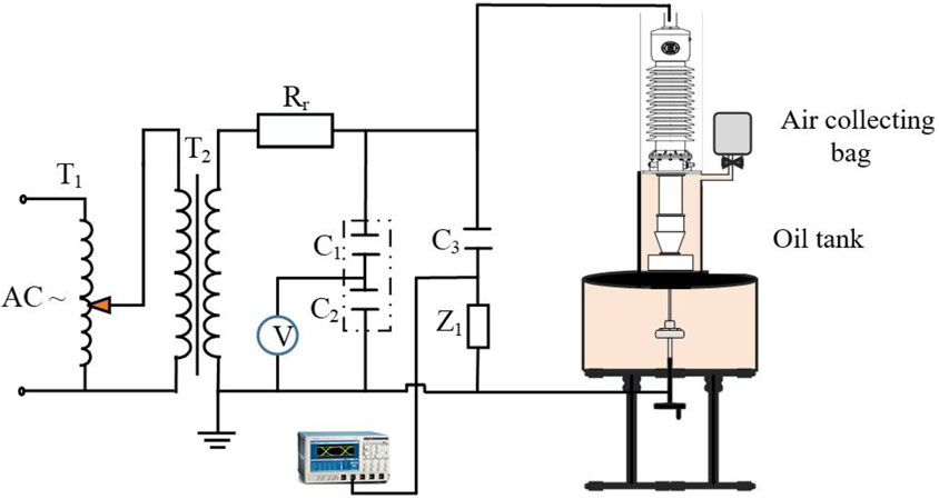
FIGURE 1. Analog experimental circuit for free gas detection of sudden and serious discharge fault of transformer.
In Figure 1, T1 is a voltage regulator with input 220 V power frequency Alternating Current (AC) voltage, T2 refers to power frequency test transformer without partial discharge (YDTCW-1000/2 × 500), C1 and C2 are power frequency capacitive voltage dividers with a voltage division ratio of 1,000:1, Rr is the power frequency test protection resistance (GR1000-1/6), with a resistance value of 10kΩ, which is used to limit the short-circuit current when the test object breaks down; C3 is the coupling capacitance, and its capacitance value is 413.7pf, Z1 is the detection impedance. The air collecting bag is connected to the oil surface of the test object through a rubber hose. During the test, the ambient temperature shall be controlled at 20°C, and the temperature difference between day and night shall be ± 0.7°C.
Due to the complex insulation structure of the transformer, the possible internal discharge locations and types are as follows (Mahmud et al., 2015; Gang et al., 2018):
1. Oil gap discharge in oil diaphragm insulation in the middle of winding;
2. Oil gap discharge at winding end;
3. Partial discharge in oil paper insulation such as lead wire and bonding wire;
4. Partial breakdown of turn-to-turn insulation;
5. Flashover discharge of insulating paper along the surface.
According to the discharge form, characteristics of transformer internal insulation and International Electrical Commission (IEC) 60243 standard (IEC, 2013), two typical discharge defect models are designed. The structure and size of the model are shown in Figure 2.
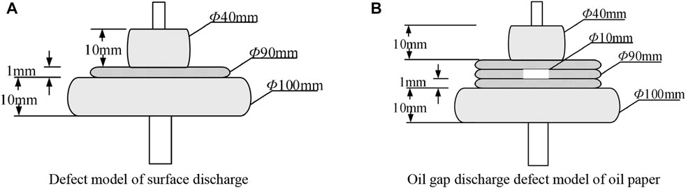
FIGURE 2. Discharge defect model of oil paper. (A) Defect model of surface discharge. (B) Oil gap discharge defect model of oil paper.
The surface discharge defect is composed of two copper plate electrodes with diameters of 100 mm and 40 mm and thicknesses of 10 mm and oil paper with single layer thickness of 1 mm and diameter of 90 mm (Guozhi et al., 2019; Zhang et al., 2022). The oil paper plate is fixed by two plate electrodes. There are two 40 mm diameter pole plates. One is connected to the high voltage terminal, the other is reliably grounded.
The oil gap defect is used to simulate the partial discharge of the oil gap in the oil paper inside the power transformer. The oil gap defect is composed of three layers of oil paper with a thickness of 1 mm. Through holes with a diameter of 10 mm are opened in the oil paper in the space layer. The superimposed oil paper is fixed by two copper plate electrodes with a diameter of 40 mm and 100 mm and a thickness of 10 mm.
In the discharge defect model, the insulating cardboard is dried at 60°C in the temperature control box for 3 days, and then the temperature is raised to 100°C for 3 days to ensure that the cardboard is fully dried without damaging the internal insulation structure. After vacuum oiling for 5 days, the insulating paperboard shall be polished with sandpaper in advance to ensure that the insulating paperboard is free of sharp corners or burrs.
Before the test, it is necessary to determine the initial discharge voltage and breakdown voltage of the oil paper surface discharge defect model and the oil paper oil gap discharge defect model. After placing the set defect in insulating oil, a step-by-step pressurization method is used. When the oscilloscope has a pulse current signal caused by defect’s discharge, then maintain 5 min at this voltage level and observe whether there is a continuous pulsed discharge signal. If the pulse discharge signal persists, then record the voltage level as the initial discharge voltage, otherwise, until a continuous pulse discharge signal appears (Yang et al., 2022). After completing the above steps, continue increasing the voltage, until breakdown occurs in the oil tank. The voltage level at which the breakdown occurs is recorded as the breakdown discharge voltage. The specific test procedure is shown in Figure 3.
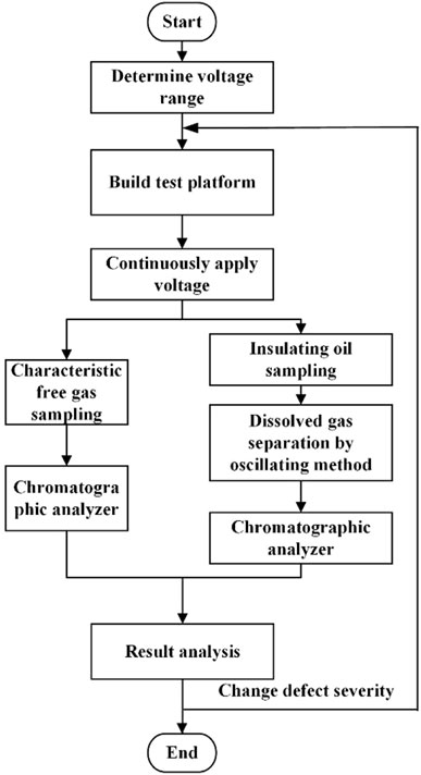
FIGURE 3. Flow chart of free gas detection simulation test for sudden serious discharge fault of transformer.
Pulse current method is the most commonly used insulation detection method for power equipment at present, the International Electrotechnical Commission has formulated a special standard for this method: IEC60270 (IEC, 2000). This method usually measures the electric pulse signal generated by device PD by connecting the coupling device (RL or RLC circuit) to the test object in series or to the coupling capacitor in series, the test method is shown in Figure 4.
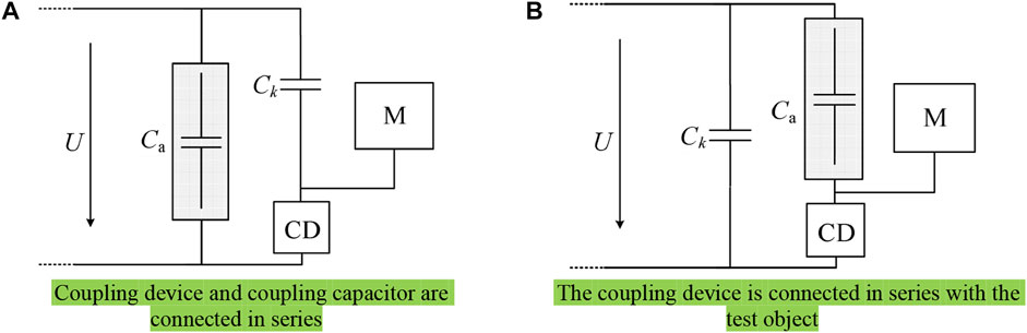
FIGURE 4. Typical pulse current PD measuring circuit. (A) Coupling device and coupling capacitor are connected in series. (B) The coupling device is connected in series with the test object.
After determining the initial discharge and breakdown voltages of both models, select the different levels of voltage between the initial voltage and the breakdown voltage as the test voltage. The defect model was continuously discharged using the constant voltage method, and the defect model is continuously discharged until breakdown. Statistical discharge information every half hour during the test. At the end of the test, the free gas and the dissolved gas were collected and component content was analysed by using a chromatography. Finally adjust the severity of defect discharge, repeating the above steps to obtain gas production laws with different severities.
Main results
Before the test, the initial discharge voltage of the surface discharge defect model is 14 kV, and the breakdown discharge voltage is 21 kV. The initial discharge voltage of the oil gap discharge defect model is 20 kV, and the breakdown discharge voltage is 25 kV.
Discharge characteristics of discharge defect model
Based on the measured initial discharge voltage and breakdown voltage, three test voltage levels of 15 kV, 17 kV, and 19 kV are selected as the test voltage for the surface discharge defect model; and 22 kV, 23 kV, and 24 kV are used as the test voltage of oil gap discharge defect model; set the sampling frequency of the oscilloscope as 20 MS/s. Through calculation, the average discharge capacity per unit time of three test voltage levels of 15 kV, 17 kV, and 19 kV under the surface discharge defect model is 48932 pC/s, 51883 pC/s and 245873 pC/s respectively; under the oil gap discharge defect model, the average discharge capacity per unit time (Bo et al., 2016) of the three test voltage levels of 22 kV, 23 kV, and 24 kV are 124387 pC/s, 283376 pC/s and 365268 pC/s respectively, as shown in Figure 5. It can be seen that the discharge amount of the oil paper surface discharge defect model increases slightly at 15 kV–17 kV, and the discharge amount increases significantly near the breakdown voltage. The discharge quantity of oil gap discharge defect model increases with the increase of voltage level, the discharge amount of the oil gap discharge defect model increases with the increase of the voltage level, and the increment is obvious.
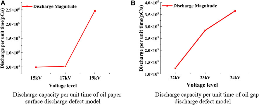
FIGURE 5. Unit time discharge of different voltage levels. (A) Discharge capacity per unit time of oil paper surface discharge defect model. (B) Discharge capacity per unit time of oil gap discharge defect model.
During the test, it was observed that electric sparks and bubbles will appear in the oil tank as shown in Figure 6. When the applied voltage of the oil paper surface discharge defect model is 19 kV. Once the test is completed, cut off the power. Taking out the insulating cardboard of the surface discharge defect model, it is found that there are obvious carbonization traces on the insulating cardboard. As shown in Figure 7, it indicates that the oil paper surface discharge under the test voltage level is spark discharge. In Figures 1, 6 is the bubble generated by test, 2 is the spark generated by spark discharge, 3 is the rod electrode of the surface discharge model, 4 is the insulating card board, 5 is the plate electrode of the surface discharge model.
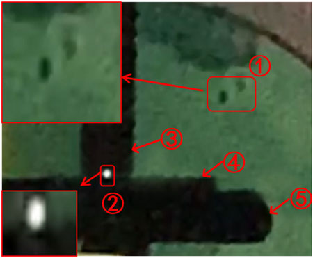
FIGURE 6. Spark discharge and bubble under test voltage grade 19 kV.
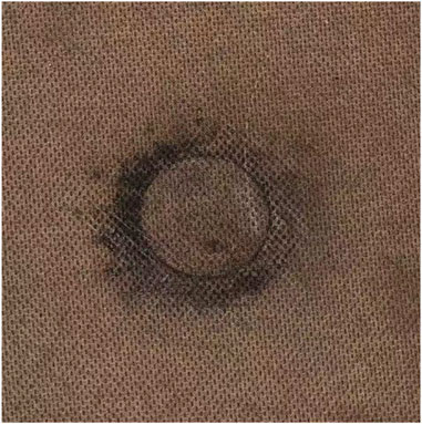
FIGURE 7. Carbonation trace of insulating cardboard.
Gas production law of characteristic gas under different severity of discharge defect model
At the end of the experiment, the collected free gas and dissolved gas are analyzed by oil chromatography respectively. The gas results obtained in the test are obtained through three measurements and the average value is taken. If the results of one measurement are far from those of other measurements, the measurement shall be repeated.
The analysis results are shown in Table 1 and Table 2. The obtained gas sample component concentration data into curves according to different voltage levels, as shown in Figures 8, 9.
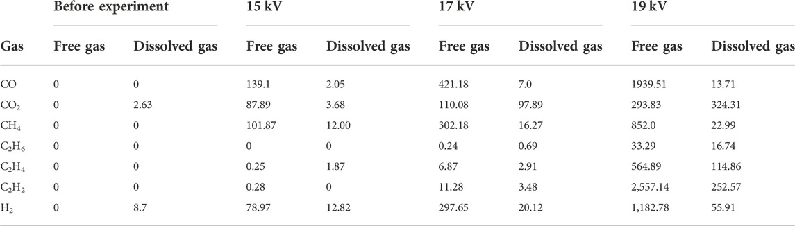
TABLE 1. Surface discharge defect model under different severity of oil surface gas and dissolved gas in oil (unit:
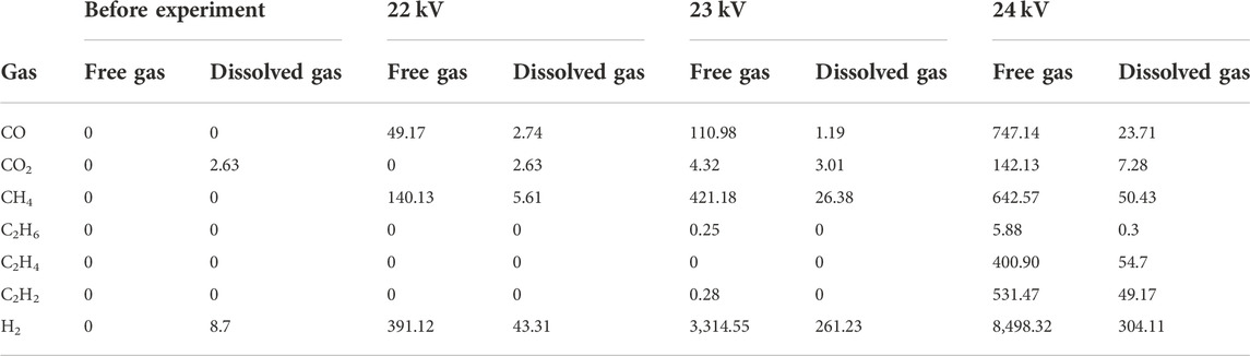
TABLE 2. Oil gap discharge defect model under different severity of oil surface gas and dissolved gas in oil (unit:
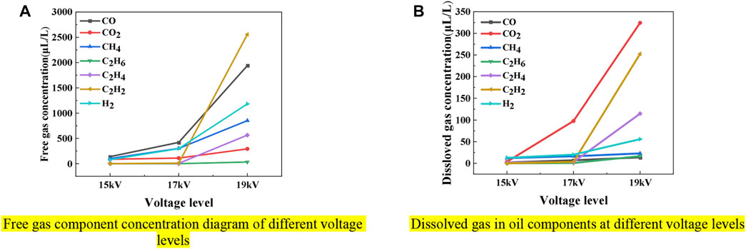
FIGURE 8. Concentration diagram of free characteristic gas and dissolved characteristic gas components in oil. (A) Free gas component concentration diagram of different voltage levels. (B) Dissolved gas in oil components at different voltage levels.
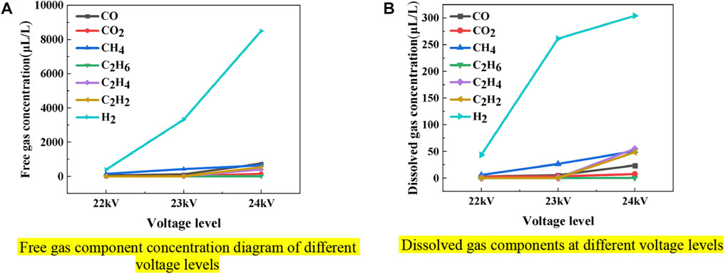
FIGURE 9. Concentration diagram of free characteristic gas and dissolved characteristic gas components in oil. (A) Free gas component concentration diagram of different voltage levels. (B) Dissolved gas components at different voltage levels.
It can be seen from Table 1 and Table 2 that the characteristic gas generated by the surface discharge defect under different test voltage levels will escape to the oil surface in the two defect models. Collecting and testing these gases reveals that the concentrations of some characteristic gases on the surface of the oil are much greater than the concentrations of dissolved gases, although the amount of insulating oil in the oil tank is less than that in the real power transformer. For surface discharge defects, when the discharge energy is low, the characteristic gas produced is mainly CO. But when the voltage level is close to the breakdown voltage, a large amount of C2H2 appears on the oil surface. Meanwhile, the content of C2H2 is the largest, and the severity of the fault can be judged according to the content of C2H2. For oil gap discharge defects, H2 has always been the most productive characteristic gas, and is far greater than other characteristic gases. When the discharge energy is low, there is no C2H6, C2H4 and C2H2 on the oil surface. When the voltage level is 23 kV, a small amount of C2H6 and C2H2 will appear on the oil surface. When the voltage level reaches 24kV, the content of C2H6, C2H4 and C2H2 will increase. At this time, the severity of the fault can be judged according to the content of these three characteristic gases. The test results show that it is feasible to monitor the sudden serious discharge fault of oil-immersed power transformer by detecting the characteristic free gas.
To further, in order to explore whether the characteristic gas is dissolved in the insulating oil, the Ostwald coefficient ki corresponding to the characteristic gas under different discharge severity is calculated. The calculation formula of the Wald coefficient ki is as follows:
In Eq. 1, Coi is the concentration of characteristic gas i dissolved in oil under equilibrium conditions; Cgi is the concentration of characteristic gas i in the gas phase under equilibrium conditions, and the unit of gas concentration is
The comparison results of Ostwald coefficient corresponding to characteristic gas under different discharge severity calculated according to Eq. 1 and standard Ostwald coefficient at 50°C are shown in Table 3.
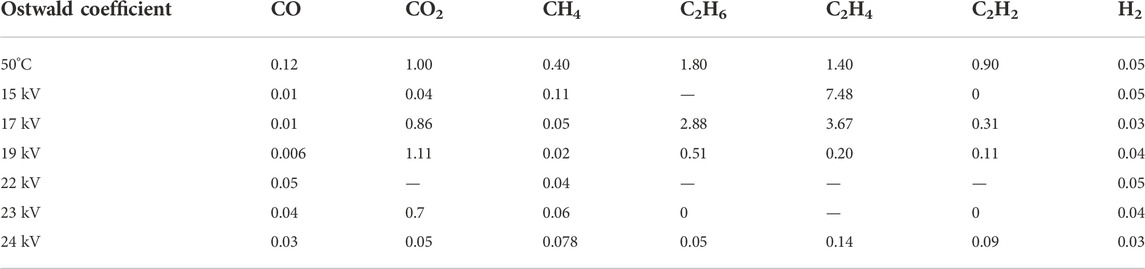
TABLE 3. Ostwald coefficient corresponding to characteristic gas under different discharge severity.
It can be seen from Table 3 that there is a great difference between the standard Ostwald coefficient when sudden severe discharge defects occur in the oil tank and when the temperature is 50°C and sudden severe discharge defects occur in the oil tank, which indicates that the generated characteristic gas cannot be dissolved in the insulating oil in time, and will escape to the oil surface under serious sudden discharge defects. The relationship between the two is no longer in line with the Ostwald coefficient.
In order to explore whether the dissolved gas in the oil and the characteristic free gas can be diagnosed and analyzed by the traditional three-ratio method (Tingfang et al., 2007), the dissolved gas and the characteristic free gas after the test are diagnosed by the three-ratio method. The diagnosis results are shown in Table 4.
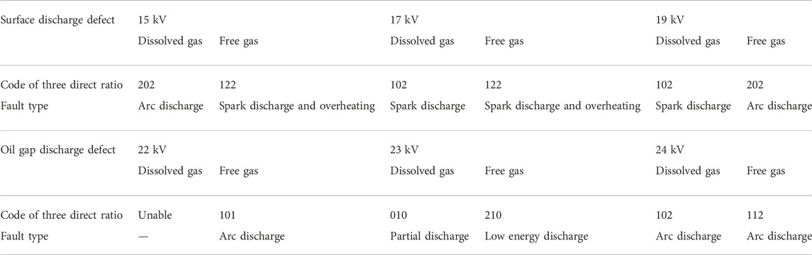
TABLE 4. Diagnostic results of three direct ratio method of dissolved gas in oil and characteristic gas on oil surface.
It can be seen from Table 4 that for the dissolved gas was collected under the surface discharge defect model, the three-ratio method at 15 kV and 17 kV is diagnosed as arc discharge and spark discharge. However, no relevant phenomenon is observed in the oil tank. Although the three-ratio method is diagnosed as spark discharge at 19 kV, the main characteristic gas is not H2 and C2H2 which are given in the guidelines to analyse and judge dissolved gas in transformer oil, and the content of H2 does not reach the attention value. For characteristic free gas, the diagnostic results do not agree with the observed test phenomena. For the dissolved gas in the oil collected under the oil gap discharge defect model, when the fault degree is light, the characteristic gas does not reach the attention value, so the three direct ratio method cannot be used to judge the fault type.
In the case of serious fault, the three direct ratio method is diagnosed as arc discharge. But the actually observed phenomenon is not consistent with the phenomenon of arc discharge, so the existing DGA method cannot timely analyze the status of transformer, a new diagnostic method need to be explored.
In addition, when there is a high-energy partial discharge fault in the equipment, CO, CO2, CH4 and H2 will gather in large quantities on the oil surface, and these four gases can be used as the basis for characterizing the high-energy partial discharge fault. When there is spark discharge in the equipment, the three characteristic gases C2H6, C2H4 and C2H2 will also converge on the oil surface, it can be used as the basis for spark discharge diagnosis.
Conclusion
In this paper, the discharge characteristics of typical defect models in oil-immersed transformers with different severity and the gas production law of free gas are studied. The component concentration of dissolved gas after the test is analyzed and the free gas is collected at the initial stage of the fault of the typical defects actually existing in the transformer. By setting up the test platform of two typical discharge defect model under different severity, the gas production law of free gas was explored of two typical discharge defects:
1. At the initial stage of the fault, the existing DGA technology is difficult to timely diagnose the transformer status. Up till the present moment, there is no method to diagnose the state of transformer according to the content change of free gas. In this study, the free gas production law under discharge fault is obtained through experiments, and the change law of free gas with the aggravation of fault degree is studied.
2. Under the oil paper surface discharge defect model, the oil surface characteristic gas is mainly composed of four characteristic gases C2H2, CO, H2 and CH4. With the aggravation of the fault degree, the characteristic gases C2H4 and C2H6 as high-energy discharge are also collected and detected on the oil surface, and the concentration of the seven characteristic gases also increases with the aggravation of the fault degree.
3. It is found that the traditional three-ratio method cannot get the fault type and severity by analyzing the characteristic free gas. For the dissolved gas in oil, the analysis result of three-ratio method is not accurate because the concentration of dissolved characteristic gas is few at the initial stage of fault. This study provides data support for a new method of transformer status diagnosis by free gas.
Data availability statement
The original contributions presented in the study are included in the article/Supplementary Material, further inquiries can be directed to the corresponding author.
Author contributions
Conceptualization, XZ and TT; Methodology, NL; Software, JB and NL; Validation, PZ, TT, and YL; Formal analysis, YL; Investigation, XL; Resources, NH; Data curation, XL; Writing—original draft preparation, PZ; Writing—review and editing, SJ; Visualization, XZ; Supervision, XZ; Project administration, SJ.
Funding
Project Supported by State Grid Ningxia Electric Power Co., Ltd. (Item code: 5229DK20004S).
Conflict of interest
Authors XZ, TT, JB, YL, XL, and NH were empolyed by the company Power Science Research Institute of State Grid Ningxia Power Co. Authors PZ and NL were empolyed by the company Shizuishan Power Supply Company of State Grid Ningxia Electric Power Co., Ltd. Author SJ was empolyed by the company Wuhan Pandian Technology Co., Ltd.
The authors declare that this study received funding from Electric Power Institute of State Grid Ningxia Electric Power Co. Ltd. The funder had the following involvement in the study: Data acquisition and analysis.
Publisher’s note
All claims expressed in this article are solely those of the authors and do not necessarily represent those of their affiliated organizations, or those of the publisher, the editors and the reviewers. Any product that may be evaluated in this article, or claim that may be made by its manufacturer, is not guaranteed or endorsed by the publisher.
Abbreviations
AC, alternating current; DGA, dissolved gas analysis; IEC, international electrical commission; UHV, ultra high votage.
References
Aldhafeeri, T., Tran, M. K., Vrolyk, R., Pope, M., and Fowler, M. (2020). A review of methane gas detection sensors: Recent developments and future perspectives. Inventions 5 (3), 28. doi:10.3390/inventions5030028
Bo, Q., Zhen, W., Chengrong, L., Qing, Y., Yi, G., and Xiaohan, Z. (2016). Surface discharge phenomena and characteristics of oil paper insulation in AC/DC composite electric fields [J]. J. Electr. Eng. 31 (10), 59–67. doi:10.19595/j.cnki.1000-6753.tces.2016.1007
Chang, S., Xiao, J., Zipin, L., Junran, Z. Y., and Shuwei, F. (2018). A CEEMDAN based noise diagnosis method for distribution transformer discharge fault. High. Volt. Tech. 44 (08), 2603–2611. doi:10.13336/j.1003-6520.hve.20180731019
Dai, J., Song, H., Sheng, G., and Jiang, X. (2017). Dissolved gas analysis of insulating oil for power transformer fault diagnosis with deep belief network. IEEE Trans. Dielect. Electr. Insul. 24 (5), 2828–2835. doi:10.1109/tdei.2017.006727
Gang, L., Ke, W., Shuqi, Z., Zhigang, Z., Jinzhong, L., Huanchao, C., et al. (2018). Development characteristics and phase identification method of surface discharge defects of transformer oil paper insulation. Power Grid Technol. 42 (10), 3451–3458. doi:10.13,335/j.1000-3673.pst.2018.0701
Guozhi, Z., Zhang, X., Xingrong, H., Jia, Y., Tang, J., Yue, Z., et al. (2019). On-line monitoring of partial discharge of less-oil immersed electric equipment based on pressure and UHF. IEEE Access 7, 11178–11186. doi:10.1109/access.2019.2892601
IEEE Power & Energy Society (2009). C57. 104-2008 IEEE guide for the interpretation of gases generated in oil-immersed transformers[S]. USA: IEEE.
International Electrotechnical Commission (2015). IEC 60599 Mineral oil-impregnated electrical equipment in service-guide to the interpretation of dissolved and free gases analysis[S]. Geneva: IEC.
Kaliappan, G., and Rengaraj, M. (2021). Aging assessment of transformer solid insulation: A review[J]. Mater. Today Proc. 47, 272–277.
Li, K. (2021). Fault diagnosis method of oil immersed transformer based on deep learning [D]. North China: North China Electric Power University.
Mahmud, S., Chen, G., Golosnoy, I. O., Wilson, G., and Jarman, P. (2015). Experimental studies of influence of DC and AC electric fields on bridging in contaminated transformer oil. IEEE Trans. Dielect. Electr. Insul. 22 (1), 152–160. doi:10.1109/tdei.2014.004573
National Energy Administration (2015). DL/T 722-2014 Guide to the analysis and the diagnosis of gases dissolved in transformer oil[S]. Beijing: China Electric Power Press.
Ravi, V., Alazab, M., Srinivasan, S., and Arunachalam, A. (2021). Adversarial defense: DGA-based botnets and DNS homographs detection through integrated deep learning[J]. IEEE Trans. Eng. Manag. 99, 1–18. doi:10.1109/TEM.2021.3059664
Taha, I. B. M., Ibrahim, S., and Mansour, D. E. A. (2021). Power transformer fault diagnosis based on DGA using a convolutional neural network with noise in measurements. IEEE Access 9, 111162–111170. doi:10.1109/access.2021.3102415
Tao, J., Fan, H., Jizhong, L., Hua, Y., Hong, L., Xiaoman, L., et al. (2021). Error analysis of winding structure simplification in calculation of hot spot temperature rise of oil immersed transformers [J]. High. Volt. Appar. 57 (11), 156–163+170. doi:10.13296/j.1001-1609.hva.2021.11.020
Tingfang, Y., Pei, L., Jinglu, L., and Yi, H. (2007). Diagnosis of transformer faults by FCM combined with IEC three ratio method [J]. High. Volt. Tech. 08, 66–70. doi:10.13,336/j.1003-6520.hve.2007.08.014
Wang, G., Liu, Y., Chen, X., Yan, Q., and Zhang, J. (2020). Power transformer fault diagnosis system based on Internet of Things[J]. EURASIP J. Wirel. Commun. Netw. 2021 (1), 1–24. doi:10.21203/rs.3.rs-71379/v1
Wani, SA, Rana, A. S., Sohail, S., Rahman, O., Parveen, S., and Khan, S. A. (2021). Advances in DGA based condition monitoring of transformers: A review. Renew. Sustain. Energy Rev. 149, 111347. doi:10.1016/j.rser.2021.111347
Ward, S. A., El-Faraskoury, A., Badawi, M., Ibrahim, S. A., Mahmoud, K., Lehtonen, M., et al. (2021). Towards precise interpretation of oil transformers via novel combined techniques based on DGA and partial discharge sensors. Sensors 21 (6), 2223. doi:10.3390/s21062223
Yang, J. (2010). Study on partial discharge characteristics and gas production law of typical insulation defects in transformer[D]. China, Chong Qing Shi: Chongqing University.
Yang, L., Ming, D., Yadong, X., Yizhuo, H., Yingjie, X., Ming, R., et al. (2022). Development law and phase characteristics of multiphysical signals of oil paper insulation surface discharge [J/OL]. Chin. J. Electr. Eng., 1–12.
Yu, C. (2018). Research on cross sensitivity suppression method of dissolved gas sensor array detection in transformer oil [D]. China, Chong Qing Shi: Chongqing University.
Yu, C., Huijuan, H., Lei, S., Tao, Q., Gehao, S., and Xiuchen, J. (2020). Power transformer fault diagnosis method considering unbalanced case samples[J]. High. Volt. Tech. 46 (01), 33–41. doi:10.13336/j.1003-6520.hve.20191227004
Zhang, H., Zhang, G., Zhang, X., Tian, H., Lu, C., Liu, J., et al. (2022b). PD flexible built-in high-sensitivity elliptical monopole antenna sensor. Sensors 22 (13), 4982. doi:10.3390/s22134982
Zhang, S., Zhang, G., Lu, C., Tian, H., Liu, J., and Zhang, X. (2022a). Flexible planar monopole built-in GIS PD sensor based on meandering technology. Sensors 22 (11), 4134. doi:10.3390/s22114134
Zhang, Y., Hao, Z., Zheng, Y., Pan, S., Li, B., Xue, Z., et al. (2021). “Developing characteristics of oil-immersed transformer internal fault with dignostic method using convergence patterns of free gas[C],” in 2021 IEEE 2nd China International Youth Conference on Electrical Engineering (CIYCEE) (IEEE), 1–6.
Keywords: transformer, discharge faults, free gas, production law, DGA
Citation: Zhou X, Tian T, Liu N, Bai J, Luo Y, Li X, He N, Zhang P and Jun S (2023) Research on gas production law of free gas in oil-immersed power transformer under discharge fault of different severity. Front. Energy Res. 10:1056604. doi: 10.3389/fenrg.2022.1056604
Received: 29 September 2022; Accepted: 09 November 2022;
Published: 17 January 2023.
Edited by:
Srete Nikolovski, Josip Juraj Strossmayer University of Osijek, CroatiaReviewed by:
Ravi Samikannu, Botswana International University of Science and Technology, BotswanaSuwarno Suwarno, Bandung Institute of Technology, Indonesia
Copyright © 2023 Zhou, Tian, Liu, Bai, Luo, Li, He, Zhang and Jun. This is an open-access article distributed under the terms of the Creative Commons Attribution License (CC BY). The use, distribution or reproduction in other forums is permitted, provided the original author(s) and the copyright owner(s) are credited and that the original publication in this journal is cited, in accordance with accepted academic practice. No use, distribution or reproduction is permitted which does not comply with these terms.
*Correspondence: Tian Tian, dGl0YW45MDEyQDE2My5jb20=