 Markus Albertz1†
 Rajesh Goteti
- 1Aramco Americas, Aramco Research Center, Houston, TX, United States
- 2Eastern Area Exploration Department, Saudi Aramco, Dhahran, Saudi Arabia
Geologic carbon storage (GCS) is a fundamental pillar of carbon management that helps mitigate greenhouse gas emissions and addresses the negative effects of climate change. Viable CO2 storage sites share some of the same elements required for successful petroleum systems. For example, while reservoir, seal, and trap are required, migration pathway and timing are not important for CO2 storage, because rather than withdrawing fluid from a trap, CO2 storage involves injection into a geologic trap. Conceptually, this represents a form of reverse production. Numerous petroleum traps around the world, as well as naturally occurring CO2-producing fields and natural gas storage sites attest that safe, long-term storage is possible. Research over the past two decades identified five methods of Geologic Carbon Storage which have been validated through several demonstration and pilot projects around the world: (1) storage in depleted oil and gas fields, (2) use of CO2 in enhanced hydrocarbons recovery (3) storage in saline formations/aquifers, (4) injection into deep unmineable coal seams, and (5) in-situ/ex-situ carbon mineralization. The greatest volumetric potential for GCS is found in saline aquifers which are present throughout the world’s sedimentary basins.
1 Introduction
It is now widely believed that human CO2 emissions have thrown the natural carbon cycle, where CO2 resulting from all natural and anthropogenic carbon sources is taken up by CO2 sinks, out of balance. As a consequence, a large fraction of the approximately 39 Gt of CO2 that are emitted on an annual basis resides in the atmosphere (Friedlingstein et al., 2022). A recent report published by the Intergovernmental Panel on Climate Change (IPCC) concluded unequivocally that human influence resulted in unprecedented climate warming, and that the warming is driven by greenhouse gas emissions (IPCC, 2021). Figure 1A illustrates the observed and modeled warming since 1850 and clearly demonstrates the temperature response to human and natural factors. Figure 1B shows the perturbation of the global carbon cycle caused by anthropogenic activities resulting in the addition of about 19 GtCO2 to the atmosphere per year (Friedlingstein et al., 2022).
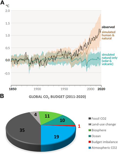
FIGURE 1. (A). Changes in global surface temperature over the past 170 years (black line) compared to climate model simulations of human and natural drivers (brown line), and to only natural drivers (green line). Colored shades show the likely ranges. Reproduced from the sixth assessment report of the Intergovernmental Panel on Climate Change (IPCC, 2021). (B). Global Carbon Budget 2021 (Friedlingstein et al., 2022) illustrated as a pie chart. Fossil and land-use CO2 sources shown in gray tones. Biosphere and Ocean CO2 sinks shown in green colors. Atmospheric CO2 shown in blue. CO2 budget imbalance due to measurement errors shown in red.
This article provides a current snapshot of geologic carbon storage (GCS) options. What is carbon dioxide (CO2)? As is commonly known, CO2 is a colorless, odorless, and incombustible gas at atmospheric pressures and room temperature. CO2 results from the oxidation of carbon and is produced during respiration by all animals, fungi, and microorganisms. It is used in a variety of industries, for example as a solvent (Valluri et al., 2022), an anesthetic, a food packaging gas (Lee et al., 2016), and a refrigerant (Bansal et al., 2012). Most relevant to this study, CO2 forms by burning of fossil fuels and it enters the atmosphere as an important greenhouse gas.
First, we summarize the defining characteristics of a successful geological CO2 storage site. Subsequently, five proven methods of geological CO2 storage are briefly discussed: (1) Depleted oil and gas reservoirs, (2) Use of CO2 in enhanced hydrocarbon recovery, (3) Saline formations/aquifers, (4) Coal seams, and (5) In-situ/ex-situ carbon mineralization.
2 Characteristics of a successful CO2 storage site
Before examining the geological CO2 storage site requirements, the elements of a successful petroleum system are presented in a simplified manner. The genesis of a petroleum system begins with the deposition of a source rock rich in organic matter. Afterwards, a reservoir rock with the potential to preserve appropriate porosity and permeability upon burial is deposited. The sedimentation sequence ends with a seal unit, commonly referred to as cap rock, with very low porosity and permeability. Figure 2A captures this sedimentary sequence. The next step in the development is an event that creates a petroleum trap. For example, folding associated with horizontal compression can create anticline shapes, which often act as traps. Sometimes, however, seals are deposited after trap formation or even after partial erosion have taken place. Successive deposition of sediment layers leads to progressively deeper burial of the source rock. Due to the geothermal gradient, at a certain burial depth, temperatures are sufficiently high to convert kerogen in the source rock to hydrocarbons. In order to fill the trap with oil and/or gas, a migration pathway has to be present. Figure 2B illustrates these elements. Lastly, the relative timing of all of the above steps needs to be favorable for a successful petroleum system to form. For example, if burial is not deep enough for maturation to occur, or if a seal rock is deposited after migration, a trap will not be filled because petroleum would not have formed or it would have escaped, respectively.
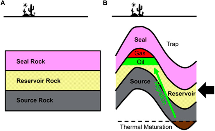
FIGURE 2. Simplified illustration of the key elements of a successful petroleum system. (A). Deposition of source, reservoir, and seal rocks. (B). Folding creates a petroleum trap. A migration pathway must exist to fill a trap with oil and/or gas.
A successful CO2 storage site necessitates the same elements as a petroleum system, except a source rock and a migration pathway. In other words, a CO2 storage site requires a reservoir rock, a seal rock, and a trapping configuration.
Another key difference with hydrocarbon projects is the requirement to characterize and monitor seal performance because seal efficacy is unknown unless it has been geologically proven by the presence of hydrocarbons or some other trapped fluids, for example via pore pressure measurements. In addition to data acquisition at the site characterization stage, long-term monitoring should be put in place to prove that any CO2 leakage from the sequestration site is zero or within allowable tolerance (Roberts and Stalker, 2020).
Clearly, the existence of petroleum traps around the world demonstrates that buoyant fluids such as oil or gas can be entrapped for millions of years in the subsurface. Besides entrapping petroleum fluids, geologic structures can also trap CO2. As a result of magma degassing and metamorphism of carbonates, naturally occurring CO2 fields are present on nearly all continents (Holloway et al., 2005; Miocic et al., 2016). Some of these fields have stored CO2 for up to 70 million years (Stevens and Tye, 2007), proving that CO2 storage in geologic formations is not only technically viable but it is in fact a natural process. Several natural CO2 fields are commercially exploited, for instance, to enable CO2-enhanced oil recovery (EOR) in petroleum fields. For example, the McElmo Dome in Colorado, United States, contains approximately 1.6 billion tons of nearly pure CO2 (96%–98%) and produces about 15 million tons per year from 41 wells (Zabel, 1955; Thomaidis, 1978; Gerling, 1983; Cappa and Rice, 1995; Stevens et al., 2005). CO2 from McElmo Dome has been re-injected for EOR in the Permian Basin, Texas, for more than 30 years (Holloway et al., 2005; Stevens et al., 2005). McElmo Dome is generally viewed as the best analog for geologic CO2 storage sites for depleted oil and gas fields (Stevens et al., 2005; Stevens and Tye, 2007).
CO2 at McElmo Dome is stored in a 75–90 m thick lower Carboniferous carbonate reservoir at about 2,300 m depth. The overlying caprock consists of 400 m thick halite and there is no evidence of CO2 leakage into overlying strata (Stevens et al., 2005). Several faults perturb the reservoir, but they do not extend across the caprock. Figure 3 illustrates the geological key aspects of McElmo Dome. Although McElmo Dome may be the most commonly cited example of a natural CO2 field, there are several others that are well documented, such as the St. Johns field, Arizona/New Mexico (Holloway et al., 2005), and the Bravo Dome in New Mexico (Sathaye et al., 2014).
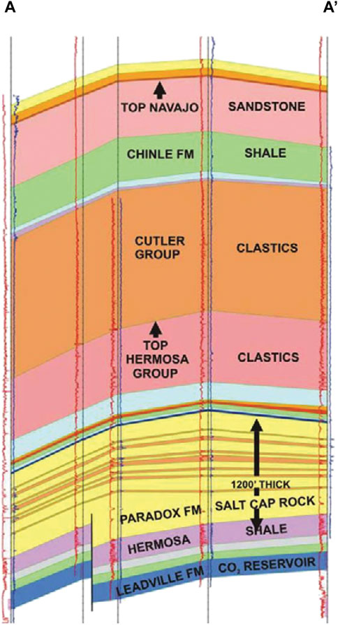
FIGURE 3. Simplified cross-section of the McElmo Dome (Stevens, 2005), illustrating the geometric arrangement of the carbonate reservoir (Leadville Limestone) containing CO2, the overlying evaporite caprock (Paradox Formation), and one fault affecting the reservoir but not the seal.
Furthermore, natural gas has been stored in depleted oil and gas reservoirs (e.g., Stuart, 1991), saline formations, and salt caverns for almost 100 years and in many parts of the world to provide for peak demand and to balance seasonal fluctuations in gas supply (IPCC, 2005). The great majority of storage projects are safe and successful, though a few have leaked gas, due to well integrity issues or leaky faults (IPCC, 2005). Gas storage projects are typically more complex than CO2 storage projects because of the highly flammable and explosive properties of gas, and there are highly variable but sometimes frequent cycles of injection and extraction. CO2 leakage risk is high if concentrations are high (Holloway et al., 2007), or if pressures are high, for instance in pipeline and injection systems (Huang et al., 2014). Also, a number of these facilities, such as the Berlin Natural Gas Storage Facility (IPCC, 2005), are in areas of high population density, which would not be the case for a remote onshore or an offshore CO2 sequestration site. Therefore, in addition to natural CO2 fields, existing natural gas storage facilities in geologic formations offer excellent opportunities to study and design CO2 sequestration sites. In addition, much can be learned about seal capacity and storage potential from ongoing research devoted to hydrogen storage in salt caverns and porous formations (e.g., Matos et al., 2019; Lankof et al., 2022). In the following section, five methods of geologic carbon storage are discussed briefly.
3 Geologic carbon storage options
Five methods of geologic carbon storage have been shown to be technically viable, and some are employed as pilot, demonstration, or even full-scale projects (the majority of active projects in the 25 years to date are reviewed by Zhang et al., 2022): (1) storage in depleted oil and gas fields, (2) use of CO2 in enhanced hydrocarbon recovery, (3) storage in saline formations/aquifers, (4) injection into deep unmineable coal seams, and (5) in-situ/ex-situ carbon mineralization. Each of these methods is briefly described below.
3.1 Carbon storage in depleted oil and gas fields
Depleted oil and gas reservoirs are commonly viewed to be excellent sites for CO2 storage for several reasons (Jenkins et al., 2012): (1) They prove long-term hydrocarbon retention by demonstrating the capacity for buoyant fluids to be trapped in the subsurface, (2) the structure and properties of oil and gas fields have been extensively studied, (3) there usually is widespread documented production history, and (4) the existing infrastructure and wells may be used for handling CO2 operations (IPCC, 2005). Despite geomechanical effects owing to reservoir compaction, carbon storage in depleted fields can be thought of as “reverse production”. Despite the technical appeal, however, no large-scale CO2 storage projects in depleted reservoirs have been deployed anywhere in the world. A few CO2 injection pilot projects have been completed, with monitoring still ongoing, such as the Otway project in Australia (Underschultz et al., 2011). However, their total stored CO2 volume is relatively small compared to the required storage volumes of industrial-scale sequestration projects. A further problem with repurposing ageing or abandoned hydrocarbon fields is that the wellbore integrity is unknown. Large hydrocarbon fields may have thousands of drilled wells and the quality of annular cement may have deteriorated since the well was drilled or may never have been documented in the first place (Zhang and Bachu, 2011). As a result, the top seal that originally trapped hydrocarbons and is a key feature of the longevity of CO2 sequestration may have been compromised by many hundreds of human-made channels (Davies et al., 2014; Kiran et al., 2017).
For example, the Lacq-Rousse project in southwestern France aims to demonstrate the technical feasibility and reliability of an integrated CO2 capture, transportation, injection and storage effort (Prinet et al., 2013). From 2009 to 2013, 51,000 tons of CO2 were injected into a carbonate reservoir at 4500 m depth. The reservoir is overlain by a mudstone formation. A comprehensive monitoring plan was implemented, some stages of which are still ongoing. Monitoring encompasses CO2 stream composition, CO2 atmospheric concentration at the injection well, well annulus pressure, pressure and temperature along the injection well and in the reservoir, microseismicity, soil gas, ground and surface water quality, and fauna and flora biodiversity. To date, no CO2 leakage has been identified.
Another example of a completed small-scale CO2 demonstration storage project in a depleted reservoir is the Otway project in Australia. From 2008 to 2011, 65,000 tons of CO2 were injected into a depleted sandstone reservoir that is capped by a mudstone (Cook, 2014). Similar to Lacq-Rousse, an extensive monitoring program was deployed. Seismic monitoring was conducted, but due to the low volume of CO2 injected, it was not detected. Microseismic as well as pressure and temperature sensors in the monitoring well failed, limiting the data collection to the injection well (IEAGHG, 2017). Successful groundwater monitoring, logging, and analyzing downhole fluid samples showed containment of CO2 in the subsurface.
3.2 Use of CO2 in enhanced hydrocarbon recovery
CO2 enhanced oil recovery (EOR) is a technology applied to depleting oil reservoirs in order to enable additional oil recovery and extend the field life. The main principles of CO2-EOR rely on the fact that CO2 acts as a solvent and that it is miscible with oil, while water and oil are immiscible. CO2 causes oil to swell and lower its viscosity, allowing more oil to flow to a producing well (NETL, 2010). It is important to understand that the boundary between depleting and depleted reservoir is often unclear. For instance, the technical and economic limits to recovery may vary significantly based on the geography, the local regulatory framework, production methods and history, and the geologic attributes of the formation. In contrast to the additional cost without return associated with carbon storage in depleted fields, CO2-EOR in depleting fields usually is desirable because it increases profitability.
CO2-EOR was first used in 1972 in the SACROC (Scurry Area Canyon Reef Operators Committee) Unit in the Permian Basin in Texas (Langston et al., 1988). Due to very low recovery efficiency (∼4.5% of the original oil in place), as a result of rapidly dropping reservoir pressure, CO2-EOR was identified as a means to improve recovery. Shortly after CO2 injection was initiated in 1972, oil production rates improved substantially (Figure 4). As of 2019, about 150 Mt of CO2 were injected into a Permian carbonate reservoir. 75 Mt of CO2 were recovered and recycled, with the balance to be permanently sequestered. Field-based groundwater studies by the Gulf Coast Carbon Center concluded that, despite > 35 years of CO2 injection, drinking water quality has not been adversely impacted (Gerling, 1983).
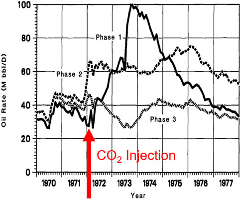
FIGURE 4. SACROC oil production rates with initial CO2 injection overlain. Modified after Langston et al. (1988).
Another successful CO2-EOR project was conducted in the Weyburn Field in Canada. Weyburn is a large international research project supported by 15 industry and government sponsors and consulting organizations with a budget of about 40 million Canadian Dollars (Preston et al., 2005). More than 35 million tons of CO2 have been injected since 2000, with a target of 45 million tons (Sacuta et al., 2015). It is estimated that an additional 130 Mbbls of oil will be recovered via CO2-EOR, extending the field life by 25 years. Figure 5 schematically illustrates the geological configuration of the Weyburn field.
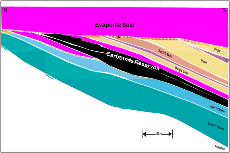
FIGURE 5. Simplified representation of the geological configuration of the Weyburn CO2-EOR site in Canada. Carbonate reservoirs are shaded black. Evaporite seal units are shown in magenta. Inset shows how CO2 flooding is forecasted to recover additional oil volumes extend the field life (Modified after Whittaker, 2005; Erikson, 2020).
A further example of a CO2-EOR demonstration project is the Uthmaniyah Field, Saudi Arabia (Kokal et al., 2016). More complex CO2 injection scenarios involving water-alternating-gas injection for EOR have been considered, but demonstrations are not yet available (Wang et al., 2020).
How much CO2 is permanently sequestered during CO2-EOR and does this amount offset the CO2 emitted during the operation? It is important to recognize that CO2 emissions result from energy consumption throughout an EOR operation as well as from the transport, processing, and combustion of the additional oil produced. During CO2-EOR the produced CO2 is separated, re-injected into the reservoir, and the process is repeated in a loop. Hence, quantifying the ultimate CO2 storage capacity of EOR projects begs the question of whether the oil can be classified as Net Carbon Negative (Nuñez-López et al., 2019). A recent study examined multiple CO2-EOR scenarios and found that all of them start operating with a negative carbon footprint but ultimately generate a positive carbon footprint (Nuñez-López et al., 2019). The authors also found that the net carbon balance is highly variable among different EOR settings and also through time within a single setting. For these reasons, it is desirable to conduct an analysis of expected CO2 footprint (for any carbon storage method) from start to closure of an operation and seek opportunities to continuously optimize CO2-EOR and geologic carbon storage.
Analogous procedures for enhanced gas recovery (EGR) is less widely practiced but some demonstration projects exist (Liu et al., 2022). In this scenario, CO2 is injected close to the base of the gas column and provides additional pressure and piston displacement of the gas towards updip producers. Three demonstration projects exist to date, the longest running being the K12-B project in the Dutch North Sea which began injecting CO2 in 2004 and has injection potential of approximately 20 kt per year (Vandeweijer et al., 2020).
3.3 Geologic carbon storage in saline formations/aquifers
Saline formations or aquifers are any sedimentary layers with brines containing high concentrations of dissolved salts, making them unsuitable for use as drinking water. Typically, the amount of total dissolved solids in such formations exceeds 10,000 mg/L (Garcia et al., 2010). Carbon storage in saline aquifers generally requires the same geological elements as depleted oil and gas fields and/or depleting reservoirs, namely, a CO2 storage reservoir with sufficient porosity and permeability, a sealing cap rock, and a trapping configuration. However, very broad and gently folded, or even flat geometries are suitable as well. These saline aquifers may be confined (valid topseal) or unconfined (no topseal, fluid fill extends up to the water table) (Bentham and Kirby, 2005; Woessner And Poeter, 2020). The terms “open” and “closed” are sometimes used in relation to saline aquifers. These terms may refer to structural closure or whether or not the aquifer is laterally confined (open if not, closed if so). Figure 6 illustrates open and closed structural configurations schematically.
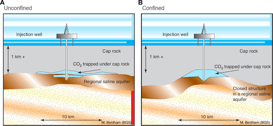
FIGURE 6. Conceptual representation of geologic CO2 storage in open (A) and closed (B) saline aquifers (Bentham and Kirby, 2005).
Due to their ubiquitous occurrence in sedimentary basins on all continents, saline formations/aquifers have the greatest potential for large-scale carbon storage (Bentham and Kirby, 2005; Michael et al., 2010; Shukla Potdar and Vishal, 2016; Ringrose et al., 2021). The reservoir must be at least approximately 800 m deep so that the pressure at these depths causes a phase transition of CO2 from gas to a supercritical fluid with much higher density, illustrated in Figure 7 (Ringrose et al., 2021). Storing dense CO2 in this manner decreases its volume many times (CO2CRC, 2021), thus dramatically increasing the storage capacity of a saline aquifer (and any other potential storage reservoir with pore space).
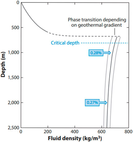
FIGURE 7. CO2 density versus depth for a geothermal gradient of 35°C/km (± 2°C/km; gray lines) and hydrostatic pore pressure. CO2 transitions from gas to a supercritical fluid between 550 m and 750 depths, depending on temperature. Blue boxes show the relative volume of CO2 at depth compared to surface volumes (Ringrose et al., 2021).
Several trapping mechanisms occur in saline formations some of which are common to other settings, such as depleted hydrocarbon reservoirs: (1) Structural and stratigraphic trapping, where CO2 exists as a continuous fluid and it can flow, (2) residual trapping, as non-connected, isolated CO2 pockets, (3) solubility trapping, which is synonymous with dissolution trapping, and (4) mineral trapping, which involves chemical reactions and the formation of carbonate minerals (Snæbjörnsdóttir et al., 2020). With time, CO2 can progress from structural/stratigraphic trapping all the way to mineral trapping thus progressively increasing the storage security. The time dependency of these four known trapping mechanisms is conceptually demonstrated in Figure 8. Timing and CO2 volumes associated with these mechanisms are uncertain.
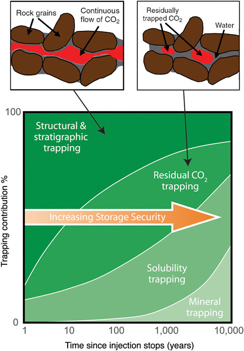
FIGURE 8. Conceptual representation of how the contribution of CO2 trapping mechanisms change with time when CO2 is injected as a supercritical fluid (Modified after IPCC, 2005; Garcia et al., 2010; Snæbjörnsdóttir et al., 2020).
The world’s first large-scale, industrial capture and offshore effort to store CO2 in a saline formation is the Sleipner project in the North Sea. Since 1996, Norwegian operator Equinor (FKA Statoil) has been injecting CO2 into the ∼200 m thick Utsira Sands at depths of 900–1000 m (Arts et al., 2004). The source of the CO2 is production of a condensate gas in the deeper Heimdal Formation (∼2500 m) with approximately 9% CO2 content. Due to a carbon tax in Norway, the operator and partners decided to sequester the CO2. An extensive geophysical and environmental monitoring program has been deployed. At the time, there were no monitoring guidelines or requirements imposed (storage and monitoring regulations in Norway became active in 2014), and so the operating companies opted for a large variety of methods with regular repeats and dense coverage. No CO2 leakage has been detected.
4D seismic (AKA time-lapse 3D seismic) and gravity monitoring were conducted to track the CO2 plume via velocity and density changes compared to the initially brine-filled reservoir (Furre et al., 2017). 3D seismic surveys were conducted in 1999, 2001, 2002, 2004, 2006, 2008, 2010, 2013, and 2016, and this provided an excellent dataset to seismically image the position and shape of the CO2 plume (See Figure 1 in Oudinot et al., 2017) (See Figure 2 in Furre et al., 2017).
High-precision gravity monitoring was conducted as well to provide an independent measurement of density changes. This effort confirmed the time-lapse seismic determined plume outline, and, within measurement uncertainty, that the amount of detected supercritical CO2 equals the injected amount (Furre et al., 2017).
CO2 injection scenarios or concepts often involve siliclastic reservoirs but many world-class reservoirs and aquifers are carbonates so CO2 interaction with limestone reservoir represents an uncertainty and opportunity to unlock additional potential in saline aquifer sequestration (Raza et al., 2020).
3.4 Geologic carbon storage in coal seams
Coal seams are dual porosity systems characterized by (1) matrix porosity, and (2) fracture (cleat) porosity (IPCC, 2005; Liu et al., 2018). This co-existence of matrix micropores and open fractures provides for very efficient storage mechanisms for adsorbing a variety of gases, including methane and CO2 (IPCC, 2005). Methane moves within and through coal by diffusion in the matrix and Darcy flow in the fractures (Kou et al., 2021). Storage options for CO2 in coal beds comprise injection into what is generally characterized as deep, unmineable coal seams and CO2-Enhanced Coal Bed Methane (ECBM).
Coal beds are classified as unmineable if they meet the following criteria: too thin, too deep, too unsafe for mining operations, too high in sulphur or mineral matter, too low in grade (Bachu, 2007). It is important to understand that the criteria used to determine a viable depth range for unmineable coal beds that are, however, suitable for CO2 storage are not consistently defined. For instance, candidate coal beds should be deeper than any groundwater aquifers and deeper than any coal beds that are mined in the future. A depth window is defined locally in central and southern Alberta between a ceiling, based on water well depths, of 300 m and, based on the CO2 phase transition from gas to supercritical fluid, a floor of 800–900 m (Bachu, 2007). Similar to CO2-EOR applied in oil fields, geological carbon storage in coal seams is often seen as a win-win technology, because two benefits are simultaneously realized: (1) increase the production of coal bed methane, and (2) leave CO2 behind in the pore space for permanent sequestration. CO2-ECBM works by gas exchange in the coal matrix. When methane is produced by thermal maturation, it adsorbs onto surfaces in the coal matrix. CO2 has greater adsorption capacity in coal compared to methane. Therefore, if CO2 is injected into coal, it causes desorption of methane, which is released into the cleats and subsequently replaced in the matrix by CO2.
Proof-of-concept of CO2-ECBM was achieved in 1972 through laboratory work which demonstrated removal of methane from crushed coal by streaming CO2 through it (Every and Dell’osso Jr., 1972). However, a recurring issue with injecting CO2 into coal beds is swelling of the matrix, reducing the cleat aperture, thereby significantly reducing the permeability for methane flow in the cleat network (Oudinot et al., 2017). N2 has lower adsorption capacity than methane. As a result, N2 has the opposite effect on coal matrix volume: the coal matrix shrinks, cleat aperture is opened, and permeability increased. Hence, one way to improve the efficiency of CO2-ECBM is to explore the amount, timing, and frequency of N2 injection before CO2 injection, or in an alternating fashion.
Priming coal with certain chemicals can potentially result in much greater CO2 storage. For instance, the substance methyl orange can increase the CO2 adsorption potential of coal nearly ten times (Abid et al., 2021). Methyl orange is a classic dye used in a number of industries, such as textile, paper, rubber, cosmetic, wool, and nylon. This substance is often released into the hydrosphere as a pollutant. Making use of it as an adsorption catalyzer for CO2 in coal could realize two benefits, namely sequestering CO2 in coal as well as safely disposing methyl orange (Abid et al., 2021).
3.5 In-situ and ex-situ carbon mineralization
Conceived as novel concepts in the 1990s, mineral trapping of CO2 (Figure 8) via artificially induced carbon mineralization is an accelerated form of naturally occurring chemical fixation of CO2 in the form of solid carbonate minerals (Seifritz, 1990; Lackner et al., 1995; Kelemen et al., 2019). During this process, chemical reactions form calcium, magnesium, and iron carbonates. The resulting minerals are identical to the naturally occurring equivalents, which have been stable for millions of years (Lackner et al., 1995).
The geochemistry of mineral carbonation is well understood and comprises the following general steps (Aradóttir et al., 2011):
Step 1:. Dissolution of CO2 in water forms carbonic acid.
Step 2:. Carbonic acid dissociates into bicarbonate and carbonate according to:
Step 3:. Dissolution of cations takes place when Ca-, Mg-, and Fe-bearing silicate minerals come in contact with this acidic fluid.
Step 4:. The free cations Ca, Mg, and Fe react with carbonate and precipitate carbonate minerals according to:
Ca-, Mg-, and Fe-bearing silicate minerals, such as plagioclase, pyroxene, and olivine, are found in mafic and ultramafic rocks, such as basalt and peridotite, and they are present in large quantities in pulverized form in mine tailings and other industrial waste products. Currently, in-situ and ex-situ mineral carbonation operations employ injection of CO2 (dissolved in water or as liquid or supercritical fluid) into basalt, and exposing ground reactive rock to CO2 in a gas stream, respectively (Snæbjörnsdóttir et al., 2020). Creating new carbonate minerals using these techniques essentially mimics natural weathering, albeit at a faster rate under ideal circumstances when reactions rates can be accelerated (Kelemen et al., 2019; McQueen et al., 2020).
3.5.1 In-situ carbon mineralization
In-situ carbon mineralization takes place in the subsurface by injection of CO2 into compositionally and structurally suitable rocks. As described in the previous section, CO2 reacts with formation water and any divalent cations that are present to form stable carbonate minerals.
Two field studies were undertaken to demonstrate the feasibility of in-situ carbon mineralization in basalt: The CarbFix project in Iceland (a combined industrial-academic pilot project), which is still active, and the smaller-scale Wallula pilot project in Washington, United States, during which 1,000 tons of CO2 were injected in 2013 (Snæbjörnsdóttir et al., 2020). The CarbFix method utilizes the dissolution of CO2 in water during injection, whereas the Wallula project exercises injection of pressurized, liquid CO2 (Snæbjörnsdóttir et al., 2020). The CarbFix project demonstrated that in-situ carbon mineralization is technically feasible and also practical at operational timescales. For example, more than 95% of the injected CO2 was mineralized in less than 2 years (Matter et al., 2016). The CO2 utilized in the CarbFix project is a byproduct of geothermal water production at the Hellisheiði geothermal power plant (Gunnarsson et al., 2018). The Carbfix project maintains a website showing the daily as well as the total cumulative volumes of CO2 injected (Carbfix, 2021). As of 10/6/2021, roughly 72,500 tons of CO2 have been injected since 2014. In contrast, the Wallula pilot was a much smaller demonstration project. Over a 2 months period in 2013, approximately 1,000 tons of CO2 were injected into brecciated basalt capped by basalt (White et al., 2020). A blend of hydrological tests and numerical modeling indicated that about 60% of the injected CO2 was mineralized within 2 years (White et al., 2020).
In-situ carbon mineralization has the potential for widespread upscaling, for example in regions with buried basaltic volcanoes and lava fields (Holford et al., 2021). However, temperatures exceeding 250°C in geothermal fields may potentially induce decarbonation reactions at depths greater than 1300 m (Clark et al., 2020). Effective monitoring techniques and water requirements are also uncertain (Raza et al., 2022).
Figure 8 illustrates that in-situ carbon mineralization (mineral trapping) likely occurs associated with other carbon storage methods as well, such as in saline aquifers, as long as the rock composition allows for the above quoted chemical reactions to occur. Note however, that meaningful contributions from this process do not occur until hundreds to thousands of years have passed since initial injection as a supercritical fluid. Hence, it is difficult, if not impossible, to quantify and control the exact contributions of in-situ mineralization as one contributor amongst others in a carbon storage project. On the other hand, the CarbFix and Wallula projects mentioned above demonstrate that targeted CO2 injection in basalt achieve predictable mineralization on short timescales, on the order of years, thus making such projects very viable from planning and operational perspectives.
3.5.2 Ex-situ carbon mineralization
By contrast to subsurface operation of in-situ carbon mineralization, ex-situ carbonation mineralization is run above ground. This method involves the reaction of a suitable feedstock (such as fly ash, waste from the steel and iron industries, ground reactive rock, and mine tailings) with CO2 in a gas stream (Snæbjörnsdóttir et al., 2020). The resulting stable carbonate minerals are disposed subsequently. Owing to the much higher cost of ex-situ compared to in-situ carbon mineralization associated with grinding and transporting the feedstock (Kelemen et al., 2019; Snæbjörnsdóttir et al., 2020), this technology is not widely used currently. Nonetheless, due to the high technical viability, there likely is large potential for this technology to be employed in the future (Picot et al., 2011). In addition, technologies beyond CO2 gas floods are being developed (Yadav and Mehra, 2021), and there is even potential for repeat direct air capture of CO2 using ex-situ mineralization of magnesite (McQueen et al., 2020). Ex-situ carbon mineralization may be particularly applicable in the mining industry, where large volumes of rocks are crushed and pulverized. For example, kimberlite mines yield enormous amounts of fine-grained tailings from processing ultramafic rocks that are composed of silicate minerals, such as serpentine, olivine, brucite, and smectite. Recent work shows that ex-situ carbonation of 4.7–24.0 wt% of annually processed kimberlite could offset 100% of carbon dioxide equivalent emissions of the mines investigated (Mervine et al., 2018).
One potential disadvantage of permanently locking up CO2 in carbonate minerals is that it cannot be retrieved from the sequestration site, should there be a profitable market for CO2 as a commodity in the future. The energy required for reversing the mineralization process and releasing CO2 again is substantial (Lackner et al., 1995) and would likely defeat the purpose of removing it from the atmosphere.
4 Analysis of geologic carbon storage sites
The principal purpose of structural geological and geomechanical characterization of potential CO2 storage sites is to ensure hydraulic integrity of the geological formations into which CO2 is injected and the ones around it (Hawkes et al., 2005). This can be achieved by describing the structural geometry, for example through identifying potential leak points, spill points, as well as potential pathways along which CO2 may escape to undesired formations and/or the atmosphere, and establishing the hydrodynamic conditions in the reservoir (Larkin, 2010). In addition, CO2 injection increases the pore pressure in the reservoir, which alters the state of stress in the near and far fields, which can trigger fault reactivation, create new fractures, and thus induce seismicity (Burghardt, 2017).
A useful way to help illustrate the concept of structural geometry for laypersons is to conduct a thought experiment with a hypothetical marble run (Figure 9). Imagine placing a marble on the top ramp and trying to predict which path the marble will take until it ultimately ends up on the bottom ramp (Figure 9A). A special condition in this marble run is a thin paper membrane on the third ramp (from top) that cannot hold the weight of the marble. The marble will break the membrane and drop down to the next lower ramp. This represents a transmissibility barrier. Now turn the marble run upside down (Figure 9B). Repeat the thought experiment and imagine that the marble is buoyant so that it will move upwards. The upside-down marble run is an excellent analog for petroleum and CO2 trap analysis. Now imagine that the marble represents a buoyant hydrocarbon or CO2 fluid molecule. Forecasting the upward path of the marble is akin to predicting the migration pathway of a fluid in the subsurface. The migration pathway can be along permeable sandstone or limestone units that are separated by impermeable shale or evaporite seal units (analogous to the black ramps in this experiment). Faults may juxtapose either sandstone/limestone on seal creating a sealing configuration, or sandstone/limestone on itself or another sandstone/limestone unit, creating a leaking configuration. The paper membrane in Figure 9B may represent a leak point in the subsurface shaped by fault juxtaposition. Upward flow will continue until an ultimate geometric trapping configuration is encountered.
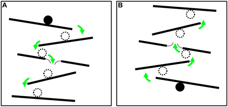
FIGURE 9. Schematic illustration of a hypothetical marble run. Green arrows show the path the marble will take when placed on the top ramp. (A). Right-side up. A thin paper membrane on the third ramp represents a potential leak point if the marble weighs more than the membrane can hold. (B). Upside-down marble run representing the concept of trap analysis for a buoyant fluid, such as petroleum or CO2.
A number of potential leak points can exist in geological CO2 storage sites (Figure 10). For example, faults can juxtapose reservoir on reservoir or act as fluid conduits themselves, hydraulic fractures can affect and compromise the seal above a storage reservoir, and there may be cement issues in a well connecting two adjacent or stacked reservoirs (Hawkes et al., 2005). These and similar issues can cause inadvertent CO2 migration from an intended storage reservoir to an unintended porous formation, such as an aquifer, and ultimately to the surface and into the atmosphere.
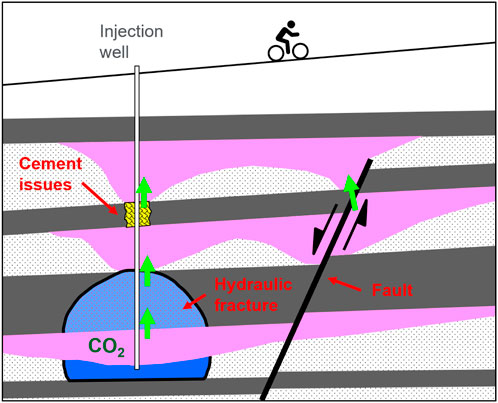
FIGURE 10. Schematic illustration of possible CO2 leakage pathways. Potential CO2 migration indicated with green arrows. Modified from original publication (Hawkes et al., 2005).
When CO2 and formation water coexist as separate phases during structural, stratigraphic, or residual trapping in a geologic formation (Figure 8), capillary processes determine the column height of the CO2 body (Ringrose, 2020). The physics of capillary trapping is well understood and the height of a gas column that can be held against gravity by the capillary entry pressure of the seal rock can be calculated according to (Berg, 1975):
where rcap and rres are the pore throat radii in the cap rock and reservoir, respectively, γ is the interfacial tension, θ is the fluid contact angle, and ρw and ρg are the water and gas densities, respectively. CO2 column height is one important input for determining the CO2 storage volume of a potential site. As can be seen from Eq. 6, a large difference between the pore throat radii of the cap rock and reservoir and a small density contrast between water and gas yield a large gas column, whereas a small difference in pore throat radii and a large density contrast achieve a small column.
The risk for fault reactivation can be assessed using simple Mohr-Coulomb theory. The slip tendency Ts of an existing fault in the subsurface can be calculated if the shear and normal stresses on the fault plane, τ and σn, as well as the pore pressure, Pf, are known, according to (Streit and Hillis, 2004):
Eqs. 6, 7 are useful for determining CO2 column height and fault slip tendency for screening purposes and to help identify and rank the most viable and lowest risk candidates among a portfolio of potential storage sites.
It is important to understand that the in-situ stress state exerts a first-order control on the geomechanical behavior of rocks during CO2 injection. While the approaches summarized above provide first-order answers, they are limited to one-dimensional analysis and assume spatially homogeneous as well as uniform rock properties and behaviors. Quasi-one-dimensional simplifications, as often used in the petroleum industry, are inaccurate (Burghardt, 2017). Stress is a three-dimensional tensor, and thus characterizing a potential CO2 storage site more comprehensively and accurately requires three-dimensional geomechanical modeling. Three-dimensional geomechanical modeling provides the ability to incorporate fault plane orientation, in-situ stress orientations and magnitudes, pore pressure, spatial variation in reservoir and seal parameters, and wellbores in the investigation. Seamless integration of geomechanical modeling with reservoir modeling and simulation is highly desirable to capture the production history as well as the spatial distribution of porosity and permeability.
Inventorying, screening, and selecting a site in the first place is a portfolio development and optimization process akin to any other kind of resource exploration. However, carbon sequestration is not a mature line of subsurface engineering and there are few documented cases where a full cycle of exploration through delineation and project execution has been achieved. There have been a number of portfolio development cases (Bentham et al., 2014; Gruson et al., 2015). Although free from the constraints of hydrocarbon source kitchen and migration pathways that are considerations in hydrocarbon portfolio development, there are several additional technical criteria relevant to CO2 site portfolios. These criteria include acceptable depth range, proximity to other subsurface management projects such as hydrocarbon production, potable water aquifers, civil infrastructure, the CO2 sources, as well as potential reservoir size, effectiveness and uncertainty. Various criteria and screening methodologies are available in guideline documents (ISO, 2017; NETL, 2017; Frailey et al., 2018) but these ultimately have to be tailored to local geopolitical and commercial requirements.
Large-scale CO2 sequestration projects carry significant pressure management requirements due to the volumes in question, especially in the option of CO2 solution injection (Bryant, 2013; Pool et al., 2013). These can be ameliorated to some degree by choosing to inject into depleted hydrocarbon fields (Jenkins et al., 2012), areas of natural underpressure such as actively deglaciating regions (Bekele and Rostron, 2003), or unconfined aquifers (Sigfusson et al., 2015). The storage volume potential of a prospective CO2 sequestration site is difficult to estimate due to the absence of storage efficiency information in large-scale projects, and various estimating methodologies are available (De Silva and Ranjith, 2012).
5 Discussion
One important aspect of carbon management to mitigate climate change is geologic carbon storage. Five methods of GCS have been validated through several demonstration and pilot projects around the world: (1) storage in depleted oil and gas fields, (2) use of CO2 in enhanced hydrocarbon recovery, (3) storage in saline formations/aquifers, (4) injection into deep unmineable coal seams, and (5) in-situ/ex-situ carbon mineralization. The role of geoscience in carbon storage lies in bringing forward and characterizing prospective CO2 storage sites. Once a site has been identified, basic subsurface work inevitably entails: (1) reservoir characterization to estimate pore volume and flow behavior, (2) describing the structural geometry to flag potential leak zones, spill points, and fluid pathways along which CO2 may escape from the intended storage formation, and (3) seal characterization and reservoir pressure to ensure hydraulic integrity.
Selection of any of these five methods requires storage site screening and feasibility studies to ensure project viability. Elaborating on these efforts is beyond the scope of this article. It is useful, however, to distinguish between CO2 storage options from a site selection and project management perspective as well as considering trapping mechanisms, which are subject to naturally occurring fundamental chemical and geomechanical processes. Once a storage site has been selected for one of the five options we summarized, multiple trapping mechanisms may occur simultaneously or sequentially over time (Figure 8). For example, carbon storage in a saline aquifer or a depleted hydrocarbon field typically begins by injecting CO2 as a supercritical fluid into a suitable subsurface containment. Initially, structural and stratigraphic trapping of CO2 as a single-phase fluid occurs as the dominant trapping mechanism. Over time, residual and solubility trapping start contributing as well, and after hundreds to thousands of years, mineral trapping may set in, permanently locking CO2 in the subsurface by producing new carbon minerals. Not surprisingly, some trapping mechanisms can occur during multiple storage methods as exemplified by in-situ carbon mineralization/mineral trapping. However, practical and operational factors during project execution would obviously favor in-situ mineralization in suitably mafic rocks and environments where reaction rates are fast (on the order of years) rather than relying on mineral trapping as a minor contributor in mainly subsurface CO2 fluid storage with considerable uncertainties regarding the timing and amounts of in-situ carbon mineralization.
Another way to think about temporal transitions amongst different carbon storage methods is to conduct a simple thought experiment and track a single CO2 molecule which transitions from one storage option to another. For example, a CO2 molecule may start off in an enhanced oil or gas recovery operation. At the end of the field life, the CO2 molecule is trapped in a depleted oil field. At some point, it will dissolve in the formation brine and ultimately, depending on the availability of Fe and Mg cations, even react to form carbonate minerals. This thought experiment demonstrates that the five storage options summarized above are not necessarily fully separate and that transitions amongst them are likely to occur.
Author contributions
MA—Lead author contributing to all sections SS—Section on characteristic of storage sites, editing RG—Site analysis section and aquifers.
Acknowledgments
Two reviewers are acknowledged for constructive reviews which helped improve our article. We thank Saudi Aramco and Aramco Americas for permission to publish this article.
Conflict of interest
MA and RG were employed by the company of Aramco Americas, Houston Research Center. SS was employed by the company of Saudi Aramco.
Publisher’s note
All claims expressed in this article are solely those of the authors and do not necessarily represent those of their affiliated organizations, or those of the publisher, the editors and the reviewers. Any product that may be evaluated in this article, or claim that may be made by its manufacturer, is not guaranteed or endorsed by the publisher.
References
Abid, H. R., Iglauer, S., Al-Yaseri, A., and Keshavarz, A. (2021). Drastic enhancement of CO2 adsorption capacity by negatively charged sub-bituminous coal. Energy 233, 120924. doi:10.1016/j.energy.2021.120924
Aradóttir, E. S. P., Sigurdardóttir, H., Sigfússon, B., and Gunnlaugsson, E. (2011). CarbFix: A CCS pilot project imitating and accelerating natural CO2 sequestration. Greenh. Gases Sci. Technol. 1, 105–118. doi:10.1002/ghg.18
Arts, R., Eiken, O., Chadwick, A., Zweigel, P., Van, M B., and Kirby, G. (2004). “Seismic monitoring at the Sleipner underground CO2 storage site (North Sea),” in Geologic storage of carbon dioxide. Editors S. J. BAINES, and R. H. WORDEN (London: Geologic Society Special Publications).
Bachu, S. (2007). Carbon dioxide storage capacity in uneconomic coal beds in Alberta, Canada: Methodology, potential and site identification. Int. J. Greenh. Gas Control 1, 374–385. doi:10.1016/s1750-5836(07)00070-9
Bansal, P. (2012). A review–status of CO2 as a low temperature refrigerant: Fundamentals and R&D opportunities. Applied Thermal Engineering 41, 18–29.
Bekele, E. B., and Rostron, B. J. (2003). Fluid pressure implications of erosional unloading, basin hydrodynamics and glaciation in the Alberta Basin, Western Canada. J. Geochem. Explor. 78-79, 143–147. doi:10.1016/s0375-6742(03)00148-1
Bentham, M., and Kirby, G. A. (2005). CO2 storage in saline aquifers. Oil Gas Sci. Technol. 60, 559–567. doi:10.2516/ogst:2005038
Bentham, M., Mallows, T., Lowndes, J., and Green, A. (2014). CO2 STORage Evaluation Database (CO2 Stored). The UK's online storage atlas. Energy Procedia 63, 5103–5113. doi:10.1016/j.egypro.2014.11.540
Berg, R. R. (1975). Capillary pressures in stratigraphic traps. Am. Assoc. Petroleum Geol. Bull. 59, 939–956.
Bryant, S. (2013). CO2 sequestration at material rates: Inherent limits and engineering solutions. Energy Procedia 37, 2684–2693. doi:10.1016/j.egypro.2013.06.153
Cappa, J. A., and Rice, D. D. (1995). Carbon dioxide in Mississippian rocks of the Paradox Basin and adjacent areas Colorado Utah New Mexico Arizona. Denver, CO: U.S. G.P.O.; For sale by U.S. Geological Survey, Information Services, 30. doi:10.3133/b00H
CARBFIX (2021). Carbfix – we turn CO2 into stone. [Online]. Available at: www.carbfix.com/(Accessed October 14, 2021).
Clark, D. E., Oelkers, E. H., Gunnarsson, I., Sigfússon, B., Snæbjörnsdóttir, S. Ó., Aradóttir, E. S., et al. (2020). CarbFix2: CO2 and H2S mineralization during 3.5 years of continuous injection into basaltic rocks at more than 250°C. Geochimica Cosmochimica Acta 279, 45–66. doi:10.1016/j.gca.2020.03.039
Cook, P. (2014). Geologically storing carbon: Learning from the Otway project experience. Melbourne: CSIRO Publishing.
Davies, R. J., Almond, S., Ward, R. S., Jackson, R. B., Adams, C., Worrall, F., et al. (2014). Oil and gas wells and their integrity: Implications for shale and unconventional resource exploitation. Mar. Petroleum Geol. 56, 239–254. doi:10.1016/j.marpetgeo.2014.03.001
De Silva, P. N. K., and Ranjith, P. G. (2012). A study of methodologies for CO2 storage capacity estimation of saline aquifers. Fuel 93, 13–27. doi:10.1016/j.fuel.2011.07.004
Erikson, J. (2020). International CCUS development efforts. WIEB + NARUC CCUS workshop series. Global CCS Institute.
Every, R. L., and Dell’Osso, J. R. L. (1972). A new technique for the removal of methane from coal. Cim. Bull. 65, 143–150.
Frailey, S., Koperna, G., and Tucker, O. (2018). “The CO2 storage resources management system (SRMS): Toward a common approach to classifying, categorizing, and quantifying storage resources,” in 14th Greenhouse Gas Control Technologies Conference Melbourne, 21–26.
Friedlingstein, P., Jones, M. W., O'Sullivan, M., Andrew, R. M., Bakker, D. C. E., Hauck, J., et al. (2022). Global carbon budget 2021. Earth Syst. Sci. Data 14, 1917–2005. doi:10.5194/essd-14-1917-2022
Furre, A.-K., Eiken, O., Alnes, H., Vevatne, J. N., and Kiær, A. F. (2017). 20 Years of monitoring CO2-injection at sleipner. Energy Procedia 114, 3916–3926. doi:10.1016/j.egypro.2017.03.1523
Garcia, S., Kaminska, S., and Mercedes Maroto-Valer, M. (2010). Underground carbon dioxide storage in saline formations. Proc. Institution Civ. Eng. – Waste Resour. Manag. 163, 77–88. doi:10.1680/warm.2010.163.2.77
Gerling, C. R. (1983). “McElmo dome Leadville carbon dioxide field, Colorado,– in Oil and gas fields of the four corners area. Editor J. E. Fassett (Four Corners Geological Society), 3, 735–739.
Gruson, J. F., Serbutoviez, S., Delprat-Jannaud, F., Akhurst, M., Nielsen, C., Dalhoff, F., et al. (2015). Techno-economic assessment of four CO2Storage sites. Oil Gas Sci. Technol. – Revue d’IFP Energies nouvelles 70, 753–766. doi:10.2516/ogst/2014057
Gunnarsson, I., Aradóttir, E. S., Oelkers, E. H., Clark, D. E., Arnarson, M. Þ., Sigfússon, B., et al. (2018). The rapid and cost-effective capture and subsurface mineral storage of carbon and sulfur at the CarbFix2 site. Int. J. Greenh. Gas Control 79, 117–126. doi:10.1016/j.ijggc.2018.08.014
Hawkes, C. D., McLellan, P. J., and Bachu, S. (2005). Geomechanical factors affecting geological storage of CO2 in depleted oil and gas reservoirs. J. Can. Petroleum Technol. 44. doi:10.2118/05-10-05
Holford, S., Schofield, N., Bunch, M., Bischoff, A., and Swierczek, E. (2021). Storing CO2 in buried volcanoes. APPEA J. 61, 626. doi:10.1071/aj20056
Holloway, S., Pearce, J. M., Hards, V. L., Ohsumi, T., and Gale, J. (2007). Natural emissions of CO2 from the geosphere and their bearing on the geological storage of carbon dioxide. Energy 32, 1194–1201. doi:10.1016/j.energy.2006.09.001
Holloway, S., Pearce, J. M., Ohsumi, T., and Hards, V. L. (2005). A review of natural CO2 occurrences and their relevance to CO2 storage. British Geological Survey, Sustainable Energy and Geophysics Programme, External Report CR/05/104117
Huang, Q., Liu, Z., Zhou, Y., Zhang, D., and Qang, F. (2014). Study on mechanisms of CO2 BLEVE based on the cusp-catastrophe model. Energy Procedia 61, 1343–1347. doi:10.1016/j.egypro.2014.12.123
ISO (2017). Carbon dioxide capture, transportation and geological storage - geological storage. Switzerland: ISO Copyright Office. Reference Number ISO 27914:2017(E).
IPCC (2021). “Climate change 2021: The physical science basis. Contribution of working group I to the sixth assessment report of the intergovernmental panel on climate change,” in MASSON-DELMOTTE, V. Editors P. ZHAI, A. PIRANI, S. L. CONNORS, C. PÉAN, S. BERGER, N. CAUDet al.
IPCC (2005). “Underground geological storage,” in IPCC Special Report on Carbon Dioxide Capture and Storage, prepared by Working Group III of the Intergovernmental Panel on Climate Change. Editors B. METZ, O. DAVIDSON, H. C. DE CONINCK, M. LOOS, and L. A. MEYER (Cambridge, United Kingdom: Cambridge University Press), 195–276.
Jenkins, C. R., Cook, P. J., Ennis-King, J., Undershultz, J., Boreham, C., Dance, T., et al. (2012). Safe storage and effective monitoring of CO2 in depleted gas fields. Proceedings of the National Academy of Sciences. 109, E35–E41.
Kelemen, P., Benson, S. M., Pilorgé, H., Psarras, P., and Wilcox, J. (2019). An overview of the status and challenges of CO2 storage in minerals and geological formations. Front. Clim. 1. doi:10.3389/fclim.2019.00009
Kiran, R., Teodoriu, C., Dadmohammadi, Y., Nygaard, R., Wood, D., Mokhtari, M., et al. (2017). Identification and evaluation of well integrity and causes of failure of well integrity barriers (A review). J. Nat. Gas Sci. Eng. 45, 511–526. doi:10.1016/j.jngse.2017.05.009
Kokal, S., Sanni, M., and Alhashboul, A. (2016). “Design and implementation of the first CO2-EOR demonstration project in Saudi Arabia,” in Paper presented at the SPE Annual Technical Conference and Exhibition, Dubai, UAE. doi:10.2118/181729-MS
Kou, Z., Wang, T., Chen, Z., and Jiang, J. (2021). A fast and reliable methodology to evaluate maximum CO2 storage capacity of depleted coal seams: A case study. Energy. 231.
Lackner, K. S., Wendt, C. H., Butt, D. P., Joyce, J. R., E., L., and Sharp, D. H. (1995). Carbon dioxide disposal in carbonate minerals. Energy 20, 1153–1170. doi:10.1016/0360-5442(95)00071-n
Langston, M. V., Hoadley, S. F., and Young, D. N. (1988). “Definitive CO2 flooding response in the SACROC unit,” in Paper presented at the SPE enhanced oil recovery symposium (Tulsa, OK). doi:10.2118/17321-MS
Lankof, L., Urbańczyk, K., and Tarkowski, R. (2022). Assessment of the potential for underground hydrogen storage in salt domes. Renew. Sustain. Energy Rev. 160, 112309–112317. doi:10.1016/j.rser.2022.112309
Larkin, R. G. (2010). Hydrodynamic trapping of CO2 geosequestered in saline aquifers. 2010 SPE improved oil recovery symposium. Tulsa, Oklahoma: Society of Petroleum Engineers.
Lee, D. S. (2016). Carbon dioxide absorbers for food packaging applications. Trends food Sci. Technol. 57, 146–155. doi:10.1016/j.tifs.2016.09.014
Liu, S.-Y., Ren, B., Li, H.-Y., Yang, Y.-Z., Wang, Z.-Q., Wang, B., et al. (2022). CO2 storage with enhanced gas recovery (CSEGR): A review of experimental and numerical studies. Petroleum Sci. 19, 594–607. doi:10.1016/j.petsci.2021.12.009
Liu, S., Sang, S., Ma, J., Wang, X., Du, Y., and Wang, T. (2018). Three-dimensional digitalization modeling characterization of pores in high-rank coal in the southern Qinshui basin. Geosciences J. 23, 175–188.
Matos, C. R., Carneiro, J. F., and Silva, P. P. (2019). Overview of large-scale underground energy storage technologies for integration of renewable energies and criteria for reservoir identification. J. Energy Storage 21, 241–258. doi:10.1016/j.est.2018.11.023
Matter, J. M., Stute, M., Snaebjornsdottir, S. O., Oelkers, E. H., Gislason, S. R., Aradottir, E. S., et al. (2016). Rapid carbon mineralization for permanent disposal of anthropogenic carbon dioxide emissions. Science 352, 1312–1314. doi:10.1126/science.aad8132
Mcqueen, N., Kelemen, P., Dipple, G., Renforth, P., and Wilcox, J. (2020). Ambient weathering of magnesium oxide for CO2 removal from air. Nat. Commun. 11, 3299. doi:10.1038/s41467-020-16510-3
Mervine, E. M., Wilson, S. A., Power, I. M., Dipple, G. M., Turvey, C. C., Hamilton, J. L., et al. (2018). Potential for offsetting diamond mine carbon emissions through mineral carbonation of processed kimberlite: An assessment of De Beers mine sites in south Africa and Canada. Mineralogy Petrology 112, 755–765. doi:10.1007/s00710-018-0589-4
Michael, K., Golab, A., Shulakova, V., Ennis-King, J., Allinson, G., Sharma, S., et al. (2010). Geological storage of CO2 in saline aquifers—a review of the experience from existing storage operations. Int. J. Greenh. Gas Control 4, 659–667. doi:10.1016/j.ijggc.2009.12.011
Miocic, J. M., Gilfillan, S. M. V., Roberts, J. J., Edlmann, K., Mcdermott, C. I., and Haszeldine, R. S. (2016). Controls on CO2 storage security in natural reservoirs and implications for CO2 storage site selection. Int. J. Greenh. Gas Control 51, 118–125. doi:10.1016/j.ijggc.2016.05.019
NETL (2010). Carbon dioxide enhanced oil recovery. U.S. Department of Energy, National Energy Technology Laboratory. Available at: https://www.netl.doe.gov/sites/default/files/netl-file/co2_eor_primer.pdf
NETL (2017). Best practices: Site screening, site selection, and site characterization for geologic storage projects. 2017 Revised Edition ed. U.S. Department of Energy, Office of Fossil Energy. DOE/NETL-2017/1844
Nuñez-López, V., Gil-Egui, R., Hosseininoosheri, P., Hovorka, S. D., and Lake, L. W. (2019). Final report: Carbon life cycle analysis of CO2-EOR for net carbon negative oil (NCNO) classification. The University of Texas at Austin, SUBMITTED TO U.S. Department of Energy, National Energy Technology Laboratory.
Oudinot, A. Y., Riestenberg, D. E., and Koperna, G. J. (2017). Enhanced gas recovery and CO2 storage in coal bed methane reservoirs with N2 Co-injection. Energy Procedia 114, 5356–5376. doi:10.1016/j.egypro.2017.03.1662
Picot, J. C., Cassard, D., Maldan, F., Greffié, C., and Bodénan, F. (2011). Worldwide potential for ex-situ mineral carbonation. Energy Procedia 4, 2971–2977. doi:10.1016/j.egypro.2011.02.206
Pool, M., Carrera, J., Vilarrasa, V., Silva, O., and Ayora, C. (2013). Dynamics and design of systems for geological storage of dissolved CO2. Adv. Water Resour. 62, 533–542. doi:10.1016/j.advwatres.2013.10.001
Preston, C., Monea, M., Jazrawi, W., Brown, K., Whittaker, S., White, D., et al. (2005). IEA GHG Weyburn CO2 monitoring and storage project. Fuel Processing Technology 86 (14–15), 1547–1568.
Prinet, C., Thibeau, S., Lescanne, M., and Monne, J. (2013). Lacq-Rousse CO2 capture and storage demonstration pilot: Lessons learnt from two and a half years monitoring. Energy Procedia 37, 3610–3620. doi:10.1016/j.egypro.2013.06.254
Raza, A., Gholami, R., and Sarmadivaleh, M. (2020). Feasibility of limestone reservoirs as a carbon dioxide storage site: An experimental study. AAPG Bull. 103, 83–96. doi:10.1306/04241918124
Raza, A., Glatz, G., Gholami, R., Mahmoud, M., and Alafnan, S. (2022). Carbon mineralization and geological storage of CO2 in basalt: Mechanisms and technical challenges. Earth-Science Rev. 229, 104036. doi:10.1016/j.earscirev.2022.104036
Ringrose, P. (2020). How to store CO2 underground: Insights from early-mover CCS projects. Springer.
Ringrose, P. S., Furre, A. K., Gilfillan, S. M. V., Krevor, S., Landro, M., Leslie, R., et al. (2021). Storage of carbon dioxide in saline aquifers: Physicochemical processes, key constraints, and scale-up potential. Annu. Rev. Chem. Biomol. Eng. 12, 471–494. doi:10.1146/annurev-chembioeng-093020-091447
Roberts, J. J., and Stalker, L. (2020). What have we learnt about CO2 leakage from CO2 release field experiments, and what are the gaps for the future? Earth-Science Rev. 209, 102939. doi:10.1016/j.earscirev.2019.102939
Sacuta, N., Younbg, A., and Worth, K. (2015). International energy agency (IEA) greenhouse gas (GHG) – Weyburn – midale CO2 monitoring and storage project. Regina, Saskatchewan, Canada: Petroleum Technology Research Centre.
Sathaye, K., Hesse, M. A., Cassidy, M., and Stockli, D. F. (2014). Constraints on the magnitude and rate of CO2 dissolution at Bravo Dome natural gas field. Proc. Natl. Acad. Sci. 111, 15332–15337. doi:10.1073/pnas.1406076111
Shukla Potdar, R., and Vishal, V. (2016). “Trapping mechanism of CO2 storage in deep saline aquifers: Brief review,” in Geologic carbon sequestration. Editor V. Vishal, and T. Singh (Switzerland: Springer, Cham. doi:10.1007/978-3-319-27019-7_3
Sigfusson, B., Gislason, S. R., Matter, J. M., Stute, M., Gunnlaugsson, E., Gunnarsson, I., et al. (2015). Solving the carbon-dioxide buoyancy challenge: The design and field testing of a dissolved CO2 injection system. Int. J. Greenh. Gas Control 37, 213–219. doi:10.1016/j.ijggc.2015.02.022
Snæbjörnsdóttir, S. Ó., Sigfússon, B., Marieni, C., Goldberg, D., Gislason, S. R., and Oelkers, E. H. (2020). Carbon dioxide storage through mineral carbonation. Nat. Rev. Earth Environ. 1, 90–102. doi:10.1038/s43017-019-0011-8
Stevens, S. (2005). Natural CO2 fields as analogs for geologic C2 storage. doi:10.1016/B978-008044570-0/50129-X
Stevens, S. H., Schoell, M., Ballentine, C., and Hyman, D. M. (2005). Isotopic analysis of natural CO2 fields: How long has nature stored CO2 underground? Greenh. Gas. Control Technol. II, 1375–1379.
Stevens, S. H., and Tye, S. B. (2007). “Natural CO2 analogs for carbon sequestration,” in Prepared for: U.S. Department of Energy, National Energy Technology Laboratory (Arlington, VA: Advanced Resources International, Inc).
Streit, J. E., and Hillis, R. R. (2004). Estimating fault stability and sustainable fluid pressures for underground storage of CO2 in porous rock. Energy 29, 1445–1456. doi:10.1016/j.energy.2004.03.078
Stuart, I. A. (1991). “The rough gas storage field, blocks 47/3d, 47/8b, UK North Sea,”U. K. Oil Gas Fields, 25 Years Commem. Volume. Editor I. L. Abbotts (London: Geological SocietyThe Geological Society of London), Memoirs v.14, 477–484.
Thomaidis, N. D. (1978). Carbon dioxide exploration. Four Corners Geological Society 2011–Oil and Gas Fields of the Four Corners Area I–II, 4.
Underschultz, J., Boreham, C., Dance, T., Stalker, L., Freifeld, B., Kirste, D., et al. (2011). CO2 storage in a depleted gas field: An overview of the CO2CRC Otway Project and initial results. Int. J. Greenh. Gas Control 5, 922–932. doi:10.1016/j.ijggc.2011.02.009
Valluri, S., Claremboux, V., and Kawatra, S. (2022). Opportunities and challenges in CO2 utilization. J. Environ. Sci. 113, 322–344. doi:10.1016/j.jes.2021.05.043
Vandeweijer, V., Hofstee, C., Pelt Van, W., and Graven, H. (2020). “CO2 injection at K12-B, the final story,” in Proceedings of the 15th greenhouse gas control technologies conference, March 15–18, 2021. Available at SSRN: https://ssrn.com/abstract=3820865.
Wang, L., He, Y., Wang, Q., and Liu, M. (2020). Multiphase flow characteristics and EOR mechanism of immiscible CO2 water-alternating-gas injection after continuous CO2 injection: A micro-scale visual investigation. Fuel 282, 118689.
White, S. K., Spane, F. A., Schaef, H. T., Miller, Q. R. S., White, M. D., Horner, J. A., et al. (2020). Quantification of CO2 mineralization at the Wallula basalt pilot project. Environ. Sci. Technol. 54, 14609–14616. doi:10.1021/acs.est.0c05142
Whittaker, S. (2005) Geological characterization of the Weyburn field for geological storage of CO2: Summary of phase I results of the IEA GHG Weyburn CO2 monitoring and storage project,” in Summary of investigations 2005, Volume 1, Saskatchewan geological survey, Sask. Industry Resources, Misc. Rep. 2005-4.1, CD-ROM, Paper A-1, 6p
Woessner, W. W., and Poeter, E. P. (2020). Hydrogeologic properties of earth materials and principles of groundwater flow, 217. The Groundwater Project.
Yadav, S., and Mehra, A. (2021). A review on ex situ mineral carbonation. Environ. Sci. Pollut. Res. Int. 28, 12202–12231. doi:10.1007/s11356-020-12049-4
Zabel, V. H. (1955). Geology of McElmo Dome Montezuma County, Colorado. Four Corners Geological Society 2011 – Geology of Paradox, & San Juan Basins, Four Corner Field Conference, 132–136.
Zhang, M., and Bachu, S. (2011). Review of integrity of existing wells in relation to CO2 geological storage: What do we know? Int. J. Greenh. Gas Control 5, 826–840. doi:10.1016/j.ijggc.2010.11.006
Keywords: geologic carbon storage (GCS), carbon management, subsurface, geology, aquifers
Citation: Albertz M, Stewart SA and Goteti R (2023) Perspectives on geologic carbon storage. Front. Energy Res. 10:1071735. doi: 10.3389/fenrg.2022.1071735
Received: 16 October 2022; Accepted: 16 December 2022;
Published: 17 April 2023.
Edited by:
Yi Zhang, Dalian University of Technology, ChinaReviewed by:
Shuyang Liu, China University of Petroleum, ChinaVikram Vishal, Indian Institute of Technology Bombay, India
Copyright © 2023 Albertz, Stewart and Goteti. This is an open-access article distributed under the terms of the Creative Commons Attribution License (CC BY). The use, distribution or reproduction in other forums is permitted, provided the original author(s) and the copyright owner(s) are credited and that the original publication in this journal is cited, in accordance with accepted academic practice. No use, distribution or reproduction is permitted which does not comply with these terms.
*Correspondence: Rajesh Goteti, cmFqZXNoLmdvdGV0aUBhcmFtY29hbWVyaWNhcy5jb20=
†Present Address: Markus Albertz, Occidental Petroleum Corporation, The Woodlands, TX, United States