 Qingpeng Zeng
 Jin Zhu
 Xinming Guo1,2
 Qunhai Huo
 Jingyuan Yin
- 1Institute of Electrical Engineering, Chinese Academy of Sciences, Beijing, China
- 2University of Chinese Academy of Sciences, Beijing, China
A massive number of DC circuit breaker is usually necessary to be installed to protect HVDC grids from DC faults, this will lead to high capital costs because large number of expensive IGBT-in-series are used. In this paper, an interline hybrid circuit breaker is proposed by the combination of SCR string and a small number of H-bridge modules (SCR-IHCB). The proposed SCR-IHCB has the capacity of blocking DC fault of two adjacent lines respectively by sharing only one main breaker branch (MB) mainly composed of low-cost SCR string and H-bridge module instead of IGBT-in-series string. The interline current flow control function is also integrated. Hence it has advantages of simple and compact topology, economical design compared with typical IGBT based HCB solutions. The operation process of the proposed SCR-IHCB is discussed in detail, and the performance is verified by MATLAB Simulink simulation and scale-down prototype experiment.
1 Introduction
Nowadays, HVDC grids have attracted significant attention, due to its inherent advantages such as flexible control of active and reactive power, low loss, system redundancy, and power reliability (Flourentzou et al., 2009; Akhmatov et al., 2014). While the HVDC grid offers several advantages, its engineering application still faces several challenges, one of which is the DC fault handling. The DC circuit breakers (DCCBs) is considered as an essential technology to isolate the fault area and maintain normal operations of non-fault areas in HVDC grids. There are three main groups of DCCB: mechanical DCCBs (Shi et al., 2015; Lin et al., 2016), solid-state DCCBs (Corzine and Ashton, 2012; Sano and Takasaki, 2014; Chang et al., 2016; Keshavarzi et al., 2017; Li et al., 2019; Wang et al., 2019; Shu et al., 2020; Zhang et al., 2020; Xu et al., 2021), and hybrid DCCBs(HÄFNER and JACOBSON, 2011; Sander et al., 2018). The hybrid DCCBs combine the merits of mechanical DCCBs and solid-state DCCBs and therefore is considered as an acceptable solution in HVDC grids. The classic hybrid DCCB (HCB) topology contains a main breaker branch (MB), an energy absorption branch and a transfer branch, the transfer branch consists of an ultra-fast mechanical disconnector (UFD) in series with load current switch (LCS). There are two main groups of HCBs based on the different MB technical routes.
One of the technical routes is IGBT based MB, the classic IGBT-in-series based HCB has been proposed by ABB and successfully tested (HÄFNER and JACOBSON, 2011; Sander et al., 2018). The State Grid Corporation of China (SGCC) proposed a full-bridge modular based MB to avoid the problem of IGBT-in-series synchronization control and has been used in Zhangbei four-terminal MMC-HVDC (Jia et al., 2020; Jinkun et al., 2020.). In order to further reduce the system cost, some integration solutions are proposed, multi-line DC circuit breakers are integrated into one equipment to reduce the number of unidirectional MBs (Liu et al., 2017; Majumder et al., 2017; Mokhberdoran et al., 2018a; Kontos et al., 2018; Li and Wang, 2018; Xiao et al., 2020; Guo et al., 2021; Wang et al., 2022), another solution integrated HCBs and current flow controllers (CFCs) into one equipment is proposed in (Cwikowski et al., 2018; Mokhberdoran et al., 2018b; Zhu et al., 2022.) to reduce the system loss. But there are still some drawbacks to the hybrid DCCB topology as follows:
(1) Large number of series connected full-controlled semiconductors, such as IGBTs or IGCTs, in the main breaker increase the investment severely (Chen et al., 2018).
(2) In future, large DC grids fault currents may exceed the interruption capacity of IGBT under serious fault conditions. The parallel connection of IGBTs is needed but also introduces challenges in terms of construction cost (Dong et al., 2021).
Another technical route is SCR based MB, The SCR based MB has advantages of larger capacity, and lower price. Since the current conducted through the SCR need to reach a value below its threshold current during the turn-off process of SCR, apply a reverse voltage is one of the possible solutions to ensure fast transition from conducting to blocking. The most important issue when designing an SCR-based HCB is reliably to generate a reverse voltage on SCR during the turn-off process so as to make the current conducted through the SCR reach a value below its threshold current(Jamshidi Far and Jovcic, 2018).
Coupled inductors or Z-source schemes are used to generate the required reverse voltage on SCR during the turn-off process in (Ray et al., 2019). In those schemes, the transient fault current through capacitors is used to generate a reverse voltage on SCRs, hence those schemes can only be passively turned-off in the condition of the high current rising rate.
A thyristor full-bridge based HCB topology is proposed in (Guo et al., 2020), which can pre-charge the capacitor with DC system voltage, and the reverse voltage is generated by discharge process of pre-charged capacitor. The full-bridge structure is used to pre-charge the capacitor with dc system voltage and switch the fault current path, the use of large number of thyristor strings also increases the system cost.
A SCR-HCB with multiple branches is proposed by Alstom in (Grieshaber et al., 2015), the capacitance voltage difference of different branches is used to generate the required reverse voltage. The inductor is no longer needed, but if n branches are required for each HCB, 2n number of thyristor strings are required for two adjacent lines, which also increases the number of components in the whole DC grid system.
A DCCB topology combing many SCRs with a few IGBTs-in-series is proposed in (Shu et al., 2020). The required reverse voltage can be generated by controlled IGBT. However, each DCCB requires two additional IGBT strings, the utilization of the device needs to be increased in multi-terminal system.
In this paper, an interlink hybrid DC circuit breaker (IHCB) based on the concept of sharing only one SCR string MB between two lines is proposed (SCR-IHCB) to increase the utilization of the device. Only a few H-bridge submodule is embedded in to generate the required reverse voltage of SCR turn-off process, and the current flow controlling function is also integrated into the IHCB. No additional capacitor pre-charge circuits and inductors are required, the proposed solution can interrupt the short circuit current of two lines independently and control the current flow if necessary. Therefore, compared to the traditional DCCB/CFC schemes, the proposed topology is simple and economical.
2 Proposed topology
2.1 Basic structure of proposed SCR-IHCB
A novel IHCB is proposed in this paper and its detailed structure is shown in Figure 1. MB is composed of an anti-parallel SCR string and a H-bridge sub module, connecting line 12 and line 13. MOV2 is used to protect IGBTs in H-bridge sub module. The transfer branch consisting of LCS and UFD is installed on each line. C1 can be charged through T1 to the limiting voltage of MOV1 to block the fault current and absorb the residual energy of the system.
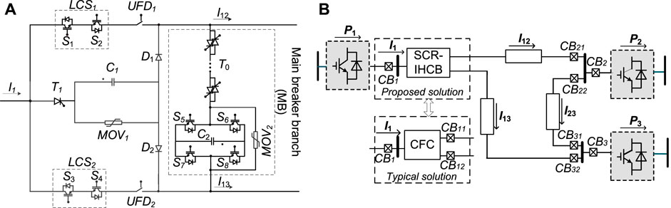
FIGURE 1. Proposed SCR-IHCB topology and installation position in system. (A) Proposed topology; (B) Three-terminal meshed HVDC system under study.
There are three modes of operation: normal operation without current flow controlling (bypass mode), normal operation with current flow controlling (CFC mode), fault current blocking mode. Obviously, higher system integration, lower volume and cost are achieved because only 1 MB mainly based on low-cost SCR string is used, and CFC function are integrated together.
2.2 Operation principles in different mode
2.2.1 Bypass mode
When the multiterminal HVDC (MT-HVDC) system is running normally, LCS1/LCS2 and UFD1/UFD2 are all conducted, the SCR string (T0) and H-bridge submodule are bypassed. There is no additional conduction loss and switching loss of semiconductor devices except LCS1/LCS2.
2.2.2 Current flow control mode
When the current flow needs to be adjusted, the proposed SCR-IHCB can work in CFC mode, the working principle is similar with other interline power flow controllers as shown in (Balasubramaniam et al., 2015; Sau-Bassols and Gomis-Bellmunt, 2017). The possible states concerning the available switches are summarized in Table 1.

TABLE 1. Switching states for CFC mode.
Where “1” represents the switch is ON and “0” represents the switch is OFF. In Figure 2, one pair of states (state1 and state 2 in Table 1)f of current flow scenarios (I12 and I13 are going out the SCR-IHCB and I1 is entering) are considered as an example. In order to transfer power from line13 to line 12, the CFC should switch continuously in state 1 and state 2 by alternating conduction of S1 and S3.
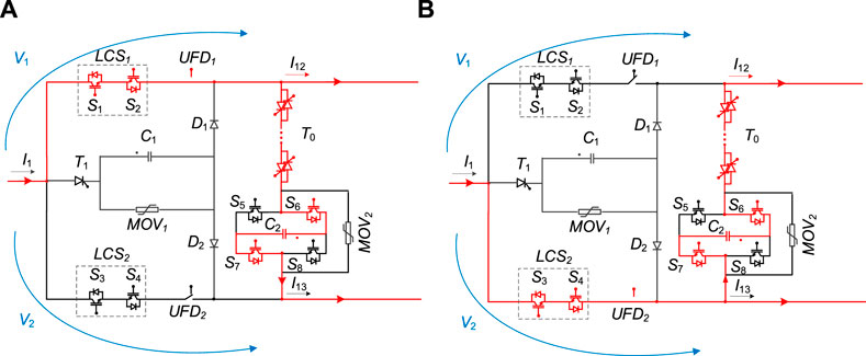
FIGURE 2. Operation stages of SCR-IHCB. (A) State 1; (B) State 2.
Below, the analytical analysis of the SCR-IHCB is performed for the pair of states (state 1 and state 2) presented before. Then, the analysis can be extended to the whole range of current configurations.
Taking state 1 as an example, capacitor C2 is charged by I13, which is equivalent to inserting a negative voltage in series with line 13. In state 2, capacitor C2 is discharged by I12, which is equivalent to inserting a positive voltage in series with line 12. Assuming D is the duty cycle of state 1. The average model of the three-terminal system with SCR-IHCB can be described as Figure 3.
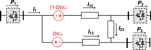
FIGURE 3. Average model of three-terminal DC grid with SCR-IHCB in current control mode.
2.2.3 Fault blocking mode
Take the DC short circuit fault of line12 when SCR-IHCB works in bypass mode as an example, the DC fault current blocking principle is given in Figure 4. Before the fault occurs, the load currents may flow through the low-loss transfer branches in bypass mode as shown in Figure 4A or in CFC mode such as shown in Figure 2.
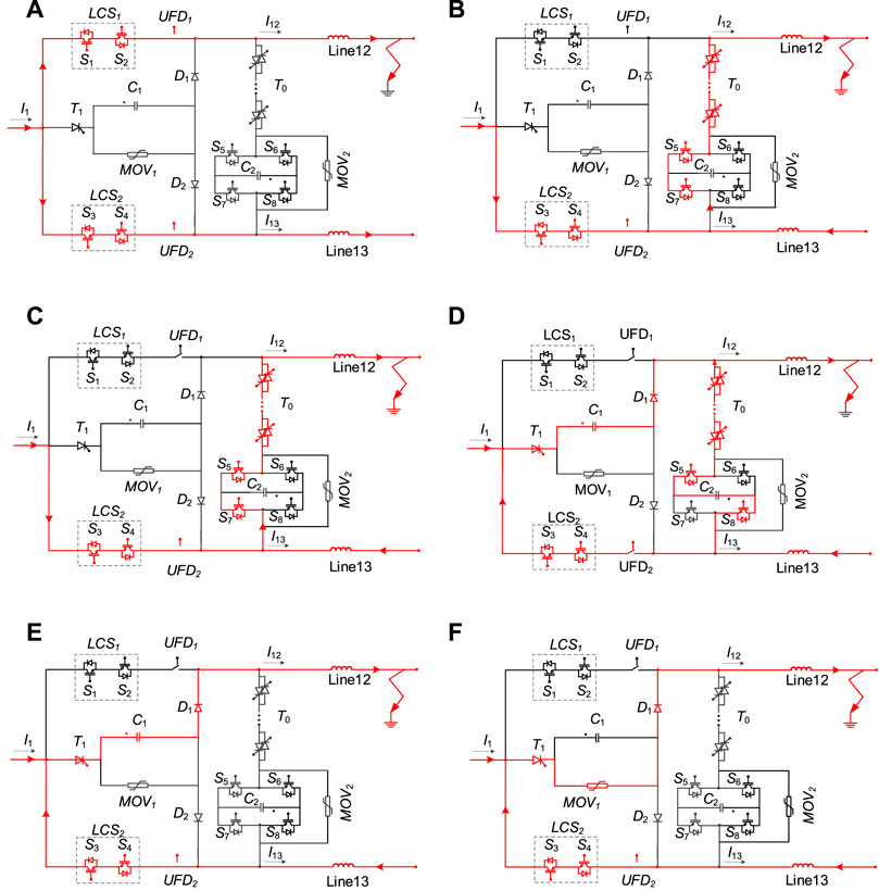
FIGURE 4. Operation of the SCR-IHCB for the transmission line fault. (A) Before t2. (B) t2-t3. (C) t3-t4 (D) t4-t5 (E) t5-t6 (F) t6-t7.
Stage 1(t1-t3): If a fault occurs on line12 at t1 and is detected at t2, S5, S7 and T0 will be switch on immediately, and then the IGBTs in LCS1 will all be switched off at t3, as shown in Figure 4B. The fault current is then commutated from transfer branch to the main breaker branches, and UFD1 will open within 2 m.
Stage 2(t3-t5): With UFD1 in open position at t4 as shown in Figure 4C. Then S7 switched off, and the S8 will be switched on, thyristor T1 will also be turned on immediately as shown in Figure 4D. Initially, T0 still is on-state, capacitor voltage Vc2 may suddenly increase in a short time, but its maximum value is strictly limited to the protection voltage VMOV2 by the parallel MOV2, that will protect the IGBT S5-S8 from exceeding its maximum withstand voltage. Fault current will keep charging C1 from zero-voltage state. The capacitor voltage Vc1 gradually increases from zero but it is smaller than the capacitor voltage of Vc2 which has been pre-charged in interline CFC mode, and a reverse voltage VT0 (VT0 = Vc1(t) −Vc2) will hereby be generated, the equivalent circuit is shown in Figure 5. The duration of reverse voltage should be larger than the requested recovery time, and the SCR string will be turn off reliably at t5 as shown in Figure 4E.
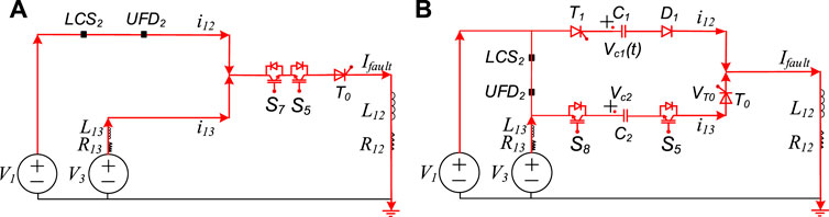
FIGURE 5. Implified equivalent circuit of current commutation process. (A) t3-t4 (B) t4-t5.
Stage 3(t5-t7): The fault current continuously charges C1. When Vc1 reaches the protection voltage of MOV1 at t6, the current flowing through C1 is transferred to MOV1 as shown in Figure 4F. Until fault current decreases to value that no longer maintain D1 conduction, the fault is cleared at t7.
3 Parameters design and analysis
3.1 Analysis of current commutation
Based on the fault blocking mode described in Section 2, the process of current commutation starts when the IGBTs in LCS1 are switched off at t3. Prior to the capacitor C1 is inserted at t4, the fault current is fed into the fault node through healthy nodes, it means the current of other stations will inject into line12, the equivalent circuit is given in Figure 5A. Ignoring the resistance of the IGBTs and thyristor which are much less than line resistance, the fault current ifault can be written as below:
Where V1 and V3 are the voltage of station 1 and station 3 that assumed to remain constant value throughout the process, R12 and L12 is the resistance and inductance value of line12 to fault point, R13 and L13 is the resistance and inductance value of line13.
From t4 to t5, the capacitor C1 and C2 are inserted into the system, the simplified equivalent circuit can be seen in Figure 5B. For capacitor C2, its voltage has a sudden increase in a short time and the maximum value is the clamping voltage of MOV2. The current i12 will charge the capacitor C1 from zero until trigger the clamping voltage of MOV1 at t6. According to Figure 5B, the differential equations from t4 to t5 can be expressed as:
where Vclamp2 is the clamping voltage of MOV2, the voltage of the capacitor C1 from t4 can be obtained:
Assuming Tscr is the minimum recovery time of SCR string, the SCR voltage VT0 can be expressed as:
The most important issue of parameter design of the proposed topology is to make sure that the duration of reverse voltage on the SCR string T0 must be larger than the minimum requested recovery time to make sure the current conducted thought the SCR reach a value below its threshold current and last long enough, thus the thyristor can be switched off reliably.
To meet the minimum recovery time of SCR under the worst situation, and the calculation process can be simplified:
The capacitor C1 and voltage of C2 can be chosen as:
Where Trv is the required reverse voltage time, Tscr is the minimum recovery time of T0. Imax is the maximum allowed breaking current of SCR-IHCB. α is a redundancy factor and must be larger than 1.
According to Eqs. 5, 6, a larger redundancy factor α increases the reliability of SCR-IHCB, but the capacitor value C1 and Vc2 becomes larger. A redundancy factor of 1.5∼2 is generally preferred. When the value of α is determined, the value of C1 and VC2 should be designed together, A smaller value of C1 means a faster blocking speed (tb in Figure 6) of the fault current because Vc1 can rise to VDC faster, but it also means that a higher VC2 value is required; a higher Vc2 value also means higher withstand voltage of S5-S7, IGBT-in-series or cascaded multi submodule topology can be used, but the cost and loss of the system will also increase. There exists a trade-off between system economy and fault current blocking speed, as shown in Figure 6.
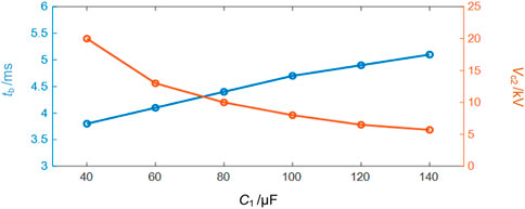
FIGURE 6. The relationship between C1, tb and Vc2.
3.2 Parameters calculation of MOV
The rated voltage for the MOVs of the typical HCB should be greater than 1.5 times the system voltage to quickly reduce the fault current to zero:
The total absorbing energy EMOV of MOV is associated with the energy storage components of system, which can be given by:
where LDC is the value of system equivalent inductance, Imax is the maximum value of fault current.
3.3 Device cost and loss analysis
In order to compare the improvements of the proposed SCR-IHCB, it is compared with the typical HCB+CFC solution which is not integrated (three ABB’s HCB solution (Häfner and Jacobson, 2011) in three lines with one CFC (Sau-Bassols and Gomis-Bellmunt, 2017)) in 10kV/1 kA three-port system, as shown in Figure 7. 4.5 kV IGBT(5SNA1200G452300) and 5.2 kV thyristor(T1451N) are selected in the comparison. The relative conduction loss and device cost of two solutions in the same voltage level are shown in Figure 8, where the ordinate is a relative value and “1” represents the maximum.
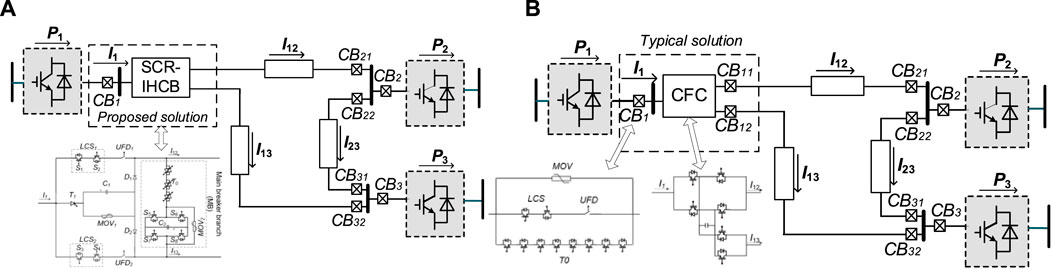
FIGURE 7. Detailed topologies of two solutions in 10kV/1 kA three-port system (A) Proposed SCR-IHCB; (B) Typical HCB+CFC solution.
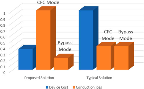
FIGURE 8. Economic comparison with two solutions in 10 kV three-port system.
As can be seen in Figure 8, the device cost of the proposed solution is much lower than that of typical HCB+CFC solution, because less HCBs are used and large number of fully-controlled semiconductor devices have been replaced by semi-controlled semiconductor devices.
The conduction loss in the proposed SCR-IHCB is much higher in CFC mode, but is lower in bypass mode compared with typical IGBT based HCB + CFC solution. Because in bypass mode, only the conduction loss of LCS is added with the proposed solution, but both conduction loss of IGBTs in LCS and CFC parts are added with the typical solution. Considering the investment and conduction loss in different mode together, the comprehensive cost during operation strongly depends on how often the SCR-IHCB need to operate in CFC mode to ensure stable grid conditions, therefore the comprehensive cost could be much lower than the typical solution in the application scenario where inter line power flow control is only needed occasionally.
4 Modeling and control methodology of CFC
In this section, the dynamic model of the proposed CFC is presented, using averaging technique where the terminals voltages are taken into consideration as setting values. Taking the first scenario for example, and the analysis can be extended to the rest of possible current configurations. We can see the current flow of the first scenario in the Figure 2.
The following set of equations describes the circuit of Figure 2A. This equivalent circuit was developed based on a reduction of the physical circuit layout, where: rxx and Lxx are the resistance and the inductance of the line xx originated from the CFC bus and carrying an instantaneous current ix, Vc1 is the capacitor voltage, V1 is the voltage at the bus where the CFC is connected to, V2 and V3 are the voltages at the end terminals of the lines, respectively.
Similarly, the state equations of Figure 2B, where the capacitor is discharging into line12, are as follows:
Assume the duty ratio of the charging mode1 is D. Multiplying Eqs. 8, 10 by D and (1−D), respectively, and adding the results to obtain the average model for the CFC for the scenario as follows:
At steady state, Eq. 11 can be written as Eq. 12:
Solving Eq. 12, the steady-state value of capacitor voltage is obtained as:
Eq. 13 gives an expression for the capacitor voltage as a function of the network parameters and the voltage drops across the cables connected to the CFC which represents the loading condition of the grid.
Given that the power taken from one line is equal to the power added to the other line, the power balancing between state 1 and state 2 as shown in Figure 2 is given by:
The relationship between I12 and I13 can be obtained from the above formula:
From the previous analysis the voltage ripple can be deduced and it is given by Eq. 16.
where ƒ is the switching frequency of the CFC.
A block diagram for the control scheme is shown in Figure 9. The control system has two nested PI controllers: an inner capacitor voltage controller and outer DC current controller. The outer controller regulates the DC line current by feeding a reference voltage to the inner voltage controller. The inner controller achieves the required capacitor voltage level by controlling the duty cycle.
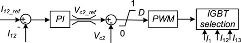
FIGURE 9. PI controller for CFC mode of SCR-IHCB.
5 MTDC network Simulation Studies
In this section, a simplified three-terminal HVDC system is simulated. As shown in Figure 1, the proposed SCR-IHCB topology is equipped at station 1 to adjust the power of line 12 and line 13. The practical parameter of the three-terminal HVDC system is shown in Table 2.

TABLE 2. Parameter of three-terminal HVDC system.
The currents flowing from the DC bus of station 1 and the transmission lines in presence of the SCR-IHCB are depicted in Figure 10. The SCR-IHCB operates in the bypass mode for 0 < t < 2s. Thereafter, the CFC changes its operation mode to CFC mode at 2s. Figures 10A, B implies that the SCR-IHCB can adjust the current bidirectionally in CFC mode. The short-circuit fault in line12 happens at time t = 4s. It can be seen in Figures 10A, B that the SCR-IHCB can quickly isolate the fault on line 12, and the transmission between station 1 and station 3 returned to normal (I1 = I13).
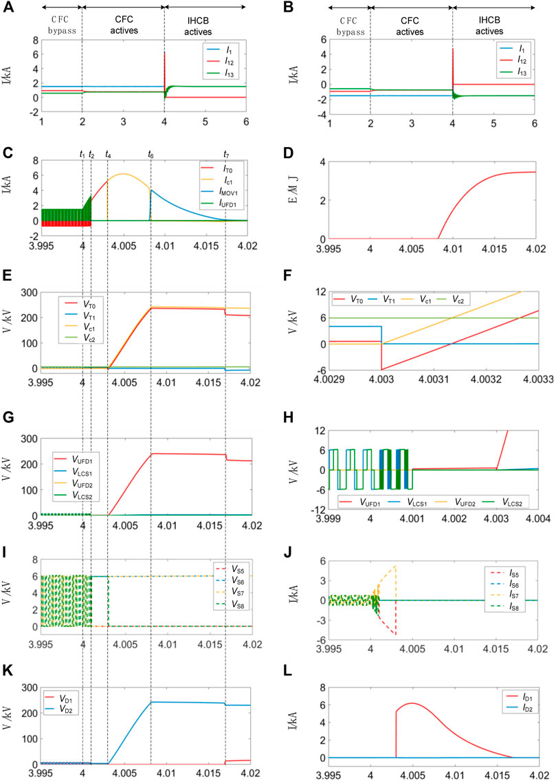
FIGURE 10. Performance of SCR-IHCB. (A) Current waveforms with forward power flow. (B) Reverse power flow. (C) Fault current transfer process. (D) Energy absorb by MOV1. (E) VT0, VT1, Vc1 and Vc2. (F) Details of VT0, VT1, Vc1 and Vc2. (G) Voltage of transfer branches. (H) Details of voltage of transfer branches. (I) VS5-VS8. (J) IS5-IS8. (K) VD1 and VD2. (L) ID1 and ID2.
As shown in Figure 10C, before the fault is detected in t = 4.001s, the SCR-IHCB is still working in CFC mode. when the system detects the fault, IHCB mode is activated, S5 and S7 conducts as mentioned above, the fault current goes through T0, and IT0 started to rise rapidly. After 2 m (waiting for the UFD1 completely open), the fault current was successfully transferred to charging path of the capacitor C1, Vc1 starts to rise (as shown in Figure 10E), in less than 5 m, the fault current (Ic1, ID1) reaches the peak value 6.1 kA. When Vc1 reaches the protection voltage of MOV1(250 kV as shown in Figure 10E), the fault current is transferred to MOV path (Imov1 in Figure 10C) and decreases to zero. The amount of absorbed energy of MOV1 reaches almost 3.6 MJ as shown in Figure 10D. When the fault current drops to zero, the value of VT0 return to VDC-Vc2, and the thyristor T1 needs to withstand a reverse voltage of Vc1-VDC, about 50 kV as shown in Figure 10E.
Figure 10F shows that the reverse voltage VT0 (VT0 = Vc1 −Vc2) is generated at 4.003s, and the duration time is about 140us, much larger than the minimum requested recovery time of SCR string in (Jamshidi Far and Jovcic, 2018).
Figures 10G, H show the voltage waveform of two transfer branch, LCS1 and LCS2 works in CFC mode before fault is detected. UFD2 and LCS2 remain on-state to keep transmission of station1 and station 3 after fault blocking, LCS1 switch off at 4.001s, and the UFD1 takes 2 m to completely open, then the voltage on UFD1 increases with Vc1.
Figures 10I, J show the voltage and current of the S5-S7. Obviously, the operation sequence of S5-S8 is consistent with the theoretical analysis, and the maximum withstand voltage of S5-S8 is limited to the given voltage of Vc2, the maximum current is equal to the value when the fault current transferred from T0 branch to C1 branch.
Figures 10K, L show that the maximum withstand voltage and current of diode strings (D1 and D2) are consistent with the maximum voltage of Vc1 and maximum fault current.
6 Experimental Studies
Considering that the proposed SCR-IHCB topology is a symmetrical structure for fault blocking of two adjacent lines; therefore, the verification for the current opening process of one line is enough. A scale-down prototype is built for verifying the concept of the feasibility of the SCR-IHCB, as shown in Figure 11A, the component marks in Figure 11A are consistent with those in Figure 1A. The diagram of the experimental system is depicted in Figure 11B and the system parameters are listed in Table 3.
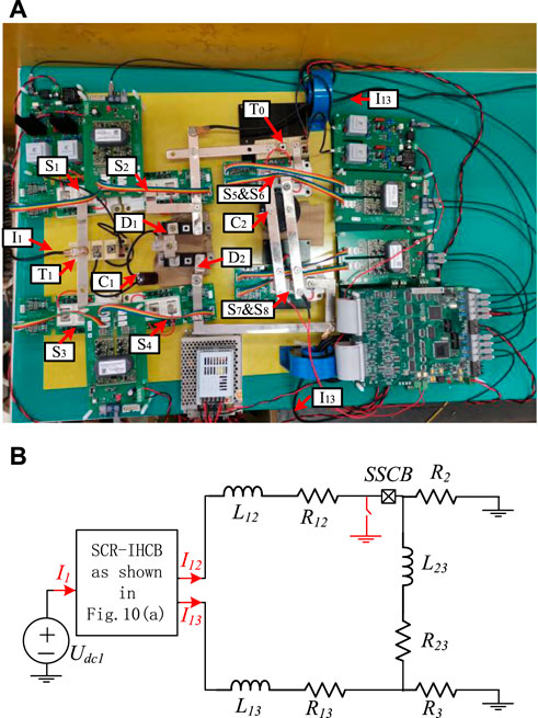
FIGURE 11. Experimental system. (A) Photograph of the scale down SCR-IHCB prototype. (B) Circuit diagram of three-terminal test platform.
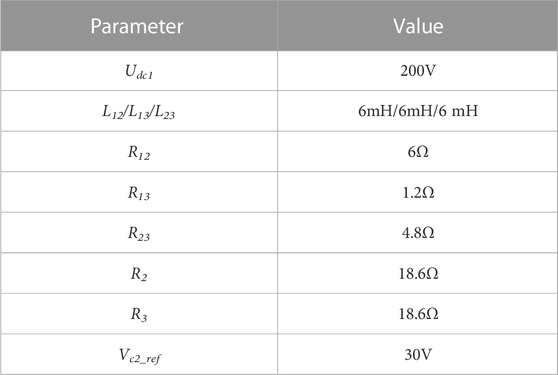
TABLE 3. Parameters of the experimental system.
6.1 Fault current blocking
The fault blocking waveforms of the SCR-IHCB are shown in Figure 12. It can be seen that after the fault occurs at t0, after a detection time of 1 m, the IGBT in LCS is turned OFF, fault current is transferred to main breaker branch at t1. A 2 m delay is set between t1 and t2 to simulate the opening time of mechanical switch. The IGBTs in main breaker branch is turned off at t2, while C1 is charged and the fault current is successfully interrupted eventually at t3.
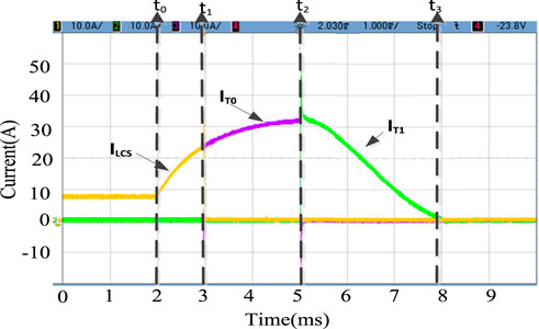
FIGURE 12. Measured fault-interrupting waveforms of the DC Fault Mode.
The detailed waveforms of the thyristor T0 recovery stage is shown in Figure 13. When the value of 220 μF is chosen for C2, the SCR-IHCB has Δt > 100us as shown in Figure 13A, and the thyristor is turned off successfully, the fault current of the system (Isys) is quickly transferred from T0 to T1 (IT0 and IT1 in Figure 13A), the voltage of T0 (VT0) rises as C1 is charged by the system fault current.
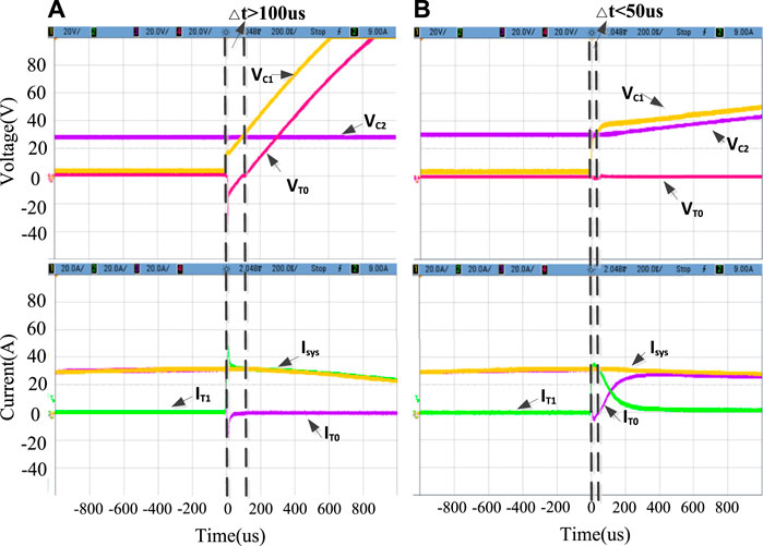
FIGURE 13. Measured waveforms during the thyristor recovery stage at (A) C2 = 220μF; (B) C2 = 100 μF.
When the value of C2 is reduced to 100 μF, the SCR-IHCB has Δt < 50us, smaller than tq in datasheet of thyristor SKKT62 which is used in our experiment. It is obvious that the thyristor has failed to turn off, the fault current of the system (Isys) continues to flow through T0, Capacitor C1 and capacitor C2 are connected in parallel, and the voltage rises synchronously.
6.2 Current control
The CFC function is also verified by experiments, as shown in Figure 14. At the beginning, the current at line 12 (I12) is 12A and at line 13 (I13) is 6A at first. At t = 10 m, the CFC begins to work and the current at line 13 (I13) begins to increase and the current at line 12 (I12) decreases meanwhile. After 5 m, the line current forms a new steady state. It can be found that the controller can keep capacitor voltage constant at 30V (Vc2) during current regulation.
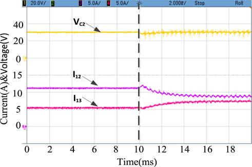
FIGURE 14. Measured fault-interrupting waveforms of the current control mode.
7 Conclusion
In this paper, a SCR string and H-bridge module based interline hybrid circuit breaker topology with current flow control function is proposed. The operation principles in normal operation mode and DC fault mode are analyzed, the parameters design principle is also presented in detail. The simulation and experiment results from a meshed HVDC grid model confirm the operational performance of the proposed topology. Compared with other solutions, the topology design is more economical and simpler because only one bidirectional SCR string and only one H-bridge module is needed for two adjacent lines, no additional capacitor pre-charge circuits and inductors are required, the current flow control function is also integrated without additional components.
Data availability statement
The original contributions presented in the study are included in the article/Supplementary Material; further inquiries can be directed to the corresponding author.
Author contributions
QZ: Writing—Original Draft, Experimental Studies and Visualization. JZ: Conceptualization, Methodology and Supervision. XG: Writing—Original Draft and Simulation Studies. QH: Editing, Parameters Design. JY: Process Analysis, Supervision. TW: Supervision.
Funding
This work was supported in part by the National Natural Science Foundation of China under Grant 51607171, in part by The Institute of Electrical Engineering, CAS under Grant E155610301 and E155610201.
Acknowledgments
This is a brief acknowledgement of the contributions of individual colleagues, institutions, or agencies that assisted the writers’ efforts in the writing of this article.
Conflict of interest
The authors declare that the research was conducted in the absence of any commercial or financial relationships that could be construed as a potential conflict of interest.
Publisher’s note
All claims expressed in this article are solely those of the authors and do not necessarily represent those of their affiliated organizations, or those of the publisher, the editors and the reviewers. Any product that may be evaluated in this article, or claim that may be made by its manufacturer, is not guaranteed or endorsed by the publisher.
References
Akhmatov, V., Callavik, M., Franck, C. M., Rye, S. E., Ahndorf, T., Bucher, M. K., et al. (2014). Technical guidelines and prestandardization work for first HVDC grids. IEEE Trans. Power Deliv. 29 (1), 327–335. doi:10.1109/TPWRD.2013.2273978
Balasubramaniam, S., Liang, J., and Ugalde-Loo, C. E. (2015). “Control, dynamics and operation of a dual H-bridge current flow controller,” in IEEE Energy Conversion Congress and Exposition (Montreal, Canada: ECCE). doi:10.1109/ecce.2015.7309996
Chang, A. H., Sennett, B. R., Avestruz, A.-T., Leeb, S. B., and Kirtley, J. L. (2016). Analysis and design of DC system protection using Z-source circuit breaker. IEEE Trans. Power Electron. 31 (2), 1036–1049. doi:10.1109/TPEL.2015.2415775
Chen, Z., Yu, Z., Zhang, X., Wei, T., Lyu, G., Qu, L., et al. (2018). Analysis and experiments for IGBT, IEGT, and IGCT in hybrid DC circuit breaker. IEEE Trans. Ind. Electron. 65 (4), 2883–2892. doi:10.1109/TIE.2017.2764863
Corzine, K. A., and Ashton, R. W. (2012). A new Z-source DC circuit breaker. IEEE Trans. Power Electron. 27 (6), 2796–2804. doi:10.1109/tpel.2011.2178125
Cwikowski, O., Sau-Bassols, J., Chang, B., Prieto-Araujo, E., Barnes, M., Gomis-Bellmunt, O., et al. (2018). Integrated HVDC circuit breakers with current flow control capability. IEEE Trans. Power Deliv. 33 (1), 371–380. doi:10.1109/TPWRD.2017.2711963
Dong, Z., Ren, R., Zhang, W., Wang, F. F., and Tolbert, L. M. (2021). Instability issue of paralleled dies in an SiC power module in solid-state circuit breaker applications. IEEE Trans. Power Electron. 36 (10), 11763–11773. doi:10.1109/TPEL.2021.3068608
Flourentzou, N., Agelidis, V. G., and Demetriades, G. D. (2009). VSC-based HVDC power transmission systems: An overview. IEEE Trans. Power Electron. 24 (3), 592–602. doi:10.1109/TPEL.2008.2008441
Grieshaber, W., Davidson, C. C., Whitehouse, R. S., Dupraz, J.-P., and Barker, C. D. (2015). “A new ultra-fast HVDC Circuit breaker for meshed DC networks,” in 11th IET International Conference on AC and DC Power Transmission (Birmingham, UK): Institution of Engineering and Technology), 047. doi:10.1049/cp.2015.0021
Guo, Y., Li, H., Gu, G., Zeng, D., and Wang, G. (2021). A multiport DC circuit breaker for high-voltage DC grids. IEEE J. Emerg. Sel. Top. Power Electron. 9 (3), 3216–3228. doi:10.1109/JESTPE.2020.3018646
Guo, Y., Wang, G., Zeng, D., Li, H., and Chao, H. (2020). A thyristor full-bridge-based DC circuit breaker. IEEE Trans. Power Electron. 35 (1), 1111–1123. doi:10.1109/TPEL.2019.2915808
Häfner, J., and Jacobson, B. (2011). “Proactive hybrid HVDC breakers-A key innovation for reliable HVDC grids,” in Integrating Supergrids and Microgrids International Symposium (Bologna, Italy), 1–8.
Häfner, J., and Jacobson, B. (2011). “Proactive hybrid HVDC breakers-a key innovation for reliable HVDC grids,” in Proceedings of the international symposium on integrating supergrids and microgrids (Bologna, Italy), 1–8.
Jamshidi Far, A., and Jovcic, D. (2018). Design, modeling and control of hybrid DC circuit breaker based on fast thyristors. IEEE Trans. Power Deliv. 33 (2), 919–927. doi:10.1109/TPWRD.2017.2761022
Keshavarzi, D., Ghanbari, T., and Farjah, E. (2017). A Z-source-based bidirectional DC circuit breaker with Fault Current limitation and interruption capabilities. IEEE Trans. Power Electron. 32 (9), 6813–6822. doi:10.1109/TPEL.2016.2624147
Kontos, E., Ramirez-Elizondo, L. M., Franck, C. M., Bauer, P., and Bauer, P. (2018). Multiline breaker for HVDC applications. IEEE Trans. Power Deliv. 33 (3), 1469–1478. doi:10.1109/TPWRD.2017.2754649
Li, C., and Wang, S. (2018). Interlink hybrid DC circuit breaker. IEEE Trans. Ind. Electron. 65 (11), 8677–8686. doi:10.1109/TIE.2018.2803778
Li, W., Wang, Y., Wu, X., and Zhang, X. (2019). A novel solid-state circuit breaker for on-board DC microgrid system. IEEE Trans. Ind. Electron. 66 (7), 5715–5723. doi:10.1109/TIE.2018.2854559
Lin, W., Jovcic, D., Nguefeu, S., and Saad, H. (2016). “Modelling of high power mechanical DC circuit breaker,” in IEEE PES Asia-Pacific Power and Energy Engineering Conference (Brisbane, Australia: APPEEC), 1–5. doi:10.1109/APPEEC.2015.7381002
Liu, G., Xu, F., Xu, Z., Zhang, Z., and Tang, G. (2017). Assembly HVDC breaker for HVDC grids with modular multilevel converters. IEEE Trans. Power Electron. 32 (2), 931–941. doi:10.1109/TPEL.2016.2540808
Majumder, R., Barupati, P., Jonsson, T. U., and Velotto, G. (2017). An alternative method to build DC switchyard with hybrid DC breaker for DC grid. IEEE Trans. Power Deliv. 32 (2), 713–722. doi:10.1109/TPWRD.2016.2582923
Mokhberdoran, A., Gomis-Bellmunt, O., Silva, N., and Carvalho, A. (2018a). Current flow controlling hybrid DC circuit breaker. IEEE Trans. Power Electron. 33 (2), 1323–1334. doi:10.1109/TPEL.2017.2688412
Mokhberdoran, A., Van Hertem, D., Silva, N., Leite, H., and Carvalho, A. (2018b). Multiport hybrid HVDC circuit breaker. IEEE Trans. Ind. Electron. 65 (1), 309–320. doi:10.1109/TIE.2017.2719608
Ray, A., Rajashekara, K., Banavath, S. N., and Pramanick, S. K. (2019). Coupled inductor-based zero current switching hybrid DC circuit breaker topologies. IEEE Trans. Ind. Appl. 55 (5), 5360–5370. doi:10.1109/TIA.2019.2926467
Sander, R., Suriyah, M., and Leibfried, T. (2018). Characterization of a countercurrent injection-based HVDC circuit breaker. IEEE Trans. Power Electron. 33 (4), 2948–2956. doi:10.1109/TPEL.2017.2709785
Sano, K., and Takasaki, M. (2014). A surgeless solid-state DC circuit breaker for voltage-source-converter-based HVDC systems. IEEE Trans. Ind. Appl. 50 (4), 2690–2699. doi:10.1109/TIA.2013.2293819
Sau-Bassols, J., and Gomis-Bellmunt, O. (2017). Modelling and control of an interline current flow controller for meshed HVDC grids. IEEE Trans. Power Deliv. 32 (1), 11–22. doi:10.1109/TPWRD.2015.2513160
Shi, Z. Q., Zhang, Y. K., Jia, S. L., Song, X. C., Wang, L. J., and Chen, M. (2015). Design and numerical investigation of A HVDC vacuum switch based on artificial current zero. IEEE Trans. Dielectr. Electr. Insul. 22 (1), 135–141. doi:10.1109/TDEI.2014.004533
Shu, J., Wang, S., Ma, J., Liu, T., and He, Z. (2020). An active Z-source DC circuit breaker combined with SCR and IGBT. IEEE Trans. Power Electron. 35 (10), 10003–10007. doi:10.1109/TPEL.2020.2980543
Wang, S., Ming, W., Ugalde Loo, C. E., and Liang, J. (2022). A low-loss integrated circuit breaker for HVDC applications. IEEE Trans. Power Deliv. 37 (1), 472–485. doi:10.1109/TPWRD.2021.3063515
Wang, Y., Li, W., Wu, Xuanyu., and Wu, Xiaohua. (2019). A novel bidirectional solid-state circuit breaker for DC microgrid. IEEE Trans. Ind. Electron. 66 (7), 5707–5714. doi:10.1109/TIE.2018.2878191
Xiao, H., Xu, Z., Xiao, L., Gan, C., Xu, F., and Dai, L. (2020). Components sharing based integrated HVDC circuit breaker for meshed HVDC grids. IEEE Trans. Power Deliv. 35 (4), 1856–1866. doi:10.1109/TPWRD.2019.2955726
Xu, X., Chen, W., Liu, C., Sun, R., Li, Z., and Zhang, B. (2021). An efficient and reliable solid-state circuit breaker based on mixture device. IEEE Trans. Power Electron. 36 (9), 9767–9771. doi:10.1109/TPEL.2021.3067316
Zhang, X., Yu, Z., Chen, Z., Zhao, B., and Zeng, R. (2020). Optimal design of diode-bridge bidirectional solid-state switch using standard recovery diodes for 500-kV high-voltage DC breaker. IEEE Trans. Power Electron. 35 (2), 1165–1170. doi:10.1109/TPEL.2019.2930739
Keywords: hybrid circuit breaker, interline, SCR string, current flow control, H-bridge submodule
Citation: Zeng Q, Zhu J, Guo X, Huo Q, Yin J and Wei T (2023) A low-cost current flow controlling interline hybrid circuit breaker combined with SCR and H-bridge sub-module. Front. Energy Res. 10:1081826. doi: 10.3389/fenrg.2022.1081826
Received: 27 October 2022; Accepted: 28 November 2022;
Published: 23 January 2023.
Edited by:
Tahir Khurshaid, Yeungnam University, South KoreaReviewed by:
Liansheng Huang, Hefei Institutes of Physical Science (CAS), ChinaTohid Rahimi, Carleton University, Canada
Copyright © 2023 Zeng, Zhu, Guo, Huo, Yin and Wei. This is an open-access article distributed under the terms of the Creative Commons Attribution License (CC BY). The use, distribution or reproduction in other forums is permitted, provided the original author(s) and the copyright owner(s) are credited and that the original publication in this journal is cited, in accordance with accepted academic practice. No use, distribution or reproduction is permitted which does not comply with these terms.
*Correspondence: Jin Zhu, emh1amluQG1haWwuaWVlLmFjLmNu