 Hongxin Yang
 Zishun Peng1,2*†
- 1College of Electrical and Electronic Engineering, Wenzhou University, Wenzhou, China
- 2National-local Joint Engineering Research Center for Digitalized Electrical Design Technology, Wenzhou university, Wenzhou, China
- 3Zhejiang Quality Inspection Center of High and Low Voltage Electrical Product, Wenzhou, China
The fault diagnosis of the inverter is fundamental to energy intelligence. Due to the complex characteristics of the inverter (e.g., high-dimensional decision and poor stability), it is challenging to solve the problem using traditional fault diagnosis methods. Recently, artificial intelligence (AI)-based approaches have emerged as the most promising methods. However, they often require to set hyperparameters manually, which hinders further AI-based applications in fault diagnosis of inverters. To fill the gap, we propose an inverter fault diagnosis method using fast Fourier Transform (FFT) and evolutionary neural network. This method combines the amplitude of low-frequency harmonic component of the three-phase inverter output current which is obtained by FFT and the average value in a period of three-phase inverter output current into the fault eigenvector. This method uses an evolutionary neural network trained by combining genetic algorithm (GA), ant colony optimization (ACO) algorithm and Back-propagation (BP) algorithm to realize fault diagnosis. This method can effectively resist noise interference and reduce the number of independent variables in the part of feature extraction, so that it can simplify the network model. In addition, this method can avoid the network training from trapping in local optima in the part of fault classification, with high accuracy and fast response speed. The experimental results show that the proposed algorithm and method of fault feature extraction can effectively detect and locate the insulated-gate bipolar transistor (IGBT) with open circuit (OC) fault in three-phase inverter, and can be applied to online monitoring.
1 Introduction
With the development of industrial automation and intelligent manufacturing, industrial robots are gradually replacing manual work. In order to prevent the problem of robot operation accuracy caused by data loss in case of abnormal voltage or mains power interruption, the control system of industrial robots is usually equipped with uninterruptible power supply. As the core component of uninterruptible power supply, the reliability of inverter has been widely concerned. Industrial demands put forward strict requirements for inverter (Ahmad et al., 2021; Yan et al., 2021) (High-voltage and high-power output, small system electromagnetic interference, low total harmonic distortion rate of output voltage, and small switch loss, etc.). Due to the wide application of wide band gap semiconductor devices, IGBT of converter is easily damaged, because it needs to withstand high-frequency interruption, high-voltage and high-current impact and temperature impact (Li et al., 2021). When the IGBT fails, the output current of the inverter will be seriously distorted that will result in irreversible damage to the subsequent equipment. Therefore, the fault diagnosis of the inverters has research significance for the industrial robot control system, and provides a basis for the research of the fault tolerance of inverter control strategy.
Fault diagnosis methods are mainly divided into model-based methods, signal-based methods, and knowledge-based methods. Model-based methods use the output state of the circuit that is evaluated by establishing an accurate mathematical model of the inverter to carry out fault diagnosis. The accuracy is high, but the modeling process is complex. For example, Wang et al. proposed a node path modeling method for fault detection Wang et al. (2021), this method used current path state and node potential to represent the circuit’s working mode, and located transistor faults according to the deviation of output current. Knowledge-based methods depend on the given knowledge in the relevant fields. They need to have a certain understanding of the system structure and summarize the relationship between the normal state of the system and different fault states. These methods have some limitations, such as slow derivation process, difficulty in establishing knowledge base and poor timeliness. For example, Kou et al. proposed a method based on knowledge driven and data driven Kou et al. (2020), which used the Concordia transform (knowledge driven) for feature conversion, and used the random forests technique (data driven) to train the fault diagnosis classifier for inverter fault diagnosis. Signal-based methods can directly analyze the measured signal to obtain fault characteristics. Artificial intelligence methods can be used for fault diagnosis. The fault feature extraction methods include Fourier Transform and wavelet transform, etc. Fault classification adopts machine learning methods, such as BP neural networks, support vector machines, Multi-layer Perceptron, etc. These methods have a high accuracy, but need to collect a large number of sample data to train the network. For example, Khomfoi et al. took the output voltage of the inverter bridge arm as the measured signal, used FFT to obtain the 40 high-order harmonic amplitudes as the fault diagnosis data. This method designed five multilayer feed forward networks, where the number of input nodes, hidden nodes, and output nodes were 40, 2, and 1, to operate in parallel for fault location. The classification performance could reach 98% (Khomfoi and Tolbert, 2007), but the data dimension was large and the network structure was complex. And Phaneendra Babu et al. built a Multilayer Perceptron neural network, where the number of input nodes, hidden nodes, and output nodes were 40, 12, and 1, to run for fault location, with 99% classification performance Phaneendra Babu et al. (2008).
In recent years, the signal-based methods are improving, but there are still shortcomings. In the traditional fault diagnosis methods based on FFT, the problems of high eigenvector dimension and too many independent variables lead to the complex structure of the neural network, slow response in engineering applications, and poor anti-interference. Cai et al. used FFT to extract the signal characteristics of line voltage, and used principal component analysis to reduce the dimension of eigenvector. They used Bayesian networks for fault diagnosis (Cai et al., 2017). This method made full use of fault information in samples, but it was difficult to resist high-frequency noise interference, and the original data dimension was huge. To reduce the dimension of eigenvector, it required 10 PCs to run simultaneously for data processing, which was very complex. Ji et al. used Park transform to obtain the fundamental amplitude of three-phase current as the characteristic variable of fault detection and divided the fault types in detail, and used BP neural network and logic judgment to achieve fault location (Ji and Liu, 2018). Although this method reduced the dimension of eigenvector, but it made the fault classification complex. What’s more, the algorithm used in it is easy to trap in local optima, resulting in low network accuracy.
To solve the above problems, this paper presents a diagnostic method for inverters based on FFT and evolutionary neural network. This method collects the output current of the three-phase inverters as measured signal. Firstly, the amplitudes of the DC component, fundamental wave and second harmonic of the output current under fault state are extracted through FFT, and the average value in a period is calculated and marked, then the above components are combined to obtain the eigenvector. This process can effectively reduce the number of variables, so that it can simplify the network model. Secondly, a neural network model is established, GA, ACO, and BP algorithm are combined to train the network. This method discretizes the solution interval of weight, uses GA and ACO to locate the optimal weight to a certain subinterval, and then uses BP algorithm to obtain the optimal weight. This process combines the advantages of the three algorithms, reduces the search time, accelerates convergence speed, avoids trap in local optima, and improves the solution efficiency. Finally, the trained network is applied to fault diagnosis of three-phase inverter. This method can realize different fault classification, accurately locate the fault point, and has high diagnostic accuracy. In addition, this is a software-based method, which reduces the hardware cost, and has filtering effect in the phase from signal acquisition to fault feature extraction, so that the influence of noise can be eliminated, and the response is fast, so it can be used for online monitoring.
This paper consists of the following parts: First, the fault of three-phase inverter is analyzed. Secondly, according to the characteristics of three-phase inverter output current under fault conditions, a fault feature extraction method based on FFT is proposed. Then an evolutionary network is proposed and the algorithm flow is analyzed in detail. Finally, MATLAB/Simulink is used to build a simulation model of three-phase inverter, and LabVIEW is used to build a virtual instrument for data acquisition. Through the joint simulation between the two, eigenvectors under fault state are extracted for network training. At the same time, the training results of the algorithm proposed in this paper, hybrid GA-BP algorithm, hybrid ACO-BP algorithm and traditional BP algorithm under the same training samples and network architecture are compared and analyzed.
2 Fault analysis
Inverters are widely used in power systems, and their reliability directly affects the security and stability of power supply systems. Affected by uncertain factors such as working environment, aging, electromagnetic interference, etc., power devices become the most vulnerable components of the inverter (Cao et al., 2021). The common fault types are OC faults and short circuit (SC) faults of power devices.
2.1 Topology of three-phase inverter
This paper takes three-phase inverter as the research object and the topology of three-phase inverter is shown in Figure 1 (Hu et al., 2011). As can be seen from Figure 1, Udc, Cdc, Sn (n = 1,2,3,4,5,6), Dn (n = 1,2,3,4,5,6), Ln (n = 1,2,3), Cn (n = 1,2,3), and Rn (n = 1,2,3) represent the DC voltage, DC link capacitor, IGBTs, antiparallel connected diodes, filter inductance, filter capacitor, and load, respectively.
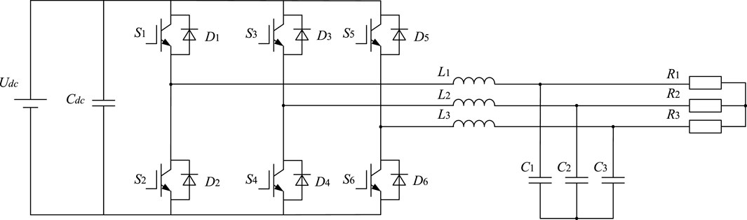
FIGURE 1. Topology of three-phase inverter.
The controller controls the switching on and off of the IGBTs by generating pulse width modulation wave, inverter filters the harmonics through the filter circuit so as to leave the fundamental wave, then it can convert DC power into three-phase alternating current power.
2.2 Short circuit fault analysis of three-phase inverter
When the IGBT in the inverter has an SC fault, for example, when the IGBT S2 occurs SC fault, as shown in Figure 2, S1 is turned on under the control signal, which will cause a short circuit to the DC source. In this case, the current in the circuit will increase sharply, which will cause the DC source, other IGBTs and even the whole circuit to burn out. In engineering application, the IGBT in the inverter is usually equipped with short circuiting protective circuit. When the IGBT is short circuited, the short circuiting protective circuit will react immediately, and then turn the SC fault into the OC fault (Li, 2020).
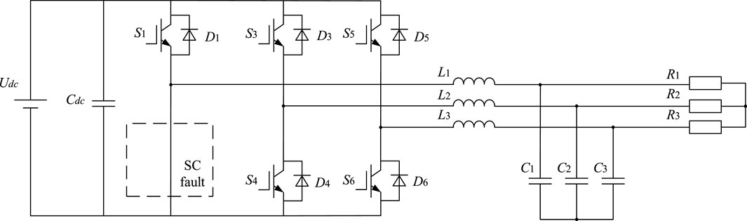
FIGURE 2. Topology of three-phase inverter with SC fault of S2.
2.3 Open circuit fault analysis of three-phase inverter
When the IGBT has an OC fault, it cannot flow current, and the corresponding part of the inverter output current is missing. For example, when the IGBT S2 of the lower bridge arm has an OC fault, its topology is shown in Figure 3, and its three-phase output current and its amplitude spectrum are shown in Table 1. It can be found that the negative half wave of phase A current disappears, the current waveform of phase B and C is severely distorted, and the harmonic content increases significantly. Similarly, it can be seen that when the IGBT S1 of the upper bridge arm fails, the positive half wave of the corresponding output current will disappear, and the output current waveform of the other two phases will be severely distorted. This situation makes normal power supply impossible. This paper will mainly diagnose the OC fault of the inverter. In practical application, the fault of the inverter is usually the OC fault of one or two IGBTs, and the simultaneous OC fault of three IGBTs is rare. This paper focuses on the OC fault of one or two IGBTs.

FIGURE 3. Topology of three-phase inverter with OC fault of S2.
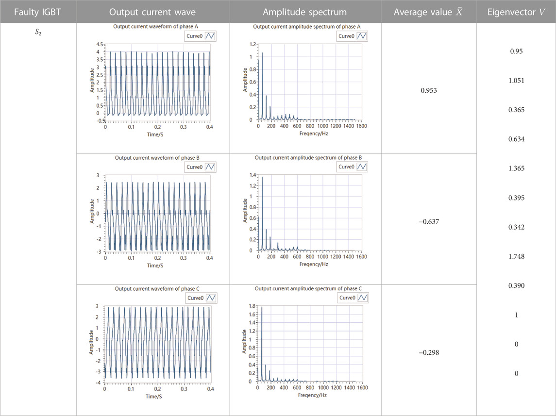
TABLE 1. Fault eigenvector and amplitude spectra of phase A, B, and C with S2 failure.
There are six cases when the OC fault happens on single IGBT. There are 15 cases when the OC fault happens on two IGBTs at the same time.
3 Fault feature extraction
The traditional fault, extraction method has high feature dimension and is difficult to resist noise interference. This paper proposes a fault feature extraction method. First, the output current of three-phase inverter is collected and the amplitude spectrum is obtained through FFT. According to the amplitude spectrum, the amplitudes of DC component, fundamental wave, and second harmonic of the output current of phase A, B, and C are obtained. Secondly, the average values in a period of the output current of phase A, B, and C are calculated and marked. The 12-dimension fault eigenvector under fault condition is obtained. This method collects the amplitudes of specific low-frequency components as the diagnosis data, which can effectively avoid high-frequency interference caused by noise. The block diagram is shown in Figure 4.
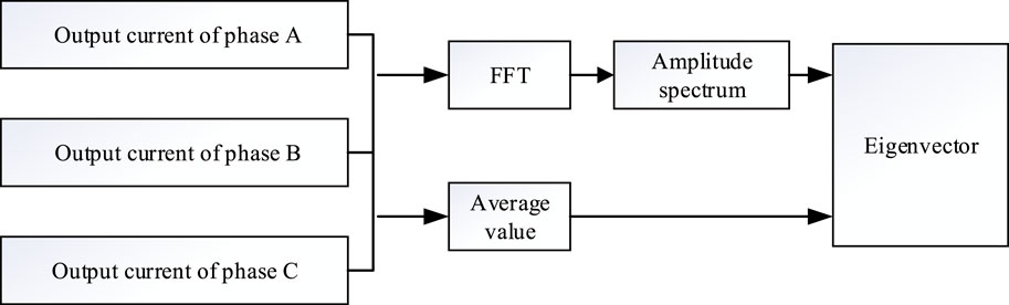
FIGURE 4. Block diagram of fault feature extraction.
3.1 Fast Fourier transform
Fourier Transform can convert time domain signal into a series of sinusoidal signals of different frequencies and amplitudes (Bi et al., 2021), and then it can get the amplitude spectrum of the time domain signal.
The Fourier Transform of the analog signal
where
FFT is a fast algorithm of DFT (Guo et al., 1998). In the FFT formula, the DFT equitation
3.2 Average value
The average value in a period of a periodic signal is:
where
3.3 Feature extraction
When the IGBT of the inverter has an OC fault, its topology changes, resulting in distortion of the output current. When the IGBTs on different bridge arms fail, the amplitude spectra of their output current waveform are different, but when the IGBTs with OC faults are at different positions of the same bridge arm, the amplitude spectra of their output current waveform are the same. It can be seen from Section 2.3, that if the IGBT on the same bridge arm fails, according to its location, its output current will have the loss of positive half wave or negative half wave. Therefore, according to the characteristics of the disappearance of positive half wave or negative half wave and the increase of harmonic content under the fault state, the method proposed in this paper extracts features from the amplitude spectrum and average value on one cycle of inverter output current for fault diagnosis. First, the output current of three-phase inverter is collected, and the amplitude spectrum is obtained through FFT. According to the amplitude spectra, the amplitudes of DC component, fundamental wave, and second harmonic of the output current of phase A, B, and C are obtained, and recorded as
The S2 failure, S4, and S6 failure simultaneously, S3 and S5 failure simultaneously are taken as examples to verify the effectiveness of the proposed fault exaction method, fault eigenvectors and amplitude spectra of phase A, B, and C are shown in Tables 1–3.
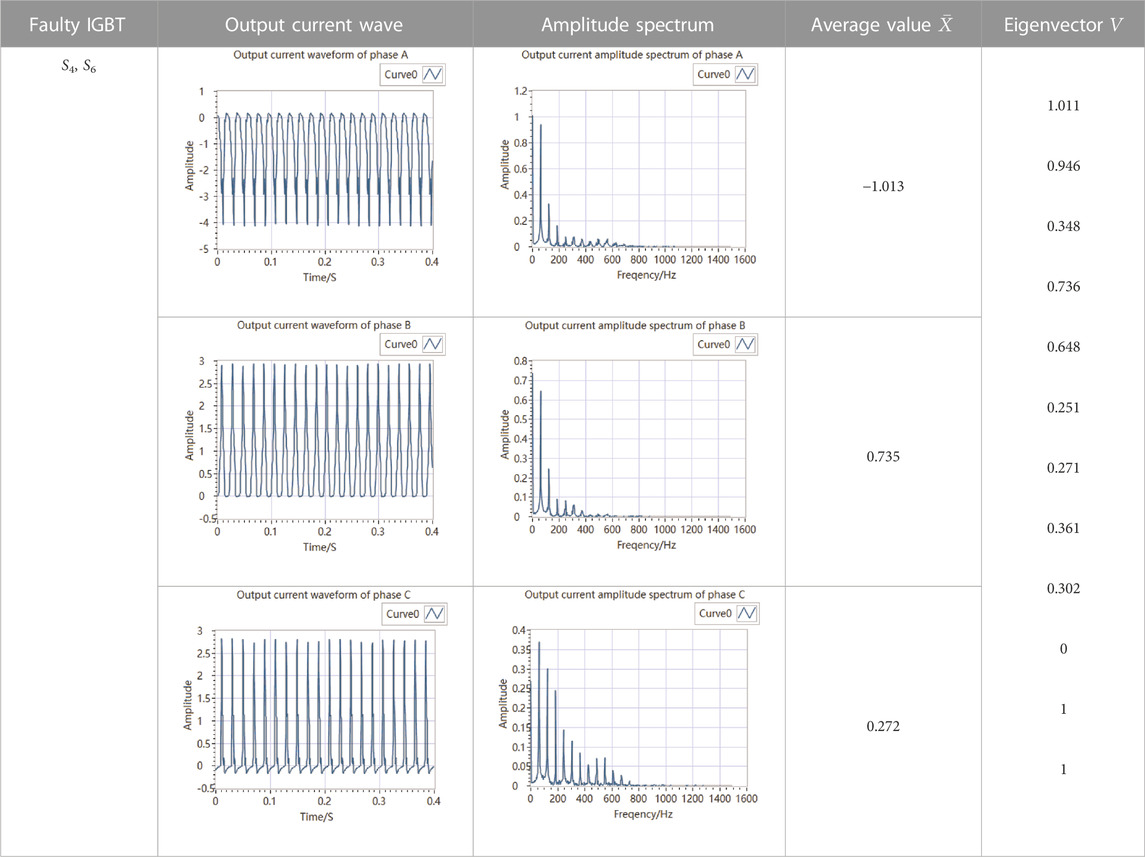
TABLE 2. Fault eigenvector and amplitude spectra of phase A, B, and C with S4 and S6 failure simultaneously.
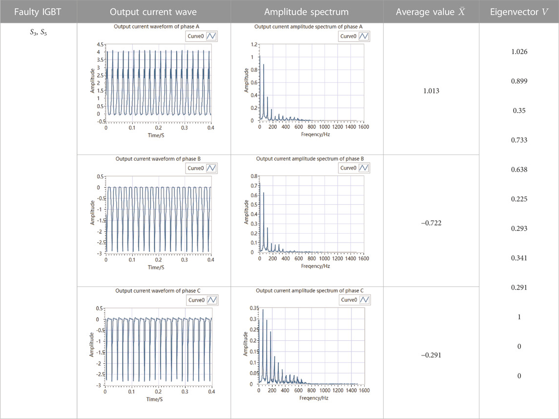
TABLE 3. Fault eigenvector and amplitude spectra of phase A, B, and C with S3 and S5 failure simultaneously.
Based on the above tables, for each fault, the eigenvectors obtained by the fault exaction method proposed in this paper are different, which can be used for fault diagnosis of three-phase inverter.
4 Evolutionary neural network
BP algorithm is the most widely used in neural network training method, and its essence is a learning algorithm based on stochastic gradient descent. BP neural network is highly dependent on the initial connection weight values, which makes the neural network training easy to trap in local optima. In the late training period, the output neurons are prone to premature saturation. This will affect the convergence speed and learning accuracy of the neural network (Hongjiao, 2019; Lei et al., 2020). Although the appeal problems can be solved by appropriately increasing the number of hidden layers and hidden nodes, it will increase the complexity of the network structure, training time, and computation. This paper proposes an evolutionary neural network, which combines the global search of GA and ACO with the local search of BP algorithm to train the network weight to the optimal value, and is applied to inverter fault detection.
4.1 Genetic algorithm
GA is a simulation study of the evolution of biosystem (Yu et al., 2018; Lambora et al., 2019; Tao et al., 2021). It is a random global optimization algorithm. It simulates the functions of selection, crossover, mutation and other functions in genetics. Selection and crossover maintain the most suitable genetic information for the current iteration, but these two operations easily make network training trap in local optima, and mutation operations can maintain the diversity of the population. In each operation, the selection of genes is random to expand the search space and avoid trapping in local optima. Through inheritance and evolution of generations in a population, more excellent individuals are generated, and the optimal solution of the problem is finally obtained (Ma et al., 2021b; Ma et al., 2021c).
4.2 Ant colony optimization algorithm
ACO is a bionic algorithm that imitates the behavior of ants in nature (Yu et al., 2018; Yang and Shi, 2019; Mohamed et al., 2021). In the process of optimization, the path is selected according to the pheromone on the path, and roulette is used to increase the randomness in selection process. The pheromones are related to the number of times selected and the evaporation coefficient.
4.3 Back-propagation algorithm
BP algorithm is a local optimization algorithm, which adjusts the connection weights through the forward propagation of signals and the back propagation of errors. The stochastic gradient descent method is used to modify the connection weight values of each layer to minimize the errors, so as to achieve the goal of optimization. At the initial time, the connection weights of each layer are randomly assigned. As a result, it is easy to trap in local optima when using BP algorithm to train network.
4.4 Algorithm implementation
In this paper, there are many connection weights that need to be optimized. If GA is used alone to optimize, coding the connection weights into chromosomes will cause the network training time to be too long because the chromosome is too long. If the ACO is used alone for optimization, in the early stage of search, because the pheromones are equal, the progress of ant colony optimization is blind, which makes the convergence speed slow, leads to long calculation time, and traps in local optima easily (Khapre et al., 2020). Based on the above problems, this paper proposes an evolutionary neural network, which is trained by combining GA, ACO, and BP algorithm. The algorithm firstly adopts GA, with its capability of global stochastic searching, to find a number of optimal solution candidates, by which the initial pheromone distribution for ACO is updated, and then focuses the optimal solution to an interval using the ACO, and finally uses the BP algorithm to find the optimal solution. Combining the advantages of the three algorithms, the search time is reduced, the convergence speed is accelerated, and the solution efficiency is improved.
4.4.1 Establishing a three-layer neural network
A there-layer neural network is established, the number of parameters needed to be optimized is:
where
The value of
4.4.2 Initializing the parameters of genetic algorithm
The candidate values of the parameters of the vector
where
For
The performance of the neural network is measured by the error function. The fitness function selected in this paper is:
The larger the fitness value, the smaller the MSE, and the better the individual.
4.4.3 Crossover and mutation
Two individuals are randomly selected from the population for crossover, resulting in two new individuals. The new individuals generated by the crossover of the individual k and individual l at the gene j are:
where
An individual K in the population is randomly selected, the gene j of this individual is selected for mutation, and the resulting new individual is:
where
4.4.4 Optimal individual preservation and worst individual replacement
The best individual in each iteration should be remained so that it no longer performs crossover and mutation. In this way, the inheritance of the best individual is preserved to the greatest extent. In this paper, the best individual in the current population is used to replace the worst individual in each iteration.
4.4.5 Initializing pheromone
Steps in Sections 4.4.3, 4.4.4 should be repeated until the GA training reaches the maximum number of iterations. In the last iteration of the GA training, all individuals are sorted according to the fitness value from large to small, and the first 10% of individuals are selected to guide the initial pheromone distribution of ACO training. First, the initial pheromones for the candidate values of each neural network parameter should be set equal, both of which are
where
4.4.6 Travel of ant colony
From the pheromone table, probability that the element in set
where
4.4.7 Pheromone update policy
After a round trip of the ant colony, m ants constructed m combinations of weight values. The MSE of each combination is calculated separately, and the optimal path in this iteration is the combination with the smallest error and should be recorded.
The pheromone should be updated according to Eq. 18.
where
where
4.4.8 The results of ant colony optimization guide the initialization of connection weight values
Steps in Sections 4.4.6, 4.4.7 should be repeated until the ACO training reaches the maximum number of iterations. The results searched by ACO are taken as the initial weight values of the neural network, and BP algorithm is used to start training until the requirements are met.
4.5 Algorithm flow chart
Based on the above training process of the evolutionary neural network, the algorithm flow chart is shown in Figure 5.
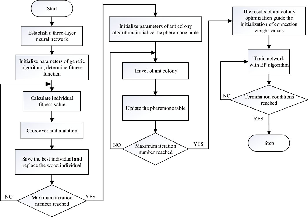
FIGURE 5. Algorithm flow chart.
5 Simulation results and analysis
MATLAB/Simulink is used to build the simulation model of the inverter, LabVIEW is used to collect the output current signal of the inverter and extract the features, and User Datagram Protocol is used for communication between them. The fault eigenvectors of 10 typical fault states of the inverters are selected as input data of the neural network. Fifty groups of data are collected for each fault state, and a total of 500 groups of data are used for network training and testing.
5.1 Simulation model
In order to demonstrate the method described in this paper, MATLAB/Simulink is used to build a three-phase inverter simulation model, as shown in Figure 6. The control mode is droop control, the modulation strategy is Space Vector Pulse Width Modulation, and its electrical parameters are shown in Table 4.
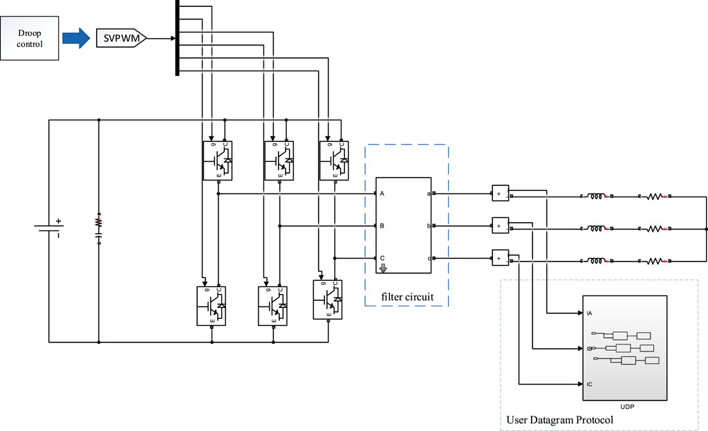
FIGURE 6. Three-phase inverter simulation model.
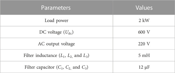
TABLE 4. Simulation parameters.
5.2 Network training
Based on the sample data, it is determined that there are 12 input nodes and 10 output nodes in the neural network. The number of hidden nodes is uncertain, and an appropriate number can be found according to Eq. 20. The Eq. 20 is an empirical formula.
where
Too few hidden nodes will lead to poor network performance, too many will lead to too long training time, trap in local optima, and overfit easily. Therefore, the number of hidden nodes should be determined by comprehensively considering the complexity and error of network, it should be as small as possible on the basis of meeting the accuracy requirements.
According to Eq. 20, the appropriate numbers of hidden nodes are 6, 7, 8, 9, 10, 11, and 12. The neural networks are respectively built and trained using BP algorithm under the same training samples. The percentage of classification error and MSE of each network are shown in Figure 7, so the number of hidden nodes is selected as 9.
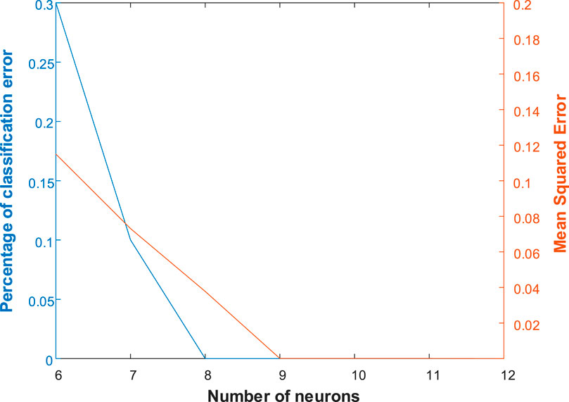
FIGURE 7. The relationship between the number of hidden nodes and classification error, MSE.
The number of input nodes, hidden nodes, and output nodes are 12, 9, and 10. The hidden layer uses the tansig function and the output layer uses the purelin function. There are 217 connection weights of neural network to be optimized. The interval [−10, 10] is equally divided into 100 parts. A number is randomly selected as candidate value in each cell. Finally, each connection weight to be optimized corresponds to a set of 100 candidate values. The initial chromosome of GA is composed of a candidate selected randomly from the set of candidate values for each parameter. After repeated matching and debugging, in the process of GA training, the population size and the number of iterations are finally selected as 100 and 300 respectively. In the process of ACO training, the ant population size, the evaporation coefficient
5.3 Analysis of simulation results
The proposed algorithm is run for ten times independently, where the mean, variance, maximum, and minimum values of MSE are 4.9819e-6, 5.4712e-10, 8.7457e-5, and 1.2686e-5, respectively. The experimental results show that the algorithm has good stability based on smaller means, variances, and extreme values. The predictive failure categories and actual categories of the test data are shown in Figure 8.
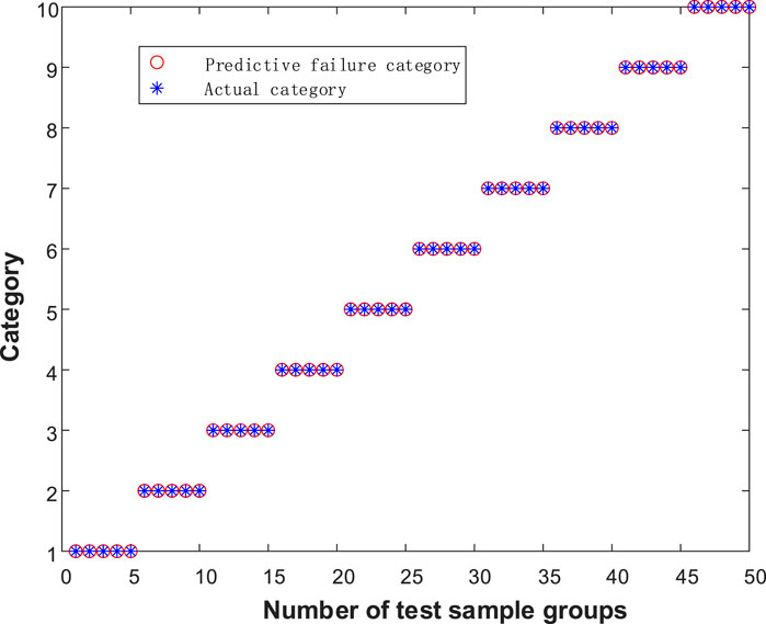
FIGURE 8. The predictive failure categories and actual categories of the test data.
In order to highlight the performance of the algorithm proposed in this paper, the training results of hybrid GA-BP algorithm, hybrid ACO-BP algorithm, and traditional BP algorithm under the same training samples and network architecture are added for comparative analysis. The RME decline curves of actual output and desired output are shown in Figures 9–12.

FIGURE 9. The training error of Traditional BP neural network.
FIGURE 10. The training error of GA-BP neural network.

FIGURE 11. The training error of ACO-BP neural network.
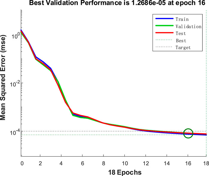
FIGURE 12. The training error of the evolutionary neural network.
It can be seen from Figure 8 that the trained evolutionary neural network can accurately classify test samples, and the fault extraction method and fault diagnosis algorithm proposed in this paper can effectively achieve accurate fault location. It can be seen from the comparison of Figures 9–12, the traditional BP neural network converges after 26 iterations, and the accuracy does not reach the predetermined value. The traditional BP neural network randomly assigns weights at the initial stage of training, so that it traps in local optima during the training process and occurs the problem of premature neuron saturation. This situation leads to the network training stopping before reaching the predetermined accuracy. GA-BP algorithm and ACO-BP algorithm converge after 30 and 26 iterations respectively, and the evolutionary neural network converges after 16 iterations, it is obvious that the evolutionary neural network has a faster convergence speed and smaller convergence error, because the evolutionary neural network introduces the crossover operator and mutation operator of GA and the ant colony tour of ACO during training, which expands the search space of the algorithm. The complementary advantages of GA and ACO improves the search ability and convergence speed, avoids trapping in local optima and improve the accuracy of the optimal solution.
6 Conclusion
Aiming at the characteristics of the increase of harmonic components and the loss of the positive and negative half waveforms of the output current in the inverter fault state, this paper proposed a feature extraction method based on FFT and average value on one cycle and an evolutionary neural network for fault diagnosis of three-phase inverter. The evolutionary neural network proposed in this paper combines the global search of GA and ACO with the local search of BP algorithm to obtain a more accurate combination of weight.
The joint simulation results of MATLAB/Simulink and LabVIEW show that the evolutionary neural network proposed in this paper is not easy to trap in local optima, has high learning accuracy and fast convergence speed, and is superior to the conventional neural network learning method in performance. Compared with traditional signal-based fault diagnosis methods, this method proposed in this paper can effectively resist noise interference and reduce the number of independent variables in the part of feature extraction, so that it can simplify the network model. In addition, this method can avoid the network training from trapping in local optima in the part of fault classification, with high accuracy and fast response speed. At the same time, it is mainly processed by software, which reduces the hardware cost, can realize precise location of the OC fault of one or two IGBTs of the inverter, can avoid the influences of noise, has fast response speed, and can be used for online monitoring.
Data availability statement
The original contributions presented in the study are included in the article/Supplementary Material, further inquiries can be directed to the corresponding authors.
Author contributions
HY wrote the main manuscript text. ZP provided the organization of the manuscript. TH prepared all the figures and tables. XZ collected references. QX performed the reference analysis and provided the research trends. All authors reviewed the manuscript.
Funding
This study is supported by a grant from Advanced Programs of Zhejiang Postdoctoral (ZX316000203).
Conflict of interest
The authors declare that the research was conducted in the absence of any commercial or financial relationships that could be construed as a potential conflict of interest.
Publisher’s note
All claims expressed in this article are solely those of the authors and do not necessarily represent those of their affiliated organizations, or those of the publisher, the editors and the reviewers. Any product that may be evaluated in this article, or claim that may be made by its manufacturer, is not guaranteed or endorsed by the publisher.
References
Ahmad, B., Amrr, S. M., Nabi, M., Khalid, M. R., and Jamil Asghar, M. S. (2021). “Analysis of three-phase grid-tied thyristor based inverter for solar PV applications,” in Proceedings of the 2021 International Conference on Sustainable Energy and Future Electric Transportation (SEFET), Hyderabad, India, January 2021 1–5. doi:10.1109/SeFet48154.2021.9375746
Bi, J. X., Hu, Z. L., Wang, Y., Li, H. B., and Wang, S. B. (2021). Reliability analysis of aeroengine blades based on fourier transform. IOP Conf. Ser. Mater. Sci. Eng. 1043 (2), 22041. doi:10.1088/1757-899x/1043/2/022041
Cai, B., Zhao, Y., Liu, H., and Xie, M. (2017). A data-driven fault diagnosis methodology in three-phase inverters for PMSM drive systems. IEEE Trans. Power Electron. 32 (7), 5590–5600. July. doi:10.1109/TPEL.2016.2608842
Cao, Q., Che, Y., Yang, J., Mi, M., and Men, Y. (2021). Short-circuit and open-circuit faults monitoring of IGBTs in solid-state-transformers using collector-emitter voltage. J. Power Electron. 21 (7), 1052–1060. doi:10.1007/s43236-021-00232-w
Guo, H., Sitton, G. A., and Burrus, C. S. (1998). The quick fourier transform: An FFT based on symmetries. IEEE Trans. Signal Process. 46 (2), 335–341. Feb. doi:10.1109/78.655419
Hongjiao, J. (2019). “Application of advanced BP neural network in image recognition,” in Proceedings of the 2019 18th International Symposium on Distributed Computing and Applications for Business Engineering and Science (DCABES), Wuhan, China November 2019 17–20. doi:10.1109/DCABES48411.2019.00012
Hu, Z-k., Gui, W-H., Yang, C-H., Deng, P-C., and Ding, S. X. (2011). Fault classification method for inverter based on hybrid support vector machines and wavelet analysis. Int. J. Control, Automation Syst. 9 (4), 797–804. doi:10.1007/s12555-011-0423-9
Ji, Z., and Liu, W. (2018). Open-circuit fault detection for three-phase inverter based on backpropagation neural network. Neural Comput. Appl. 31 (9), 4665–4674. doi:10.1007/s00521-018-3663-2
Khapre, S. P., Chopra, S., Khan, A., Sharma, P., and Shankar, A. (2020). “Optimized routing method for wireless sensor networks based on improved ant colony algorithm,” in Proceedings of the 2020 10th International Conference on Cloud Computing, Data Science and Engineering (Confluence), Noida, India, January 2020 455–458. doi:10.1109/Confluence47617.2020.9058312
Khomfoi, S., and Tolbert, L. M. (2007). Fault diagnostic system for a multilevel inverter using a neural network. IEEE Trans. Power Electron. 22 (3), 1062–1069. May. doi:10.1109/TPEL.2007.897128
Kou, L., Liu, C., Cai, G., Zhou, J., Yuan, Q., and Pang, S. (2020). Fault diagnosis for open-circuit faults in NPC inverter based on knowledge-driven and data-driven approaches. IET Power Electron. 13 (6), 1236–1245. doi:10.1049/iet-pel.2019.0835
Lambora, A., Gupta, K., and Chopra, K. (2019). “Genetic algorithm- A literature review,” in Proceedings of the 2019 International Conference on Machine Learning, Big Data, Cloud and Parallel Computing (COMITCon), Faridabad, India, February 2019 380–384. doi:10.1109/COMITCon.2019.8862255
Lei, M., Ren, X., and Fu, X. (2020). “Research on speed control strategy of permanent magnet synchronous motor based on BP-SSO-pid algorithm,” in Proceedings of the 2020 IEEE International Conference on Power, Intelligent Computing and Systems (ICPICS), Shenyang, China, July 2020 960–964. doi:10.1109/ICPICS50287.2020.9202199
Li, H., Yu, R., Yao, R., Wang, X., Li, J., Liu, R., et al. (2021). Optimization on thermomechanical behavior for improving the reliability of press pack IGBT using response surface method. IEEE J. Emerg. Sel. Top. Power Electron. 9 (5), 6329–6343. Oct. doi:10.1109/JESTPE.2021.3078891
Li, Y. W. (2020). An IGBT short-circuit protection method using variable VCE detection threshold. J. Phys. Conf. Ser. 1601, 22004. doi:10.1088/1742-6596/1601/2/022004
Ma, L., Huang, M., Yang, S., Wang, R., and Wang, X. (2022). An adaptive localize-d decision variable analysis approach to large-scale multiobjective and many-objective optimization. IEEE Trans. Cybern. 52 (7), 6684–6696. doi:10.1109/tcyb.2020.3041212
Ma, L., Li, N., Guo, Y., Huang, M., Yang, S., Wang, X., et al. (2021). Le-arning to optimize: Reference vector reinforcement learning adaption to constrained many-objective optimization of industrial copper burdening system. IEEE Trans. Cybern., 12698–12711. doi:10.1109/TCYB.2021.3086501
Ma, L., Wang, X., Wang, X., Wang, L., Shi, L., and Huang, M. (2021). Tcda: Truthful combinatorial double auctions for mobile edge computing in industrial internet of things. IEEE Trans. Mob. Comput. 21 (11), 1–4138. doi:10.1109/tmc.2021.3064314
Ma, L., Cheng, S., and Shi, Y. (2021). Enhancing learning efficiency of brain storm optimizati-on via orthogonal learning design. IEEE Trans. Syst. Man, Cybern. Syst. 51 (11), 6723–6742. Nov. doi:10.1109/tsmc.2020.2963943
Mohamed, M. I., El-Saady, G., and Yousef, A. M. (2021). “Performance analysis of genetic algorithm and ant colony optimization dependent on PID controller for matrix converter,” in Proceedings of the 2021 International Conference on Electronic Engineering (ICEEM), Menouf, Egypt, July 2021 1–6. doi:10.1109/ICEEM52022.2021.9480640
Phaneendra Babu, B., Srinivas, J., Vikranth, B., and Premchnad, P. (2008). “Fault diagnosis in multi-level inverter system using adaptive back propagation neural network,” in Proceedings of the 2008 Annual IEEE India Conference, Kanpur, India, December 2008 494–498. doi:10.1109/INDCON.2008.4768773
Tao, J., Wu, G., Yi, Z., and Zeng, P. (2021). “Innovative application of genetic algorithms in the computer games,” in Proceedings of the 2021 33rd Chinese Control and Decision Conference (CCDC), Kunming, China, May 2021 2197–2200. doi:10.1109/CCDC52312.2021.9601594
Wang, B., Li, Z., Bai, Z., Krein, P. T., and Ma, H. (2021). A voltage vector residual estimation method based on current path tracking for T-type inverter open-circuit fault diagnosis. IEEE Trans. Power Electron. 36 (12), 13460–13477. Dec. doi:10.1109/TPEL.2021.3087488
Yan, K., Chaojun, W. U., Liu, Z., and Qi, Z. (2021). Research on control strategy of three-phase inverter based on fractional calculus. J. Phys. Conf. Ser. 1754 (1), 12096. (8pp). doi:10.1088/1742-6596/1754/1/012096
Yang, N., and Shi, Y. (2019). “Research on tourist route based on a novel ant colony optimization algorithm,” in Proceedings of the 2019 IEEE International Conference on Power, Intelligent Computing and Systems (ICPICS), Shenyang, China, July 2019 160–163. doi:10.1109/ICPICS47731.2019.8942567
Keywords: converter, three-phase inverter, evolutionary neural network, fast Fourier transform, fault diagnosis
Citation: Yang H, Peng Z, Xu Q, Huang T and Zhu X (2023) Inverter fault diagnosis based on Fourier transform and evolutionary neural network. Front. Energy Res. 10:1090209. doi: 10.3389/fenrg.2022.1090209
Received: 05 November 2022; Accepted: 30 December 2022;
Published: 19 January 2023.
Edited by:
Lianbo Ma, Northeastern University, ChinaReviewed by:
Nan Li, Northeastern University, ChinaJing Zhang, North University of China, China
Zhenshou Song, Xidian University, China
Copyright © 2023 Yang, Peng, Xu, Huang and Zhu. This is an open-access article distributed under the terms of the Creative Commons Attribution License (CC BY). The use, distribution or reproduction in other forums is permitted, provided the original author(s) and the copyright owner(s) are credited and that the original publication in this journal is cited, in accordance with accepted academic practice. No use, distribution or reproduction is permitted which does not comply with these terms.
*Correspondence: Zishun Peng, MTI0MzEyNzM5M0BxcS5jb20=; Xiangou Zhu, emh1eG9Ad3p1LmVkdS5jbg==
†These authors have contributed equally to this work and share first authorship