 Jian Feng Zhao
 Qian Chao Liang
- College of Power Engineering, Naval University of Engineering, Wuhan, China
Ammonia can be stored as a liquid under relatively easy conditions (Ambient temperature by applying 10 bar or Ambient pressure with the temperature of 239 K). At the same time, liquid ammonia has a high hydrogen storage density and is, therefore, a particularly promising carrier for hydrogen storage. At the same time, the current large-scale industrial synthesis of ammonia has long been mature, and in the future, it will be possible to achieve a zero-emission ammonia regeneration cycle system by replacing existing energy sources with renewable ones. Ammonia does not contain carbon, and its use in fuel cells can avoid NOx production during energy release. high temperature solid oxide fuel cells can be directly fueled by ammonia and obtain good output characteristics, but the challenges inherent in high temperature solid oxide fuel cells greatly limit the implementation of this option. Whereas PEMFC has gained initial commercial use, however, for PEMFC, ammonia is a toxic gas, so the general practice is to convert ammonia to pure hydrogen. Ammonia to hydrogen requires decomposition under high temperature and purification, which increases the complexity of the fuel system. In contrast, PEMFC that can use ammonia decomposition gas directly can simplify the fuel system, and this option has already obtained preliminary experimental validation studies. The energy efficiency of the system obtained from the preliminary validation experiments is only 34–36%, which is much lower than expected. Therefore, this paper establishes a simulation model of PEMFC directly using ammonia decomposition gas as fuel to study the maximum efficiency of the system and the effect of the change of system parameters on the efficiency, and the results show that the system efficiency can reach up to 45% under the condition of considering certain heat loss. Increasing the ammonia decomposition reaction temperature decreases the system efficiency, but the effect is small, and the system efficiency can reach 44% even at a temperature of 850°C. The results of the study can provide a reference for a more scientific and quantitative assessment of the potential value of direct ammonia decomposition gas-fueled PEMFC.
Introduction
Ammonia can be stored as a liquid under relatively easy conditions [Ambient temperature by applying 10 bar (Aziz et al., 2020) or Ambient pressure with the temperature of 239 K (Iverson et al., 2018)]. Liquid ammonia has a high hydrogen storage density, 17.8 wt% by mass and 121 Kg H2 m−3 by volume, so it is a particularly promising hydrogen storage carrier. The large-scale industrial synthesis of ammonia has long been mature, and in the future, it can also be used to achieve zero-emission renewable energy cycle storage systems through renewable energy sources (Cinti et al., 2020). Currently, facilities for ammonia transportation and storage exist in society, so it can be easily and economically transported to its destination (Mckinlay et al., 2021). Ammonia contains no elemental carbon and therefore has no carbon emissions. The synthesis of ammonia requires nitrogen and hydrogen. Nitrogen can be obtained in large quantities from the air, hydrogen can be obtained from the electrolysis of water, and ammonia is regenerated into nitrogen and water in the process of releasing energy, so the whole process can achieve harmless emissions (Yapicioglu and Dincer, 2019). The electrochemical synthesis of ammonia at low temperature and low pressure is also being studied in recent years (Lu et al., 2018; Garagounis et al., 2019). Therefore the construction of an ammonia-based zero-emission renewable energy system has a good prospect.
Ammonia does not contain carbon and therefore has no carbon emissions, but the use of ammonia by direct combustion can lead to the generation of NOx, which can cause damage to the environment (Naha et al., 2019). In contrast, the use of ammonia in fuel cells avoids the generation of NOx. For indirect ammonia fuel cells, ammonia is first converted to nitrogen and hydrogen under medium temperature conditions, thus avoiding the generation of NOx. For direct ammonia fuel cells, even for high-temperature solid oxide fuel cells (SOFC), the operating temperature is 700–800°C, which is far below the NOx generation temperature (Wu, et al., 2020), and relevant studies have demonstrated that SOFC can avoid NOx generation when using ammonia as fuel (Barelli et al., 2020; Ni et al., 2010).
Although high temperature solid oxide fuel cells (SOFC) can directly use ammonia as fuel (Hashinokuchi et al., 2018; Okanishi et al., 2017; Zeng et al., 2020), SOFC is still in the research and development stage, with disadvantages such as start-up time, low lifetime, and high cost, and has not yet entered commercial applications. In contrast, the proton exchange membrane fuel cell (PEMFC) has already gained initial commercial application and has made significant progress in terms of start-up time, lifetime, and cost (Wang et al., 2019). Therefore, the use of ammonia gas as the hydrogen storage medium for PEMFC is gradually attracting attention.
Since ammonia can poison the acidic proton exchange membrane and the cathode catalyst (Imamura et al., 2011; Lopes et al., 2014), PEMFC is very sensitive to ammonia. The residual amount of ammonia in the fuel should be less than 0.1 ppm (Miyaoka et al., 2018), so ammonia cannot be used directly in PEMFC. The current method is to convert ammonia into pure hydrogen, so the whole power generation system contains the following subsystems: decomposition of ammonia, purification of hydrogen, fuel cell, etc.(Araya et al., 2016). Alessandra Perna et al.(Perna et al., 2020)studied a distributed on-site hydrogenation system based on ammonia supply from an energy and economic point of view. The system’s core is a hydrogen production system containing an ammonia cracking reactor and its auxiliary equipment. The electrical energy demand (i.e., hydrogen compression and cooling) necessary for the power station’s operation is met by a PEMFC power module. The energy performance was evaluated based on the daily demand of hydrogen, and the balance cost of hydrogen was estimated. Kyunghwa Kim et al. (Kim et al., 2020) investigated the economics and environmental friendliness of ammonia-fueled PEMFC propulsion systems for a 2,500 Twenty-foot Equivalent Unit (TEU) container feeder ship demand. Li et al. developed a physicochemical system model of a 300 Nm3 h−1 on-site ammonia hydrogen production station based on experiments. They analyzed the efficiency and hydrogen production capacity of eight H2 purification subsystems (Lin et al., 2020).
At present, the research hotspots of ammonia-fueled PEMFC systems focus on the efficient decomposition of ammonia and the on-site purification of hydrogen. The research on the efficient decomposition of ammonia includes the study of efficient catalysts (Fujitani et al., 2020; Sayas et al., 2020), microfluidic reactors (Kim and Kwon, 2011), and process optimization (Badescu, 2020). For catalysts, Ni-loaded catalysts with Al2O3 are still the most stable, economical, and efficient catalysts for ammonia decomposition. Although various combinations of Ru can obtain better results, they are less durable and cannot work for a long time, and Ru is a precious metal, which is not very economical. The microfluidic reactor can significantly enhance the heat transfer between the reaction unit and the heating unit and improve the reactor’s volumetric hydrogen production rate and energy utilization efficiency. The process optimization study includes the study of the reaction mechanism and the optimization of the reactor boundary conditions (e.g., geometry configuration, heating conditions, etc.), which can provide a reference for developing more efficient catalysts and reactor structures.
Research on hydrogen purification includes variable pressure adsorption (Zhang et al., 2021), deep cold adsorption (Aasadnia et al., 2021), and membrane separation technology (Iulianelli et al., 2019). Compared with VPS and membrane separation technologies, deep-cooled adsorption requires a large amount of energy to maintain low temperatures and is only suitable for large-scale production. The hot spots of research on hydrogen separation in small-scale on-site hydrogen production are mainly variable pressure adsorption and membrane separation technologies. Currently, large-scale VPS equipment can achieve a 90% hydrogen recovery rate. Still, for small-scale on-site hydrogen production scenarios, there are problems of large equipment systems and high inlet pressure (Lin et al., 2020). Membrane separation technology can reduce the size of separation equipment and is, therefore, a potential solution for hydrogen separation in small-scale on-site hydrogen production systems. Current selective separation membranes can be divided into two categories: first, metallic membranes, mainly palladium membranes, with high permeability and selectivity, suitable for high-purity hydrogen production but expensive. Dolan et al. have developed tubular palladium-coated vanadium membranes. The developed membranes exhibit high permeability (above 3.0 × 10⁻⁷ mol/ms·Pa0.5at temperatures above 320°C) and robustness. Furthermore, vanadium is a relatively inexpensive material, the separation cost of such membranes is lower compared to single Pd-based membranes (Dolan et al., 2018); secondly, polymer membranes are cheap but have lower permeability and selectivity and are not suitable for ultra-high purity hydrogen production (Galizia et al., 2017). In recent years, it has been shown that combining a variable pressure adsorption device with membrane separation is expected to obtain a high recovery and economical method for high-purity hydrogen production, which can solve the problem of high-purity hydrogen separation for small-scale on-site hydrogen production systems (Lin et al., 2020; Li et al., 2016).
In conclusion, the purification technique of hydrogen requires complex equipment, which is very unfavorable for small on-site hydrogen production scenarios. The strategy of feeding the ammonia decomposition gas, which has undergone residual ammonia removal, directly to the PEMFC will significantly simplify the system (referred to as ADG-PEMFC in this paper). In this regard, some scholars have already started to conduct preliminary studies. Alagharu et al. (Alagharu et al., 2010) analyzed a 100 W ADG-PEMFC system with an electrically heated ammonia decomposer as a component. The system’s total output power was 142 W, the ammonia flow rate was 0.0009 mol/s, and the efficiency was 35%. Hunter et al. established an ADG-PEMFC demonstration platform based on an ammonia decomposer heated by ammonia catalytic combustion. They demonstrated the feasibility of ADG-PEMFC, but the energy efficiency obtained was only 34% (Hunter et al., 2016). Cha et al. (Cha et al., 2018) established a 1 kW ADG-PEMFC demonstration system, and the heat required for the ammonia decomposer reaction was provided by isobutane combustion, and the system efficiency obtained was about 32–36%. The simulations showed that the system efficiency could reach 49% when the fuel cell anode tail gas reuse was considered.
The efficiency of the existing experimental system is much lower than that of the fuel cell, and it is difficult to reflect the advantages of ammonia, so it is necessary to conduct in-depth research and analysis on the ideal efficiency of the system and related factors. This paper establishes an ADG-PEMFC simulation model to study and analyze the maximum efficiency of the system and the effect of changes in system parameters on the efficiency so that the potential value of ADG-PEMF can be quantitatively evaluated more scientifically.
System Structure and Procedure
The system structure and process are shown in Figure 1. Firstly, the ammonia gas is evaporated and preheated through the Evaporator and Recuperator 1. It enters Recuperator 2 to raise the required temperature for the decomposition reaction. It then enters the Cracker for catalytic decomposition, the decomposition gas is cooled through the Recuperator 1 and Evaporator, and at the same time, it provides energy for the gasification and preheating of liquid ammonia. Because the latent heat of gasification of liquid ammonia is large, theoretically, it can cool the high-temperature decomposition gas to the same temperature. After that, the decomposition gas enters the Absorber to remove the residual ammonia and obtain a pure hydrogen-nitrogen mixture (crude hydrogen), which is sent to the PEMFC for electrochemical reaction to generate electric energy, and then the anode exhaust gas enters the Combustor to generate high-temperature gas by catalytic combustion with air. The high-temperature gas is sent to the Cracker to provide the required energy for the ammonia decomposition reaction. It then flows through Recuperator 2 and Recuperator 3 to heat the ammonia entering the Cracker and the air and fuel entering the Combustor, respectively. When the high-temperature gas generated by the anode tail gas alone cannot meet the heat demand of the ammonia decomposition reaction, additional energy will be added to the Combustor by adding additional ammonia gas and corresponding air.
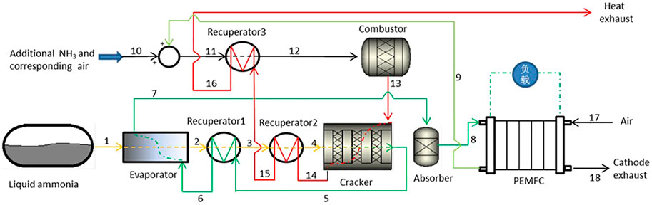
FIGURE 1. System structure and procedure.
System Modeling
The links in the system can be categorized as the Evaporator module, Recuperator module, Cracker module, Absorption module, Combustor module, and the PEMFC module. Also, to simplify the model, the following assumptions are made:
1) Ignore the pipeline heat loss and resistance loss, so the fluid thermal parameters on the pipeline between modules do not change. In this paper, the pipelines between modules in the system are numbered to identify the gas status parameters of each module.
2) The heat loss of each module of the system is considered and expressed as the ratio of the heat transferred in the module to the max total heat that can be provided by the high-temperature heat source in the module.
Evaporator and Recuperator 1 Modeling
The role of the Evaporator and the Recuperator 1 is to use the waste heat of the high-temperature ammonia decomposition gas to gasify and preheat the liquid ammonia. Since this is a continuous process, the two modules are modeled together in this paper.
According to the conservation of energy:
Where, ci the constant pressure specific heat capacity of the gas (unit: J/(mol-K)), Gi is the gas flow rate (unit: mol/s), γ is the latent heat of gasification of liquid ammonia (unit: J/mol), ηex1 is the heat transfer efficiency of the Evaporator and the Recuperator 1, which is equal to the product of the heat transfer efficiency of the Evaporator and the Recuperator 1, i = 1,2,…,n.
Since in the Recuperator 1, the substance of the low-temperature fluid is NH3, and the substances of the high-temperature fluid include NH3, N2, and H2, the constant pressure specific heat capacity and flow rate of different substances are not the same, so for Eq. 1 needs to be further modified as:
Due to the following relationship between the molar flow of substances for low-temperature fluids and high-temperature fluids:
Where x is the decomposition rate of ammonia, substituting Eqs 3–5 into Eq. 2 yields:
At constant pressure, the approximate relationship between specific heat capacity and temperature can be expressed as follows:
The parameters corresponding to the group elements involved in this paper are shown in Table 1 (Kyle, 1984).
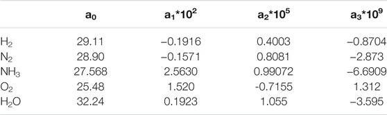
TABLE 1. Specific heat of air (
Equation 7 shows that the constant pressure specific heat capacity is a function of temperature, so Eq. 6 needs to be changed to an integral form as follows:
Recuperator 2 Modeling
The role of the Recuperator two is to use high-temperature gas to preheat ammonia to the temperature required for the decomposition reaction, the substance of the low-temperature fluid is NH3, and the substances of the high-temperature fluid include O2, N2, H2O. With reference to formula (2), the conservation of energy equation for the Recuperator two is shown below:
where ηex2 is the heat transfer efficiency of the Recuperator 2.
Recuperator 3 Modeling
The role of Recuperator 3 is to use the waste heat of high-temperature gas to heat the fuel and air entering the combustor, which is the same as the role of micro gas turbine’s Recuperator (McDonald, 2000). “Regenerator effectiveness” is used to calculate the thermal parameters of Recuperator 3 refer to the thermal calculation of micro gas turbine’s Recuperator.
Regenerator effectiveness The ratio of the actual heat absorbed by the low-temperature fluid in the recuperator to the maximum heat released to the low-temperature fluid from the high-temperature fluid under ideal conditions in the recuperator.
Where cp,c is the heat capacity at a constant pressure of low-temperature fluid (SI unit: J/(mol*k)), cp,h is the heat capacity at a constant pressure of high-temperature fluid (SI unit: J/(mol*k)), Tc,out, Tc,in is the outlet and inlet temperature of the low-temperature fluid (SI unit: k), Th,out, Th,in is the outlet and inlet temperature of the high-temperature fluid (SI unit: k).
Assumption cp,c = cp,h (McDonald, 2000), Eq. 1 can be rewritten as:
Under the rated condition, the regenerator effectiveness can generally be set as 0.9. For counter-flow heat exchanger, the regenerator effectiveness under partial operating conditions is
Where α0 is the regenerator effectiveness of rated condition, qr is the actual flow rate, q0 is the rated flow rate (SI unit: L/min).
Since the recuperator is not ideally adiabatic in the heat transfer process, the recuperator also exchanges heat with the external environment. This loss is mainly determined by the external environment. It can be assumed that the heat loss from the recuperator to the external environment remains constant and independent of the operating conditions. The heat loss rate δ at the rated state can be taken as 2% in a standard environment.
The outlet temperature of low-temperature fluid:
From Eq. 13, the inlet and outlet temperature model of heat exchanger 3 can be obtained as:
Cracker Modeling
The ammonia cracker contains two critical links: the decomposition of ammonia and the energy transfer between the heating gas and the reaction gas. And the two links are coupled with each other. The decomposition of ammonia gas involves chemical reaction kinetics, molecular diffusion kinetics, and fluid mechanics, while the energy transfer involves heat transfer and fluid mechanics. Since the goal of the study in this paper is the overall ideal performance of the system, therefore, assuming that the reactor can ensure that the ammonia decomposition reaction reaches the equilibrium state, ignore the influence of molecular diffusion as well as fluid flow on the decomposition reaction, and only consider the chemical reaction kinetics and heat transfer. Then the cracker model can be separated into two submodules, one for the decomposition reaction of ammonia gas and one for the heat transfer between hot and cold fluids. The two submodules are linked together by energy conservation.
The decomposition reaction of ammonia will absorb a lot of heat, so increasing the reaction temperature will significantly promote the decomposition reaction of ammonia. The reaction of ammonia decomposition is as follows:
The initial reactants are only NH3, and the pressure in the Plug flow reactor is a constant value P. The reaction rate of ammonia gas decomposition is x.
Table 2 shows the component changes during the decomposition reaction. The state point I is the reactor inlet and the state point II is the reactor outlet.
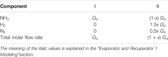
TABLE 2. Molar flow rate values for each component during the decomposition reaction.
Because it is a plug flow reaction, it can be regarded as a constant pressure reaction, the equilibrium partial pressure of each component at state point II is as follows:
This leads to the equilibrium constant of the decomposition reaction Keq:
The equilibrium constant is a function of temperature and pressure. Since the pressure in the system is atmospheric, the effect of pressure is not significant, so the effect of pressure on the equilibrium constant is ignored, and according to the law of thermodynamics, the equilibrium constant can be expressed as:
Where
The enthalpy and entropy values of the gas at temperature T0 are shown in Table 3 (Wark, 1977).
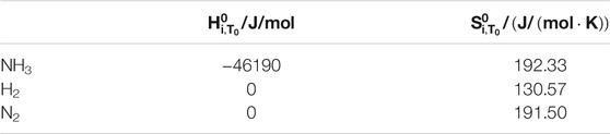
TABLE 3. Enthalpy and entropy (T0 = 298.13 K).
In the case of constant pressure, the approximation of specific heat capacity versus temperature can be expressed as Eq. 7, The parameters corresponding to the components involved in this paper are shown in Table 1.
The energy absorbed by the decomposition reaction is
For high-temperature gases that provide heat for the decomposition reaction, the heat released is calculated as follows:
Where ηex3 is the heat transfer efficiency of the decomposer. According to the second law of thermodynamics, the outlet temperature of the heat source fluid must not be lower than the inlet temperature of the reactants. If it is not satisfied, the inlet temperature of the heat source fluid is increased by adding supplementary combustion ammonia and recalibrating the calculation.
Ammonia Absorption Moduling
In this paper, porous material adsorption is used to absorb residual ammonia, so the main effects on the absorption process are flow resistance loss, mass loss, and energy consumption for adsorbent regeneration.
1) Mass loss
Where λ is the absorption rate of ammonia, because after purification, the content of ammonia is extremely low and can be approximated as λ = 1.
2) Energy consumption
The energy loss in the separation process of ammonia is mainly due to the additional energy consumed for the regeneration of the adsorbent, which can be averaged over a complete working cycle. Therefore the energy loss can be simply expressed as a linear relationship.
Where w is the regeneration energy consumption constant [SI unit:J/(s*L)], which equal to the ratio of the energy consumed by the regeneration of the adsorbent to the mass of absorbed ammonia in one cycle.
PEMFC Moduling
The conventional PEMFC modeling approach is based on the fuel cell electrochemical reaction model, flow, diffusion, and heat transfer theory. The empirical parameters in the model are then corrected based on experimental data to achieve better modeling accuracy. However, the output characteristics of the cell are affected by both current and fuel flow when crude hydrogen is used as fuel, which leads to difficulties in the above modeling method. Therefore, this paper uses interpolation through experimental data to obtain the PEMFC module power, efficiency, and relevant output parameters. Figure 2 shows the experimental data of PEMFC obtained by the experiment.
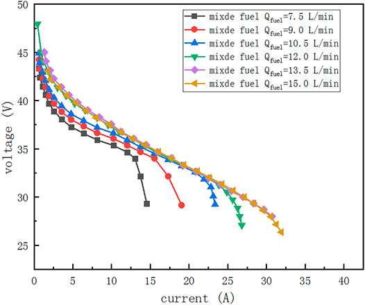
FIGURE 2. Voltage-current characteristic curve of PEMFC under different crude hydrogen flow rates.
Combustor Moduling
In this paper, since only the system characteristics in the ideal state are discussed, the complex mass transfer process, heat transfer process, and chemical reaction process involved in catalytic combustion are not considered, and the gas temperature is theoretically related only to the state of the inlet and outlet substances, independent of other factors. Therefore the exit temperature of the combustion chamber can be obtained by the energy conservation of the inlet and outlet substances in the catalytic combustion chamber. In the combustion chamber, the following reactions mainly occur.
The chemical reaction Equations 31, 32 are unfavorable side reactions of ammonia combustion because NOx is generated. Li et al. (Li et al., 2014) investigated the generation of NOx during the eruption of ammonia. It showed that when the NH3-H2 fuel mixture containing 50% ammonia was combusted at an excess air coefficient of 1.25, the detected amount of NOx in the resulting gas was 1,200–1300 PPM, while the amount of NOx detected in the gas generated from pure hydrogen fuel at the same excess air coefficient is 650 PPM. It means that some ammonia undergoes chemical reactions (31) and (32), but its reaction amount is not high. The results of also showed that increasing the excess air coefficient and ammonia content would reduce the total NOx production. In this paper, the excess air coefficient is set to 1.3, so the amount of ammonia involved in the chemical reactions 31 and 32 can be considered negligible for the thermal calculations. Therefore, to simplify the model, the following assumptions are made.
1) The degree of reaction of combustible gases in the combustion chamber is close to 100%, the values of which are shown in the following table of simulation parameters, ignoring the influence of unreacted gas on the thermal parameters of the mainstream gas.
2) Neglecting the side reactions of ammonia combustion.
3) The heat loss transferred from the combustion chamber to the environment is reflected by the insulation efficiency of the combustion chamber.
According to the conservation of energy
Where ηcom is the combustion efficiency of combustibles and ηie is the insulation efficiency of the combustion chamber. The enthalpy of gas ΔHi can be calculated by Eq. 23.
Results and Discussion
Analysis of the Influence of Ammonia Decomposition Temperature and PEMFC Current on the System
Table 4 shows the initial system parameters. The ammonia decomposition temperature and the current of the PEMFC are critical operating parameters of the system, and both affect the system’s efficiency. Figure 3 shows the efficiency of the system at different temperatures and currents. According to the current of PEMFC, the value of system efficiency with temperature can be divided into three intervals. When the current is in the interval of 0–19 A, the temperature has little effect on the system efficiency. When the current is in the interval of 19–26.5 A, the system efficiency increases and then decreases with temperature, but the decrease is tiny. The system efficiency decreases sharply at the low-temperature end when the current is greater than 26.5 A. The reason for this phenomenon can be further analyzed by Figure 4. In the low current interval, the remaining hydrogen in the anode is more, which can provide sufficient energy for the ammonia decomposer, as shown in curves 4/5/6 of Figure 4, so the ammonia flow rate of the supplemental combustion is zero. And at this time, the fuel in the PEMFC is sufficient, and the PMEFC working current is in the ohmic polarization interval. Hence, the PEMFC output power corresponding to different ammonia decomposition temperatures is the same under the same current, as shown in curve 1/2/3 of Figure 4. Therefore, the system efficiency does not change with the reaction temperature. Increasing the current of PEMFC, different phenomena appear at the two ends of the reaction temperature, firstly, the low-temperature end, at the lower decomposition temperature due to the significant reduction of ammonia decomposition rate, the residual undecomposed ammonia greatly increased, resulting in the final total amount of fuel into the PEMFC is reduced, according to the experimental results in Cracker Modeling, it is known that the current of PEMFC has entered the concentration polarization influence region at this time. Therefore, the output power of PEMFC decreases significantly, as shown in curve 7. At the same time, because the tail gas of the anode cannot provide enough energy for the decomposer, it has to supplement the ammonia gas for the combustion chamber, which further leads to the decrease in the efficiency of the system, as shown in the curve eight of Figure 4. And at the high-temperature end, more supplemental combustion ammonia gas is also required because of the higher reactor decomposition temperature. Meanwhile, in the high-temperature end region, the decomposition rate of ammonia is high at this time, and the change with temperature is yet small, the fuel in the PEMFC is still sufficient, the PMEFC operating current is still in the ohmic polarization region, and the output power of the PEMFC is basically the same, so the system efficiency decreases slowly due to the increase of the additional fuel. Finally, when the operating current of PEMFC is further increased, at this time, at all temperatures, the operating current of PEMFC enters the region affected by the dense differential polarization, resulting in a sharp drop in the output power of PEMFC and a significant decrease in system efficiency.
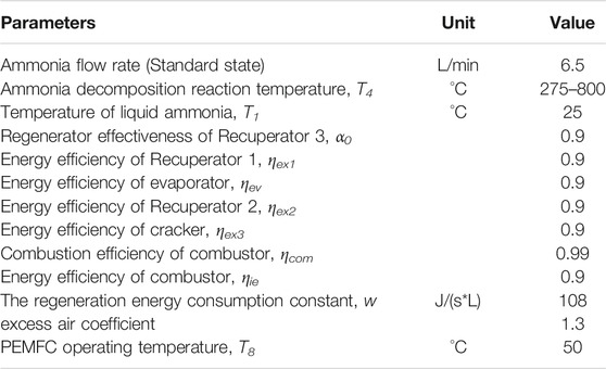
TABLE 4. System parameters.
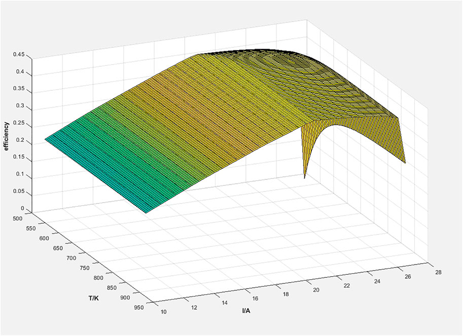
FIGURE 3. The efficiency of the system at different temperature and current.
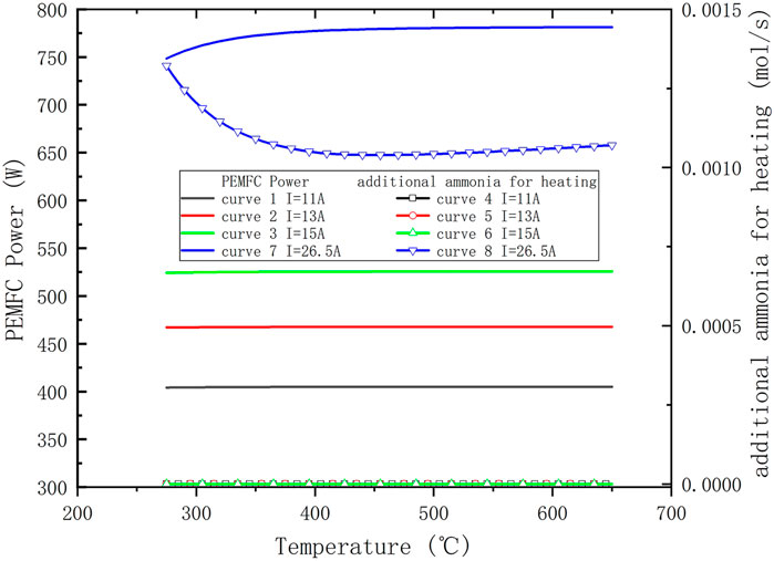
FIGURE 4. Variation of PEMFC power and amount of additional fuel with temperature at different current.
Figure 5 shows the system’s maximum efficiency of different reaction temperatures and the corresponding fuel utilization rate, working current value. From the Fuel utilization curve and the Current curve in the figure, it can be seen that both the working current and the fuel utilization rate vary very little, with the variation range of the current being 20–21 A and the variation range of the fuel utilization rate being between 0.72 and 0.77. The efficiency curve shows that although the system efficiency varies greatly at the low reaction temperature end when the reaction temperature of the system exceeds 340°C, the highest efficiency is obtained at a temperature of 418°C with a value of 45.02%, and the lowest efficiency is obtained at a temperature of 650°C with a value of 44.53%, which is only a 0.5% decrease inefficiency. This is a magnificent phenomenon for the ADG-PEMFC system. Because in the actual system, the rate of ammonia decomposition and the volume of the decomposer are limited, a reaction temperature higher than 600°C is often required to achieve a high rate of ammonia decomposition. The above simulation results show that a significant increase in the reaction temperature has less impact on the system efficiency. Still, of course, this conclusion is without considering the impact of the increase in reaction temperature on the radiation heat loss.
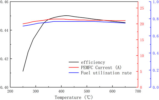
FIGURE 5. The system’s maximum efficiency of different reaction temperatures and the corresponding fuel utilization rate, working current value.
Effect of Current on System Characteristics
The operating temperature of the Cracker in the system is set to 650°C in this paper. Figure 6 shows the variation of system efficiency, additional fuel quantity, and PEMFC output power with the current. The system efficiency increases linearly with the change of current at the initial stage, and the system reaches the highest efficiency point when the current is 20.9 A. After that, the system efficiency starts to decrease slowly with the increase of current, and finally, the system efficiency drops sharply when the current exceeds 26.5 A. The change of the power curve of PEMFC and the change of the charge fuel flow curve correspond to the analysis results in 4.1. From the fuel replenishment curve in the figure, it can also be seen that the current corresponds to the maximum efficiency (referred to as critical current in this paper) is at the point where the fuel in the tail gas of the PEMFC is just enough to provide the energy required for ammonia reforming. Figure 6 also shows that the highest system efficiency point a is not at the same location as the highest PEMFC efficiency point b. The output power of the PEMFC at point a is less than that at point b, which means that more fuel is reserved to supply the combustor.
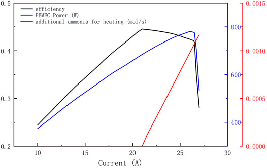
FIGURE 6. The variation of system efficiency, additional fuel quantity, and PEMFC output power with current.
Energy Flow Distribution at the Highest Efficiency Point
The final distribution of the energy input into the system is mainly the heat loss from the individual modules, the electrical energy generated by the PEMFC, and the exhaust gas. Figure 7 shows the percentage of energy lost from each module in the system and the electrical power generated by the PEMFC to the total input energy at the ammonia decomposition reaction temperature of 650°C and the PEMFC current of 20.9, respectively. From the figure, it can be seen that the main energy distribution in the system is the electrical energy generated by PEMFC (44.52%), the PEMFC heat loss (41%), and the waste heat loss of exhaust gas (6.9%). For the waste heat loss of the exhaust gas, the exit temperature of the exhaust gas is only 365.2 K at this time, so the quality of the remaining heat is also low, and there is a serious difficulty in continuing to improve the efficiency of waste heat utilization. Improving the power generation efficiency of PEMFC and reducing the heat loss of PEMFC is an effective way to improve the system efficiency. A three-dimensional simulation study of a PEMFC fueled by a nitrogen-hydrogen mixture shows that the efficiency of the PEMFC can be improved by 3–5% through geometry optimization. For PEMFC heat loss, the key factor is the maximum operating temperature of PEMFC, so this loss can be reduced by improving the high-temperature resistance of PEMFC.
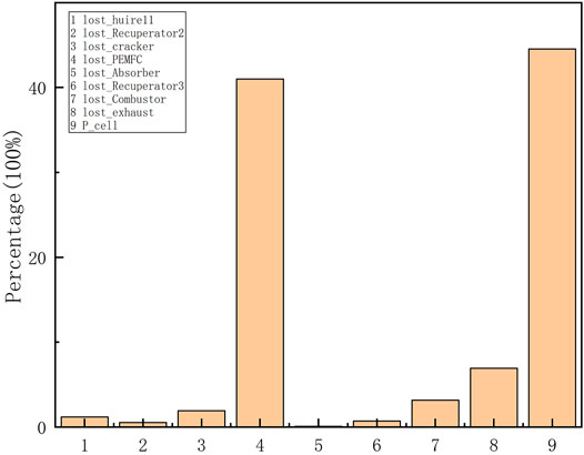
FIGURE 7. System energy distribution diagram.
Effect of PEMFC Operating Temperature on System Efficiency
The effect of PEMFC efficiency on system efficiency is a linear and explicit effect, and the amount of system efficiency improvement is equal to the amount of PEMFC efficiency increase while keeping other conditions constant. However, the increase in PEMFC operating temperature has an implicit effect on the system efficiency. The impact of the increase in operating temperature on the efficiency is twofold: first, the anode tail gas contains higher thermal energy, which reduces the heat loss of the PEMFC; second, the higher thermal energy in the anode tail gas increases the critical current value, which makes the PEMFC generate more power. Table 5 shows the assumed maximum system efficiency, corresponding PEMFC power, and current values at different PEMFC operating temperatures. It should be emphasized that the maximum operating temperature of the current PEMFC is generally not higher than 80°C, and the simulation data in the table with an operating temperature greater than 80°C is for the medium-temperature PEMFC that may gain application in the future. It can be seen from Table 5 that the significant increase in the operating temperature of the PEMFC does not result in a significant increase in the efficiency of the system, probably because the ADG-PEMF system in this paper only considers the anode when recovering the waste heat from the PEMFC tail gas, and in fact, most of the waste heat from the tail gas is taken away by the cathode gas, so that increasing the operating temperature of the PEMFC has little effect on the efficiency of the system.
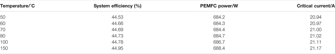
TABLE 5. Output characteristics of the system at different PEMFC operating temperatures.
Effect of Anode Tail Gas Energy Utilization on System Efficiency
The analysis results in Effect of Current on System Characteristics show that when the system works at the maximum efficiency point, the heat required for the ammonia decomposition reaction is completely provided by the fuel of the anode tail gas, so the anode tail gas energy utilization must have a significant influence on the system efficiency, so this paper investigates the influence of the anode tail gas energy utilization on the maximum efficiency of the system, and the anode tail gas energy utilization is expressed by the insulation efficiency ηie of the combustion chamber. The simulation results shown in Figure 8 show that ηie has an important influence on the system coefficient, and the maximum efficiency of the system is only 40% when ηie is 0, while the system efficiency is 44.5% when ηie is 0.9. And the figure also shows that the system critical current is also influenced by ηie. When ηie is low, there is no critical current. As ηie increases, the critical current appears. And the critical current value increases as ηie increases.
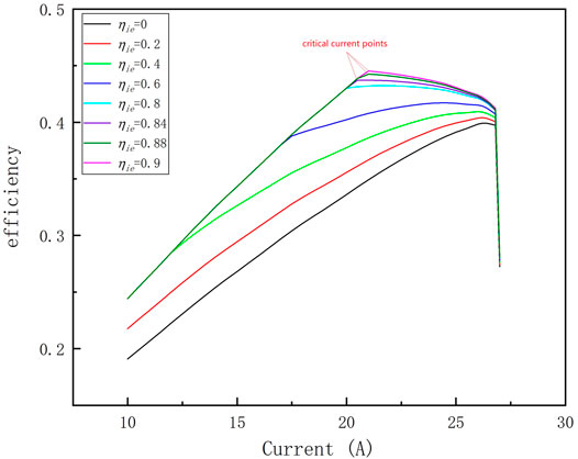
FIGURE 8. Output characteristics of the system under different ηie.
Study of System Efficiency at an Experimental Ammonia Decomposition Rate
Figure 9 shows the results of ammonia decomposition rate with decomposition temperature obtained experimentally in this paper, the experimental device is a tubular reactor with external electric heating, 800 mm in length and 20 mm in inner diameter, filled with NiO-AL2O3 catalyst particles (NiO≥14.0wt%), the porosity of catalyst is 0.47, and the filling amount of catalyst is 250 g. It can be seen from the figure that the experimental ammonia reaction temperature needs to be greater than 760°C to obtain greater than 90% ammonia decomposition rate, so the temperature of the ammonia decomposition reaction was set to be 760–800°C. Figure 10 shows the maximum efficiency of the ADG-PEMF at different ammonia decomposition reaction temperatures, corresponding current values, and additional fuel flow rates obtained based on the ammonia decomposition experimental data. From the efficiency curves, it can be seen that the system obtains a maximum efficiency value of 44.05% at the point of 830°C and 20.59 A, which is a small decrease in efficiency compared to the results of 4.1 and 4.2. And it can be seen from the current curve versus the additional fuel flow curve that the critical current disappears when the decomposition rate of ammonia is low. The reason is that the decomposition rate of ammonia is insufficient, which leads to the need for re-fueling to obtain a higher system efficiency, which corresponds to a lower limit of the decomposition rate of 0.97 under the parameters set in this paper. The efficiency curve of the system shows that the system with a critical current will have a higher system efficiency. Also there is a deep in current at 790°C, the reason is that influenced by the ammonia decomposition rate, the fuel entering the PEMFC is significantly reduced before 790°C due to the low decomposition rate of ammonia. And as we can see from the ammonia decomposition rate curve, the slope of the curve at 790°C is also large, so the efficiency of the system at this time is affected by both the PEMFC power and the additional fuel, and the effect of the additional fuel is greater than the effect of the PEMFC power, and the only way to reduce the additional fuel is to increase the amount of fuel in the PEMFC anode tail gas, so a certain amount of PEMFC power output needs to be sacrificed (i.e. lower operating current) to ensure that the system obtains higher efficiency. After 790°C, the decomposition rate of ammonia is high enough that it is no longer a major influence, and the system enters a state with critical current at this time, so the current corresponding to the highest efficiency is the critical current.
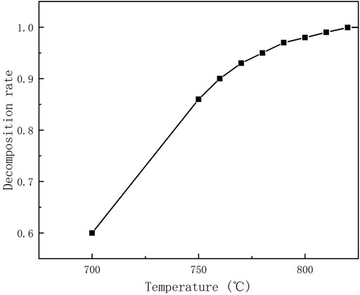
FIGURE 9. Experimental data of ammonia decomposition.
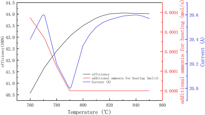
FIGURE 10. Output characteristics of the system based on experimental data of ammonia decomposition.
Conclusion
In this paper, a thermal simulation model of a PEMFC system directly fueled by ammonia decomposition gas is developed to study and analyze the maximum efficiency of the system and the key factors affecting the system efficiency. It enables a more scientific and quantitative assessment of the potential value of ADG-PEMFC. The following conclusions were obtained from the simulation analysis.
1) The ideal efficiency of the system based on the current commercial PEMFC (not optimized for mixed gas fuel) can reach 45.02% at the ammonia decomposition temperature of 418°C. Although increasing the ammonia decomposition reaction temperature will lead to a decrease in system efficiency, the decrease is small, so the system can obtain relatively good efficiency at higher ammonia decomposition reaction temperatures. The efficiency of the system obtained from the experimental data of ammonia decomposition in this paper is 44.05%, which shows that it has a high potential for development.
2) The main energy loss in the system is the heat loss of the fuel cell, but due to the defect of exhaust gas waste heat recovery, the improvement of the system efficiency by increasing the operating temperature of the fuel cell is small. Optimizing the PEMFC using ammonia decomposition gas and ensuring the reuse of anode tail gas are the two main ways to improve the system efficiency.
3) In order to ensure that the system can obtain high system efficiency, the actual system should meet the decomposition rate of ammonia to make the system have a critical current.
4) At the ammonia decomposition temperature of 650°C, the reuse of anode tail gas energy can increase the efficiency of the system from 40 to 44.05%.
Data Availability Statement
The raw data supporting the conclusion of this article will be made available by the authors, without undue reservation.
Author Contributions
JZ commonly finished the manuscript. YL conduct the experiment. All authors have read and approved the final manuscript.
Conflict of Interest
The authors declare that the research was conducted in the absence of any commercial or financial relationships that could be construed as a potential conflict of interest.
Publisher’s Note
All claims expressed in this article are solely those of the authors and do not necessarily represent those of their affiliated organizations, or those of the publisher, the editors and the reviewers. Any product that may be evaluated in this article, or claim that may be made by its manufacturer, is not guaranteed or endorsed by the publisher.
References
Aasadnia, M., Mehrpooya, M., and Ghorbani, B. (2021). A Novel Integrated Structure for Hydrogen Purification Using the Cryogenic Method. J. Clean. Prod. 278, 123872. doi:10.1016/j.jclepro.2020.123872
Alagharu, V., Palanki, S., and West, K. N. (2010). Analysis of Ammonia Decomposition Reactor to Generate Hydrogen for Fuel Cell Applications. J. Power Sourc. 195 (3), 829–833. doi:10.1016/j.jpowsour.2009.08.024
Araya, S. S., Zhou, F., Liso, V., Sahlin, S. L., Vang, J. R., Thomas, S., et al. (2016). A Comprehensive Review of PBI-Based High Temperature Pem Fuel Cells. Int. J. Hydrogen Energ. 41 (46), 21310–21344. doi:10.1016/j.ijhydene.2016.09.024
Aziz, M., Wijayanta, A. T., and Nandiyanto, A. B. D. (2020). Ammonia as Effective Hydrogen Storage: a Review on Production, Storage and Utilization. Energies 13 (12), 3062. doi:10.3390/en13123062
Badescu, V. (2020). Optimal Design and Operation of Ammonia Decomposition Reactors. Int. J. Energ. Res 44 (7), 5360–5384. doi:10.1002/er.5286
Barelli, L., Bidini, G., and Cinti, G. (2020). Operation of a Solid Oxide Fuel Cell Based Power System with Ammonia as a Fuel: Experimental Test and System Design. Energies 13 (23), 6173. doi:10.3390/en13236173
Cha, J., Jo, Y. S., Jeong, H., Han, J., Nam, S. W., Song, K. H., et al. (2018). Ammonia as an Efficient COX-free Hydrogen Carrier: Fundamentals and Feasibility Analyses for Fuel Cell Applications. Appl. Energ. 224, 194–204. doi:10.1016/j.apenergy.2018.04.100
Cinti, G., Liso, V., Sahlin, S. L., and Araya, S. S. (2020). System Design and Modeling of a High Temperature Pem Fuel Cell Operated with Ammonia as a Fuel. Energies 13 (18), 4689. doi:10.3390/en13184689
Dolan, M. D., Viano, D. M., Langley, M. J., and Lamb, K. E. (2018). Tubular Vanadium Membranes for Hydrogen Purification. J. Membr. Sci. 549, 306–311. doi:10.1016/j.memsci.2017.12.031
Fujitani, T., Nakamura, I., Hashiguchi, Y., Kanazawa, S., and Takahashi, A. (2020). Effect of Catalyst Preparation Method on Ammonia Decomposition Reaction over Ru/MgO Catalyst. Bcsj 93 (10), 1186–1192. doi:10.1246/bcsj.20200103
Galizia, M., Chi, W. S., Smith, Z. P., Merkel, T. C., Baker, R. W., and Freeman, B. D. (2017). 50th Anniversary Perspective: Polymers and Mixed Matrix Membranes for Gas and Vapor Separation: a Review and Prospective Opportunities. Macromolecules 50 (20), 7809–7843. doi:10.1021/acs.macromol.7b01718
Garagounis, L., Vourros, A., Stoukides, D., and Dasopoulos, M. (2019). Electrochemical Synthesis of Ammonia: Recent Efforts and Future Outlook. Membranes 9 (9), 112. doi:10.3390/membranes9090112
Hashinokuchi, M., Zhang, M., Doi, T., and Inaba, M. (2018). Enhancement of Anode Activity and Stability by Cr Addition at Ni/Sm-Doped CeO2 Cermet Anodes in NH3-fueled Solid Oxide Fuel Cells. Solid State Ionics 319, 180–185. doi:10.1016/j.ssi.2018.02.015
Hunter, H. M. A., Makepeace, J. W., Wood, T. J., Mylius, O. S., Kibble, M. G., Nutter, J. B., et al. (2016). Demonstrating Hydrogen Production from Ammonia Using Lithium Imide - Powering a Small Proton Exchange Membrane Fuel Cell. J. Power Sourc. 329, 138–147. doi:10.1016/j.jpowsour.2016.08.004
Imamura, D., Matsuda, Y., Hashimasa, Y., and Akai, M. (2011). Effect of Ammonia Contained in Hydrogen Fuel on PEMFC Performance. ECS Trans. 41 (1), 2083–2089. doi:10.1149/1.3635738
Iulianelli, A., Ghasemzadeh, K., Marelli, M., and Evangelisti, C. (2019). A Supported Pd-Cu/Al2O3 Membrane from Solvated Metal Atoms for Hydrogen Separation/purification. Fuel Process. Tech. 195, 106141. doi:10.1016/j.fuproc.2019.106141
Iverson, E. B., Baxter, D. V., Gallmeier, F. X., Gillis, R. C., Hügle, T., Lu, W., et al. (2018). Characterization of a Liquid Ammonia Moderator. J. Phys. Conf. Ser. 1021, 012067. doi:10.1088/1742–6596/1021/1/012067
Kim, J. H., and Kwon, O. C. (2011). A Micro Reforming System Integrated with a Heat-Recirculating Micro-combustor to Produce Hydrogen from Ammonia. Int. J. Hydrogen Energ. 36 (3), 1974–1983. doi:10.1016/j.ijhydene.2010.11.043
Kim, K., Roh, G., Kim, W., and Chun, K. (2020). A Preliminary Study on an Alternative Ship Propulsion System Fueled by Ammonia: Environmental and Economic Assessments. Jmse 8 (3), 183. doi:10.3390/jmse8030183
Li, B., He, G., Jiang, X., Dai, Y., and Ruan, X. (2016). Pressure Swing Adsorption/membrane Hybrid Processes for Hydrogen Purification with a High Recovery. Front. Chem. Sci. Eng. 10 (2), 255–264. doi:10.1007/s11705-016-1567-1
Li, J., Huang, H., Kobayashi, N., He, Z., and Nagai, Y. (2014). Study on Using Hydrogen and Ammonia as Fuels: Combustion Characteristics and NOxformation. Int. J. Energ. Res. 38 (9), 1214–1223. doi:10.1002/er.3141
Lin, L., Tian, Y., Su, W., Luo, Y., Chen, C., and Jiang, L. (2020). Techno-economic Analysis and Comprehensive Optimization of Anon-Sitehydrogen Refuelling Station System Using Ammonia: Hybrid Hydrogen Purification with Both High H2purity and High Recovery. Sust. Energ. Fuels 4 (6), 3006–3017. doi:10.1039/c9se01111k
Lopes, T., Sansiñena, J.-M., Mukundan, R., Hussey, D. S., Jacobson, D. L., and Garzon, F. H. (2014). Diagnosing the Effects of Ammonia Exposure on Pefc Cathodes. J. Electrochem. Soc. 161 (6), F703–F709. doi:10.1149/2.028406jes
Lu, W., Xia, M., Hong, W., Huang, K., and Ozin, G. A. (2018). Greening Ammonia toward the Solar Ammonia Refinery. Joule 2 (6), 1055–1074. doi:10.1016/j.joule.2018.04.017
McDonald, C. F. (2000). Low-cost Compact Primary Surface Recuperator Concept for Microturbines. Appl. Therm. Eng. 20 (5), 471–497. doi:10.1016/s1359-4311(99)00033-2
Mckinlay, C. J., Turnock, S. R., and Hudson, D. A. (2021). ARoute to Zero Emission Shipping: Hydrogen, Ammonia or Methanol? Int. J. Hydrogen Energ. 46, 28282–28297. doi:10.1016/j.ijhydene.2021.06.066
Miyaoka, H., Miyaoka, H., Ichikawa, T., Ichikawa, T., and Kojima, Y. (2018). Highly Purified Hydrogen Production from Ammonia for PEM Fuel Cell. Int. J. Hydrogen Energ. 43 (31), 14486–14492. doi:10.1016/j.ijhydene.2018.06.065
Naha, B., Vm, A., and Asaa, B. (2019). Ammonia- Hydrogen Combustion in a Swirl Burner with Reduction of NOx Emissions - Sciencedirect. Energ. Proced. 158, 2305–2310. doi:10.1016/j.egypro.2019.01.265
Ni, M., Leung, M. K. H., and Leung, Y. (2010). Ammonia-fed Solid Oxide Fuel Cells for Power Generation—A Review. Int. J. Energ. Res. 33 (11), 943–959. doi:10.1002/er.1588
Okanishi, T., Okura, K., Srifa, A., Muroyama, H., Matsui, T., Kishimoto, M., et al. (2017). Comparative Study of Ammonia‐fueled Solid Oxide Fuel Cell Systems. Fuel Cells 17 (3), 383–390. doi:10.1002/fuce.201600165
Perna, A., Minutillo, M., Micco, S. D., Cigolotti, V., and Pianese, A. (2020). Ammonia as Hydrogen Carrier for Realizing Distributed On-Site Refueling Stations Implementing Pemfc Technology. E3S Web of Conferences, 197 05001. doi:10.1051/e3sconf/202019705001
Sayas, S., Morlanés, N., Katikaneni, S. P., Harale, A., Solami, B., and Gascon, J. (2020). High Pressure Ammonia Decomposition on Ru-K/CaO Catalysts. Catal. Sci. Technol. 10 (15), 5027–5035. doi:10.1039/d0cy00686f
Wang, L., Wan, X., Liu, S., Xu, L., and Shui, J. (2019). Fe-N-C Catalysts for PEMFC: Progress towards the Commercial Application under DOE Reference. J. Energ. Chem. 39 (12), 77–87. doi:10.1016/j.jechem.2018.12.019
Wu, S., Che, D., Wang, Z., and Su, X. (2020). NOx Emissions and Nitrogen Fate at High Temperatures in Staged Combustion. Energies 13 (14), 1–17. doi:10.3390/en13143557
Yapicioglu, A., and Dincer, I. (2019). A Review on Clean Ammonia as a Potential Fuel for Power Generators. Renew. Sust. Energ. Rev. 103 (APR.), 96–108. doi:10.1016/j.rser.2018.12.023
Zeng, Z., Qian, Y., Zhang, Y., Hao, C., Dan, D., and Zhuge, W. (2020). A Review of Heat Transfer and thermal Management Methods for Temperature Gradient Reduction in Solid Oxide Fuel Cell (Sofc) Stacks. Appl. Energ. 280, 115899. doi:10.1016/j.apenergy.2020.115899
Keywords: ammonia, ammonia decomposition gas, PEMFC, efficiency, simulation
Citation: Zhao JF, Liang QC and Liang YF (2022) Simulation and Study of PEMFC System Directly Fueled by Ammonia Decomposition Gas. Front. Energy Res. 10:819939. doi: 10.3389/fenrg.2022.819939
Received: 22 November 2021; Accepted: 14 February 2022;
Published: 22 March 2022.
Edited by:
Jinliang Yuan, Ningbo University, ChinaReviewed by:
Shanwen Tao, University of Warwick, United KingdomYusuf Bicer, Hamad bin Khalifa University, Qatar
Copyright © 2022 Zhao, Liang and Liang. This is an open-access article distributed under the terms of the Creative Commons Attribution License (CC BY). The use, distribution or reproduction in other forums is permitted, provided the original author(s) and the copyright owner(s) are credited and that the original publication in this journal is cited, in accordance with accepted academic practice. No use, distribution or reproduction is permitted which does not comply with these terms.
*Correspondence: Jian Feng Zhao, amlhbmZlbmc2MjMwMF96aGFvQDE2My5jb20=